2005 SUZUKI JIMNY king
[x] Cancel search: kingPage 166 of 687

Downloaded from www.Manualslib.com manuals search engine STEERING WHEEL AND COLUMN 3C-13
8) If equipped with shift (key) interlock cable (1), remove shift
(key) interlock cable screw (2) and then disconnect its cable
from ignition switch in order a) – c) as shown in the figure.
9) Remove steering column from vehicle.
10) Remove steering column seal (1) from steering column lower
bracket.
INSPECTION
CHECKING PROCEDURE
1) Check that two capsules (1) are attached to steering column
bracket (2) securely. Check clearance between capsules and
steering column bracket. Clearance should be 0.0 mm (0.0
in.) on both sides.
If found loose or clearance, replace steering column assem-
bly.
2) Check two plates (3) for any damages such as crack or
breakage.
If anything is found faulty, replace as steering column
assembly.
CAUTION:
Don’t separate double tube type steering column assem-
bly into steering column and shaft. If column or shaft is
defective, replace as and assembly.
NOTE:
Vehicles involved in accidents resulting in body damage,
where steering column has been impacted (or air bag
deployed), may have a damaged or misaligned steering
column.
Page 171 of 687

Downloaded from www.Manualslib.com manuals search engine 3C-18 STEERING WHEEL AND COLUMN
Checking Steering Column for Accident Damage
CHECKING PROCEDURE
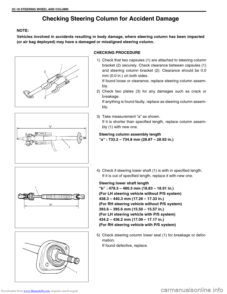
1) Check that two capsules (1) are attached to steering column
bracket (2) securely. Check clearance between capsules (1)
and steering column bracket (2). Clearance should be 0.0
mm (0.0 in.) on both sides.
If found loose or clearance, replace steering column assem-
bly.
2) Check two plates (3) for any damages such as crack or
breakage.
If anything is found faulty, replace as steering column assem-
bly.
3) Take measurement “a” as shown.
If it is shorter than specified length, replace column assem-
bly (1) with new one.
Steering column assembly length
“a” : 733.2 – 734.8 mm (28.87 – 28.93 in.)
4) Check if steering lower shaft (1) is with in specified length.
If it is out of specified length, replace it with new one.
Steering lower shaft length
“b” : 478.3 – 480.3 mm (18.83 – 18.91 in.)
(For LH steering vehicle without P/S system)
438.3 – 440.3 mm (17.26 – 17.33 in.)
(For RH steering vehicle without P/S system)
393.6 – 395.6 mm (15.50 – 15.57 in.)
(For LH steering vehicle with P/S system)
434.2 – 436.2 mm (17.09 – 17.17 in.)
(For RH steering vehicle with P/S system)
5) Check steering column lower seal (1) for breakage or defor-
mation.
If found defective, replace. NOTE:
Vehicles involved in accidents resulting in body damage, where steering column has been impacted
(or air bag deployed) may have a damaged or misaligned steering column.
Page 174 of 687

Downloaded from www.Manualslib.com manuals search engine FRONT SUSPENSION 3D-1
6F1
6F2
6G
1A
6K
7A
7A1
3D
7F
8A
8A
8B
8C
8D
8E
9
10
10A
10B
SECTION 3D
FRONT SUSPENSION
CONTENTS
General Description ....................................... 3D-2
4WD Control System .................................... 3D-2
Diagnosis ........................................................ 3D-8
Diagnosis Table ........................................... 3D-8
4WD Controller and ITS Circuit Check ....... 3D-10
4WD Control System Check ...................... 3D-11
Stabilizer bar / bushing check ................ 3D-13
Shock Absorber and/or Coil Spring
Check ......................................................... 3D-14
Leading Arm / Lateral Rod / Steering
Knuckle Check ........................................... 3D-14
Leading Arm Bushing / Lateral Rod
Bushing Check ........................................... 3D-15
Kingpin / Kingpin Bearing Check ................ 3D-15
Barfield Joint Check ................................... 3D-15
Steering Knuckle Seal Check ..................... 3D-15
Wheel Disc, Nut and Bearing Check .......... 3D-16On-Vehicle Service ...................................... 3D-17
Stabilizer Bar / Bushings ............................ 3D-17
Front Shock Absorber ................................ 3D-19
Coil Spring ................................................. 3D-19
Bump Stopper and Spring Upper Seat ...... 3D-21
Wheel Hub / Bearing / Oil Seal .................. 3D-21
Steering Knuckle / Wheel Spindle.............. 3D-28
Front Axle Shaft / Oil Seal / Kingpin
Bearing Outer Race ................................... 3D-32
Steering Knuckle Seal................................ 3D-34
Lateral Rod ................................................ 3D-35
Leading Arm / Bushing............................... 3D-36
Front Axle Housing .................................... 3D-38
Tightening Torque Specifications .............. 3D-44
Required Service Material ........................... 3D-44
Special Tool .................................................. 3D-45
WARNING:
When hoisting vehicle, be sure to select the lifting point suitable for the service work referring to Sec-
tion 0A.
NOTE:
All front suspension fasteners are an important attaching part in that it could affect the performance
of vital parts and systems, and/or could result in major repair expense. They must be replaced with
one of the same part number or with an equivalent part if replacement becomes necessary. Do not
use a replacement part of lesser quality or substitute design. Torque values must be used as speci-
fied during reassembly to assure proper retention of this part.
Never attempt to heat, quench or straighten any front suspension part. Replace it with a new part or
damage to the part may result.
Page 175 of 687

Downloaded from www.Manualslib.com manuals search engine 3D-2 FRONT SUSPENSION
General Description
4WD Control System
The 4WD control system consists of a 4WD switch, a vacuum switch, a vacuum tank, two vacuum switching
valves (VSV1 and VSV2) and air locking hub assemblies.
The 4WD controller controls locking or unlocking of the air locking hub according to operation of the transfer shift
control lever.
Vacuum generated in the intake manifold passes through the check valve and stored in the vacuum tank.
According to signals from the 4WD switch, the 4WD controller activates VSV1 (for unlocking) or VSV2 (for lock-
ing) to apply vacuum from the vacuum tank so that the front axle and the wheel hub are disengaged or engaged.
1. Front axle housing 3. Steering knuckle 5. Wheel spindle 7. Wheel bearing
2. Shock absorber 4. Kingpin 6. Wheel hub 8. Front axle shaft (4WD)
Page 176 of 687

Downloaded from www.Manualslib.com manuals search engine FRONT SUSPENSION 3D-3
1. Air locking hub assembly 4. VSV2 7. 4WD controller 10. 4WD indicator light 13. ABS controller
2. VSV1 5. Vacuum accumulation tank 8. Intake manifold 11. 4WD switch 14. Transfer
3. Check valve 6. Vacuum switch 9. Wheel spindle 12. Combination meter
Page 178 of 687

Downloaded from www.Manualslib.com manuals search engine FRONT SUSPENSION 3D-5
Components and Functions
Component Function
4WD switch When the transfer shift lever is shifted to 4L or 4H position from 2H, this switch
turns ON and cause the 4WD control system to turn ON.
4WD controller When the 4WD switch turns on, the 4WD controller activates VSV2 to lock the
air locking hubs and when it receives an “ON” signal from the vacuum switch, it
makes VSV2 to complete operation within 5 seconds and causes the 4WD indi-
cator light to light up.
If vacuum in the vacuum circuit fails to reach the specified level due to a leakage
in the vacuum circuit (when no “ON” signal is inputted from the vacuum switch),
the 4WD controller stops operation of VSV2 in 15 seconds and makes the 4WD
indicator light to flash to warn occurrence of a trouble.
When the 4WD switch turns off, the 4WD controller activates VSV1 for 10 sec-
onds to unlock the hubs and at the same time makes the 4WD indicator light
turn off.
VSV1 VSV1 operates according to the signal from the 4WD controller. When it is acti-
vated, the port opens and vacuum in the intake manifold is applied through the
vacuum circuit to unlock to the slide gear in the air locking hub. As a result, the
air locking hubs are unlocked.
VSV2 VSV2 operates according to the signal from the 4WD controller. When it is acti-
vated, the port opens and vacuum in the intake manifold is applied through the
vacuum circuit to lock to the slide gear in the air locking hub. As a result, the air
locking hubs are locked.
Vacuum switch When VSV2 receives the “ON” signal from 4WD switch, vacuum is applied
through its circuit to the vacuum switch. The vacuum switch turns on when it
detects vacuum exceeding 260 mmHg.
“4WD” indicator lamp It lights up when 4WD control system is in the 4WD mode.
It flashes to warn that locking hub operation has not completed (4WD control
system fails to shift 4WD).
Page 181 of 687

Downloaded from www.Manualslib.com manuals search engine 3D-8 FRONT SUSPENSION
Diagnosis
Diagnosis Table
For description not found in the table below, refer to “Diagnosis Table” in Section 3.
4WD CONTROL SYSTEM
4WD CONTROL SYSTEM DIAGNOSTIC FLOW TABLE
Before performing the trouble diagnosis, check that the air locking hub assemblies are in good condition and
there is no air leakage from vacuum hoses and vacuum pipe. Refer to “4WD Control System Check” in this sec-
tion for air leakage.
[NOTES ON SYSTEM CIRCUIT INSPECTION]
Be sure to read “Precautions for Electrical Circuit Service” in Section 0A before circuit inspection and
observe what is written there.
For system circuit, refer to the figure of “System Circuit” in this section. Condition Possible Cause Correction
4WD Indicator light
flashingHub locking procedure error
Defective VSV2
Defective vacuum switch
Defective check valve or vacuum tank
Air leak from vacuum circuit
Clogged vacuum hose or pipe
Faulty 4WD controllerShift transfer shift control lever
2WD → 4WD once again
Replace
Replace
Replace
Check and repair
Replace
Check and replace
2WD/4WD switching
errorDefective air locking hub assembly
Abnormality in 4WD control system
Air leakage from vacuum circuit
Clogged vacuum hose or pipe
Defective check valve or vacuum tankReplace
Inspect referring to “4WD Control
System Diagnostic Flow Table”
Check and replace
Replace
Replace
Step Action Yes No
1 Check ground circuit.
1) Disconnect coupler from 4WD controller
with ignition switch OFF.
2) Check for proper connection to 4WD con-
troller at all terminals.
3) If OK, check continuity between A5 terminal
and body ground.
Is there continuity between A5 terminal and
body ground?Go to Step 2.“B” wire is open.
2 Check power circuit.
1) Disconnect coupler from 4WD controller.
2) Turn ignition switch ON.
3) Check voltage between A10 terminal and
ground.
Is it 10 – 14 V?Go to Step 3.“Y/R” circuit is open or
short.
Page 184 of 687

Downloaded from www.Manualslib.com manuals search engine FRONT SUSPENSION 3D-11
4WD Control System Check
AIR LOCKING HUB
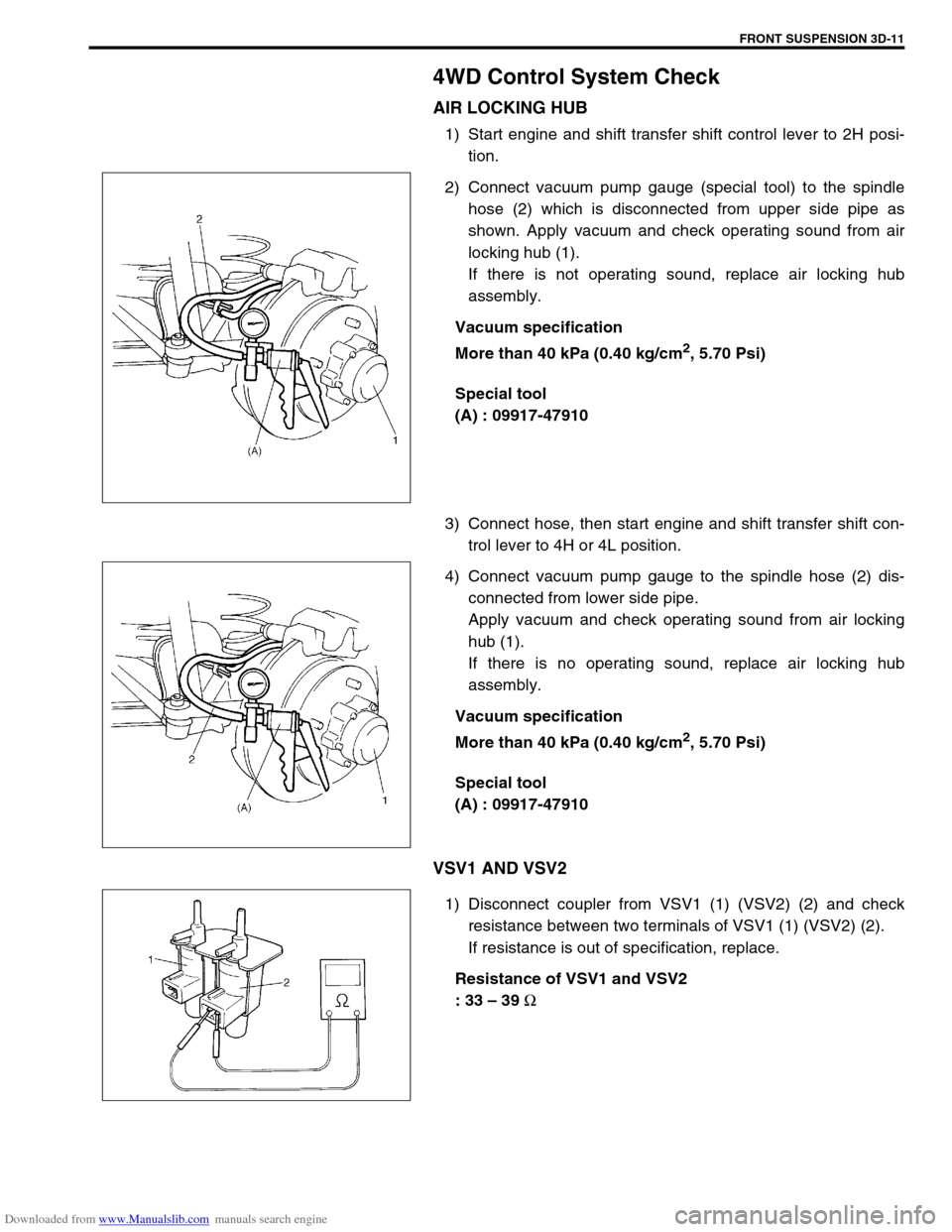
1) Start engine and shift transfer shift control lever to 2H posi-
tion.
2) Connect vacuum pump gauge (special tool) to the spindle
hose (2) which is disconnected from upper side pipe as
shown. Apply vacuum and check operating sound from air
locking hub (1).
If there is not operating sound, replace air locking hub
assembly.
Vacuum specification
More than 40 kPa (0.40 kg/cm
2, 5.70 Psi)
Special tool
(A) : 09917-47910
3) Connect hose, then start engine and shift transfer shift con-
trol lever to 4H or 4L position.
4) Connect vacuum pump gauge to the spindle hose (2) dis-
connected from lower side pipe.
Apply vacuum and check operating sound from air locking
hub (1).
If there is no operating sound, replace air locking hub
assembly.
Vacuum specification
More than 40 kPa (0.40 kg/cm
2, 5.70 Psi)
Special tool
(A) : 09917-47910
VSV1 AND VSV2
1) Disconnect coupler from VSV1 (1) (VSV2) (2) and check
resistance between two terminals of VSV1 (1) (VSV2) (2).
If resistance is out of specification, replace.
Resistance of VSV1 and VSV2
: 33 – 39
Ω