2005 SUZUKI JIMNY low oil pressure
[x] Cancel search: low oil pressurePage 580 of 687

Downloaded from www.Manualslib.com manuals search engine ENGINE COOLING 6B-3
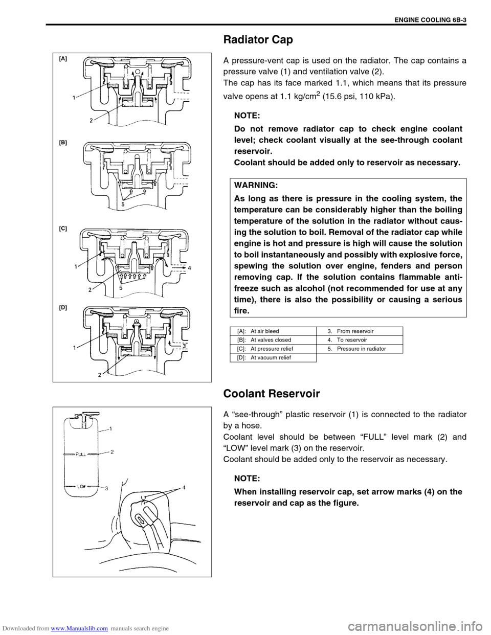
Radiator Cap
A pressure-vent cap is used on the radiator. The cap contains a
pressure valve (1) and ventilation valve (2).
The cap has its face marked 1.1, which means that its pressure
valve opens at 1.1 kg/cm
2 (15.6 psi, 110 kPa).
Coolant Reservoir
A “see-through” plastic reservoir (1) is connected to the radiator
by a hose.
Coolant level should be between “FULL” level mark (2) and
“LOW” level mark (3) on the reservoir.
Coolant should be added only to the reservoir as necessary.NOTE:
Do not remove radiator cap to check engine coolant
level; check coolant visually at the see-through coolant
reservoir.
Coolant should be added only to reservoir as necessary.
WARNING:
As long as there is pressure in the cooling system, the
temperature can be considerably higher than the boiling
temperature of the solution in the radiator without caus-
ing the solution to boil. Removal of the radiator cap while
engine is hot and pressure is high will cause the solution
to boil instantaneously and possibly with explosive force,
spewing the solution over engine, fenders and person
removing cap. If the solution contains flammable anti-
freeze such as alcohol (not recommended for use at any
time), there is also the possibility or causing a serious
fire.
[A]: At air bleed 3. From reservoir
[B]: At valves closed 4. To reservoir
[C]: At pressure relief 5. Pressure in radiator
[D]: At vacuum relief
NOTE:
When installing reservoir cap, set arrow marks (4) on the
reservoir and cap as the figure.
Page 584 of 687

Downloaded from www.Manualslib.com manuals search engine ENGINE COOLING 6B-7
Coolant Level
To check level, look at “see-through” reservoir.
It is not necessary to remove radiator cap to check coolant level.
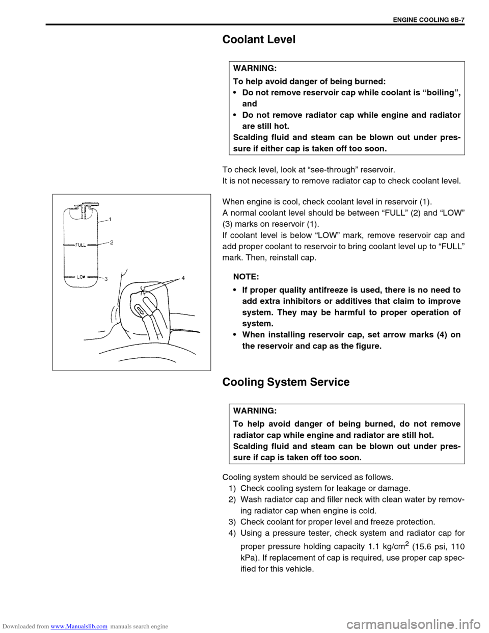
When engine is cool, check coolant level in reservoir (1).
A normal coolant level should be between “FULL” (2) and “LOW”
(3) marks on reservoir (1).
If coolant level is below “LOW” mark, remove reservoir cap and
add proper coolant to reservoir to bring coolant level up to “FULL”
mark. Then, reinstall cap.
Cooling System Service
Cooling system should be serviced as follows.
1) Check cooling system for leakage or damage.
2) Wash radiator cap and filler neck with clean water by remov-
ing radiator cap when engine is cold.
3) Check coolant for proper level and freeze protection.
4) Using a pressure tester, check system and radiator cap for
proper pressure holding capacity 1.1 kg/cm
2 (15.6 psi, 110
kPa). If replacement of cap is required, use proper cap spec-
ified for this vehicle. WARNING:
To help avoid danger of being burned:
Do not remove reservoir cap while coolant is “boiling”,
and
Do not remove radiator cap while engine and radiator
are still hot.
Scalding fluid and steam can be blown out under pres-
sure if either cap is taken off too soon.
NOTE:
If proper quality antifreeze is used, there is no need to
add extra inhibitors or additives that claim to improve
system. They may be harmful to proper operation of
system.
When installing reservoir cap, set arrow marks (4) on
the reservoir and cap as the figure.
WARNING:
To help avoid danger of being burned, do not remove
radiator cap while engine and radiator are still hot.
Scalding fluid and steam can be blown out under pres-
sure if cap is taken off too soon.
Page 613 of 687

Downloaded from www.Manualslib.com manuals search engine 6E-8 ENGINE AND EMISSION CONTROL SYSTEM
Engine & emission control input / output table
INPUTOUTPUT
ELECTRIC CONTROL DEVICE
DIAGNOSIS SWITCH TERMINAL
(VEHICLE WITHOUT IMMOBILIZER INDICATOR LAMP)
BAROMETRIC PRESSURE SENSOR
(VEHICLE WITH IMMOBILIZER INDICATOR LAMP)
STOP LAMP SWITCH
STARTER SWITCH
IGNITION SWITCH
LIGHTING SWITCH
REAR DEFOGGER SWITCH (IF EQUIPPED)
BLOWER SWITCH
A/C SWITCH (IF EQUIPPED)
A/C EVAPORATOR TEMP. SENSOR (IF EQUIPPED)
VSS
HEATED OXYGEN SENSOR-1 (IF EQUIPPED)
HEATED OXYGEN SENSOR-2
(IF EQUIPPED)For detecting deterioration of
three way catalytic converter
IAT SENSOR
ECT SENSOR
TP SENSOR
MAP SENSOR
CMP SENSOR
CKP SENSOR
TEST SWITCH TERMINAL
(VEHICLE WITHOUT IMMOBILIZER INDICATOR LAMP)
KNOCK SENSOR
FUEL PUMP RELAY
FUEL INJECTOR
HO2S HEATER
IAC VALVE
IGNITION COIL WITH IGNITER
EGR VALVE (IF EQUIPPED)
EVAP CANISTER PURGE VALVE
A/C COMPRESSOR CLUTCH
MIL
MAIN RELAY
TRANSMISSION CONTROL MODULE SIGNAL FROM SENSOR, SWITCH AND CONTROL MODULEA/C CONDENSER FAN RELAY
Page 618 of 687

Downloaded from www.Manualslib.com manuals search engine ENGINE AND EMISSION CONTROL SYSTEM 6E-13
ECM TERMINAL ARRANGEMENT TABLE
For TYPE A (See NOTE)
CONNEC-
TORTERMINAL WIRE COLOR CIRCUITCONNEC-
TORTERMINAL WIRE COLOR CIRCUIT
E191 B Ground for ECM
E187 W Backup power source
2 B/R Ground for drive circuit
8R/GImmobilizer indicator lamp
(if equipped)
3 B/R Ground for drive circuitDuty output terminal (vehicle without
immobilizer indicator lamp)
4 Bl/G Canister purge valve 9––
5 Bl/OrPower steering pressure switch
(if equipped)10 Bl Main relay
6 G/Y IAC valve 11 Br Tachometer
7 P/B Heater of HO2S-1 (if equipped) 12 Y/B Data link connector (5 V)
8 W/B No.4 fuel injector 13 WHeated oxygen sensor-2
(if equipped)
9 R/W No.1 fuel injector 14 W/BIDiagnosis switch terminal
(vehicle without immobilizer indicator
lamp)
10 B/Bl Ground for sensor circuit 15 PTest switch terminal
(vehicle without immobilizer indicator
lamp)
11 W CMP sensor 16 G/W A/C SW signal (if equipped)
12––17 R/Y Lighting switch
13R
R/BlHeated oxygen sensor-1
(if equipped)
CO adjusting resistor (w/o HO2S)18 P/B A/C condenser fan relay (if equipped)
14 G/B ECT sensor 19 W/G Fuel pump relay
15 Lg/B IAT sensor 20 B/Bl Ground for sensor
16 Lg TP sensor 21 B/RThrottle opening signal output for A/T
(A/T)
17 Gr/BIEGR valve (stepper motor coil 3, if
equipped)22 Y/RFuel level gauge (vehicle with immo-
bilizer indicator lamp)
18 GrEGR valve (stepper motor coil 1, if
equipped)23––
19 Br/BIG coil assembly for No.2 and 3 spark
plugs24 Bl/Y Heater blower switch
20 Br/WIG coil assembly for No.1 and 4 spark
plugs
21 R/G No.2 fuel injector
E171––
22 Lg/R Power supply for sensor 2 R R-range signal (A/T)
23 G/R CKP sensor 3––
24––4––
25 W Knock sensor 5 B/Or Overdrive cut signal (A/T)
26 G MAP sensor 6 G/Y D-range idle-up signal (A/T)
27 W/R A/C evaporator temp. sensor 7 G/W Stop lamp switch
28 Gr/BEGR valve (stepper motor coil 4, if
equipped)8––
29 Gr/REGR valve (stepper motor coil 2, if
equipped)9 B/W Ignition switch
30––10––
31 W/G No.3 fuel injector 11 Y Vehicle speed sensor
12 G ABS signal (if equipped)
E181 P A/C compressor clutch (if equipped) 13B/Y (M/T)
B/R (A/T)Engine start signal
2 V/Y Malfunction indicator lamp 14––
3 P/G Data link connector (12 V) 15––
4 R/BI Heater of HO2S-2 (if equipped) 16 R/W Rear defogger switch (if equipped)
5 Bl/B Power source 17 G/RA/T failure signal (A/T) (vehicle with
immobilizer indicator lamp)
6 Bl/B Power source
NOTE:
See NOTE in “ECM INPUT / OUTPUT CIRCUIT DIAGRAM” for applicable model.
Page 619 of 687

Downloaded from www.Manualslib.com manuals search engine 6E-14 ENGINE AND EMISSION CONTROL SYSTEM
For TYPE B (See NOTE)
CONNEC-
TORTERMINAL WIRE COLOR CIRCUITCONNEC-
TORTERMINAL WIRE COLOR CIRCUIT
E191 B Ground for ECM
E187 W Backup power source
2 B/R Ground for drive circuit
8R/GImmobilizer indicator lamp
(if equipped)
3 B/R Ground for drive circuitDuty output terminal (vehicle without
immobilizer indicator lamp)
4 Bl/G Canister purge valve 9––
5 Bl/OrPower steering pressure switch
(if equipped)10 Bl Main relay
6 G/Y IAC valve 11 B/W Ignition switch
7 P/B Heater of HO2S-1 (if equipped) 12 R/W Rear defogger switch
8 W/B No.4 fuel injector 13––
9 R/W No.1 fuel injector 14 W/BIDiagnosis switch terminal
(vehicle without immobilizer indicator
lamp)
10 B/Bl Ground for sensor circuit 15 PTest switch terminal
(vehicle without immobilizer indicator
lamp)
11 W CMP sensor 16 G/W A/C SW signal (if equipped)
12––17 R/Y Lighting switch
13R
R/BlHeated oxygen sensor-1
(if equipped)
CO adjusting resistor (w/o HO2S)18 P/B A/C condenser fan relay (if equipped)
14 G/B ECT sensor 19 W/G Fuel pump relay
15 Lg/B IAT sensor 20B/Y (M/T)
B/R (A/T)Engine start signal
16 Lg TP sensor 21 G/W Stop lamp switch
17 Gr/BIEGR valve (stepper motor coil 3, if
equipped)22 Y Vehicle speed sensor
18 GrEGR valve (stepper motor coil 1, if
equipped)23––
19 Br/BIG coil assembly for No.2 and 3 spark
plugs24––
20 Br/WIG coil assembly for No.1 and 4 spark
plugs
21 R/G No.2 fuel injector
E171 W/R A/C evaporator temp. sensor
22 Lg/R Power supply for sensor 2 R R-range signal (A/T)
23 G/R CKP sensor 3––
24––4––
25 W Knock sensor 5 B/Or Overdrive cut signal (A/T)
26 G MAP sensor 6 G/Y D-range idle-up signal (A/T)
27––7 Y/B Data link connector
28 Gr/BEGR valve (stepper motor coil 4, if
equipped)8––
29 Gr/REGR valve (stepper motor coil 2, if
equipped)9 V/Y Malfunction indicator lamp
30––10––
31 W/G No.3 fuel injector 11 P/G Data link connector (12 V)
12 G ABS signal (if equipped)
E181 P A/C compressor clutch (if equipped) 13 Bl/Y Heater blower switch
2––14 B/Bl Ground for sensor
3––15 B/R Throttle opening sensor
4 R/BI Heater of HO2S-2 (if equipped) 16 Br Tachometer
5 Bl/B Power source 17––
6 Bl/B Power source
NOTE:
See NOTE in “ECM INPUT / OUTPUT CIRCUIT DIAGRAM” for applicable model.