Page 552 of 687
Downloaded from www.Manualslib.com manuals search engine ENGINE MECHANICAL (M13 ENGINE) 6A1-71
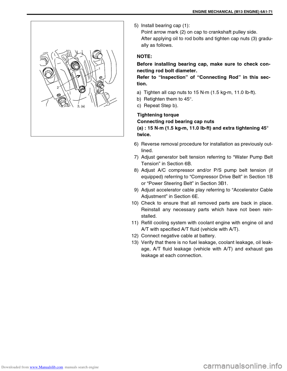
5) Install bearing cap (1):
Point arrow mark (2) on cap to crankshaft pulley side.
After applying oil to rod bolts and tighten cap nuts (3) gradu-
ally as follows.
a) Tighten all cap nuts to 15 N·m (1.5 kg-m, 11.0 lb-ft).
b) Retighten them to 45°.
c) Repeat Step b).
Tightening torque
Connecting rod bearing cap nuts
(a) : 15 N·m (1.5 kg-m, 11.0 lb-ft) and extra tightening 45°
twice.
6) Reverse removal procedure for installation as previously out-
lined.
7) Adjust generator belt tension referring to “Water Pump Belt
Tension” in Section 6B.
8) Adjust A/C compressor and/or P/S pump belt tension (if
equipped) referring to “Compressor Drive Belt” in Section 1B
or “Power Steering Belt” in Section 3B1.
9) Adjust accelerator cable play referring to “Accelerator Cable
Adjustment” in Section 6E.
10) Check to ensure that all removed parts are back in place.
Reinstall any necessary parts which have not been rein-
stalled.
11) Refill cooling system with coolant engine with engine oil and
A/T with specified A/T fluid (vehicle with A/T).
12) Connect negative cable at battery.
13) Verify that there is no fuel leakage, coolant leakage, oil leak-
age, A/T fluid leakage (vehicle with A/T) and exhaust gas
leakage at each connection. NOTE:
Before installing bearing cap, make sure to check con-
necting rod bolt diameter.
Refer to “Inspection” of “Connecting Rod” in this sec-
tion.
Page 559 of 687
Downloaded from www.Manualslib.com manuals search engine 6A1-78 ENGINE MECHANICAL (M13 ENGINE)
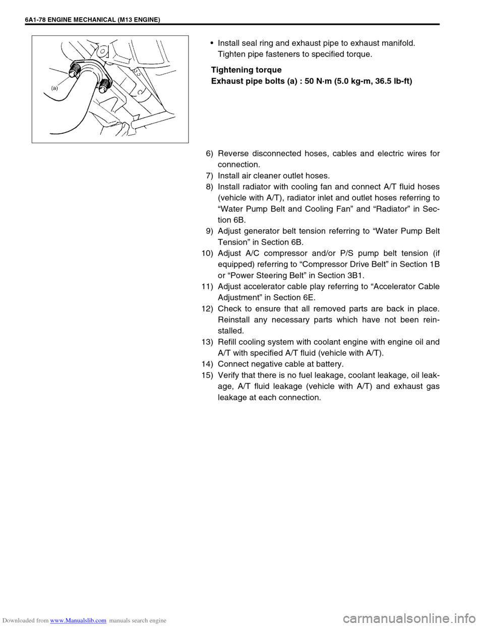
Install seal ring and exhaust pipe to exhaust manifold.
Tighten pipe fasteners to specified torque.
Tightening torque
Exhaust pipe bolts (a) : 50 N·m (5.0 kg-m, 36.5 lb-ft)
6) Reverse disconnected hoses, cables and electric wires for
connection.
7) Install air cleaner outlet hoses.
8) Install radiator with cooling fan and connect A/T fluid hoses
(vehicle with A/T), radiator inlet and outlet hoses referring to
“Water Pump Belt and Cooling Fan” and “Radiator” in Sec-
tion 6B.
9) Adjust generator belt tension referring to “Water Pump Belt
Tension” in Section 6B.
10) Adjust A/C compressor and/or P/S pump belt tension (if
equipped) referring to “Compressor Drive Belt” in Section 1B
or “Power Steering Belt” in Section 3B1.
11) Adjust accelerator cable play referring to “Accelerator Cable
Adjustment” in Section 6E.
12) Check to ensure that all removed parts are back in place.
Reinstall any necessary parts which have not been rein-
stalled.
13) Refill cooling system with coolant engine with engine oil and
A/T with specified A/T fluid (vehicle with A/T).
14) Connect negative cable at battery.
15) Verify that there is no fuel leakage, coolant leakage, oil leak-
age, A/T fluid leakage (vehicle with A/T) and exhaust gas
leakage at each connection.
Page 590 of 687
Downloaded from www.Manualslib.com manuals search engine ENGINE COOLING 6B-13
Water Pump Belt and Cooling Fan
REMOVAL
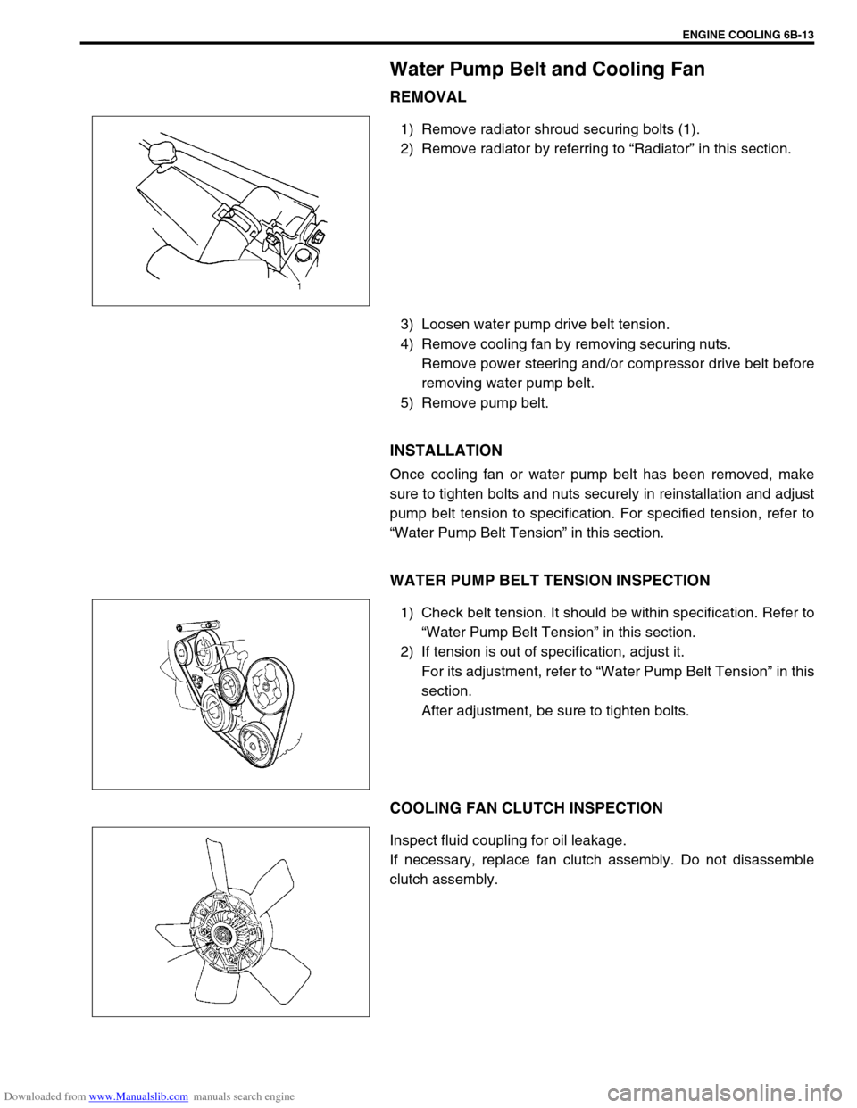
1) Remove radiator shroud securing bolts (1).
2) Remove radiator by referring to “Radiator” in this section.
3) Loosen water pump drive belt tension.
4) Remove cooling fan by removing securing nuts.
Remove power steering and/or compressor drive belt before
removing water pump belt.
5) Remove pump belt.
INSTALLATION
Once cooling fan or water pump belt has been removed, make
sure to tighten bolts and nuts securely in reinstallation and adjust
pump belt tension to specification. For specified tension, refer to
“Water Pump Belt Tension” in this section.
WATER PUMP BELT TENSION INSPECTION
1) Check belt tension. It should be within specification. Refer to
“Water Pump Belt Tension” in this section.
2) If tension is out of specification, adjust it.
For its adjustment, refer to “Water Pump Belt Tension” in this
section.
After adjustment, be sure to tighten bolts.
COOLING FAN CLUTCH INSPECTION
Inspect fluid coupling for oil leakage.
If necessary, replace fan clutch assembly. Do not disassemble
clutch assembly.
Page 592 of 687
Downloaded from www.Manualslib.com manuals search engine ENGINE COOLING 6B-15
Water Pump
COMPONENTS
REMOVAL
1) Drain cooling system.
Refer to Step 6) of “Cooling System Flush and Refill” in this
section.
2) Remove the radiator shroud.
3) Remove radiator referring to “Radiator” in this section.
4) Loosen water pump drive belt tension.
Then remove water pump pulley (2) with fan clutch (3) and
pump drive belt.
5) Remove water pump assembly (1).
1. Water pump 4. Radiator cooling fan 7. Radiator cooling fan mounting bolt
2. Water pump pulley 5. Water pump mounting bolts Tightening Torque
3. Radiator cooling fan clutch 6. Water pump pulley and fan clutch mounting nuts
1. Drain plug
Page 593 of 687
Downloaded from www.Manualslib.com manuals search engine 6B-16 ENGINE COOLING
INSPECTION
Rotate water pump by hand to check for smooth operation.
If pump does not rotate smoothly or makes an abnormal
noise, replace it.
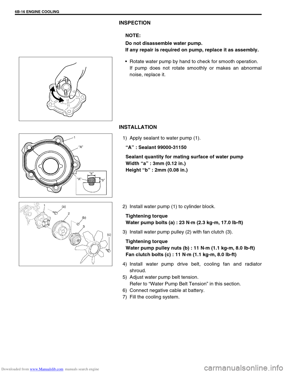
INSTALLATION
1) Apply sealant to water pump (1).
“A” : Sealant 99000-31150
Sealant quantity for mating surface of water pump
Width “a” : 3mm (0.12 in.)
Height “b” : 2mm (0.08 in.)
2) Install water pump (1) to cylinder block.
Tightening torque
Water pump bolts (a) : 23 N·m (2.3 kg-m, 17.0 lb-ft)
3) Install water pump pulley (2) with fan clutch (3).
Tightening torque
Water pump pulley nuts (b) : 11 N·m (1.1 kg-m, 8.0 lb-ft)
Fan clutch bolts (c) : 11 N·m (1.1 kg-m, 8.0 lb-ft)
4) Install water pump drive belt, cooling fan and radiator
shroud.
5) Adjust water pump belt tension.
Refer to “Water Pump Belt Tension” in this section.
6) Connect negative cable at battery.
7) Fill the cooling system.NOTE:
Do not disassemble water pump.
If any repair is required on pump, replace it as assembly.
Page 640 of 687
Downloaded from www.Manualslib.com manuals search engine ENGINE AND EMISSION CONTROL SYSTEM 6E-35
Crankshaft position sensor
INSPECTION
Check crankshaft position sensor referring to step 2 and 6 of
“DTC P0335 (No.23) Flow Table” in Section 6. If malfunction is
found, replace.
REMOVAL
1) Disconnect negative cable at battery.
2) Remove generator drive belt, loosen pivot bolt and move
generator outward.
3) Disconnect connector from crankshaft position sensor.
4) Remove crankshaft position sensor (1) from cylinder block.
INSTALLATION
1) Check to make sure that crankshaft position sensor and pul-
ley tooth is free from any metal particles and damage.
2) Install crankshaft position sensor to cylinder block.
3) Connect connector to it securely.
4) Adjust generator belt tension, refer to “Water Pump Belt Ten-
sion” in Section 6B.
5) Connect negative cable to battery.
Page 673 of 687
Downloaded from www.Manualslib.com manuals search engine 6H-6 CHARGING SYSTEM
Diagnosis
Battery
COMMON CAUSES OF FAILURE
A battery is not designed to last indefinitely; however, with proper
care, it will provide many years of service. If the battery performs
satisfactorily during test but fails to operate properly for no appar-
ent reason, the followings are some factors that may point to the
cause of trouble:
Accessories left on overnight or for an extended period with-
out the generator operating.
Slow average driving speeds for short periods.
Electrical load exceeding generator output particularly with
addition of after market equipment.
Defects in charging system such as high resistance, slipping
drive belt, loose generator output terminal, faulty generator
or voltage regulator. Refer to “Generator” in this “Diagnosis”
section.
Battery abuse, including failure to keep battery cable termi-
nals clean and tight or loose battery hold down.
Mechanical problems in electrical system such as shorted or
pinched wires.
VISUAL INSPECTION
Check for obvious damage, such as cracked or broken case or
cover, that could permit loss of electrolyte. If obvious damage is
noted, replace battery. Determine cause of damage and correct
as needed.
HYDROMETER TEST
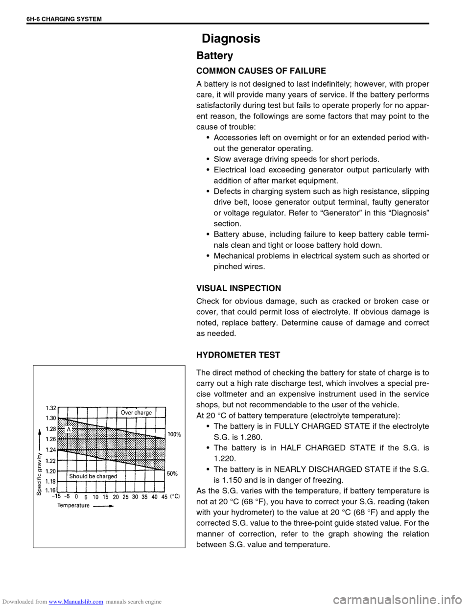
The direct method of checking the battery for state of charge is to
carry out a high rate discharge test, which involves a special pre-
cise voltmeter and an expensive instrument used in the service
shops, but not recommendable to the user of the vehicle.
At 20 °C of battery temperature (electrolyte temperature):
The battery is in FULLY CHARGED STATE if the electrolyte
S.G. is 1.280.
The battery is in HALF CHARGED STATE if the S.G. is
1.220.
The battery is in NEARLY DISCHARGED STATE if the S.G.
is 1.150 and is in danger of freezing.
As the S.G. varies with the temperature, if battery temperature is
not at 20 °C (68 °F), you have to correct your S.G. reading (taken
with your hydrometer) to the value at 20 °C (68 °F) and apply the
corrected S.G. value to the three-point guide stated value. For the
manner of correction, refer to the graph showing the relation
between S.G. value and temperature.
Page 674 of 687
Downloaded from www.Manualslib.com manuals search engine CHARGING SYSTEM 6H-7
How to use the temperature-corrected state-of-charge
graph
Suppose your S.G. reading is 1.28 and the battery temperature is
–5 °C (23 °F). Locate the intersection of the –5 °C line and the
1.28 S.G. line.
The intersection is within the “A” zone (shaded area in the graph)
and that means CHARGED STATE.
To know how much the battery is charged, draw a line parallel to
the zone demarcation line and extend it to the right till it meets
with the percentage scale. In the present example, the line meets
at about 85% point on the percentage scale. Therefore, the bat-
tery is charged up to the 85% level.
Generator
Trouble in charging system will show up as one or more of follow-
ing conditions:
1) Faulty indicator lamp operation.
2) An undercharged battery as evidenced by slow cranking or
indicator dark.
3) An overcharged battery as evidenced by excessive spewing
of electrolyte from vents.
Noise from generator may be caused by a loose drive pulley,
loose mounting bolts, worn or dirty bearings, defective diode, or
defective stator.
FAULTY INDICATOR LAMP OPERATION
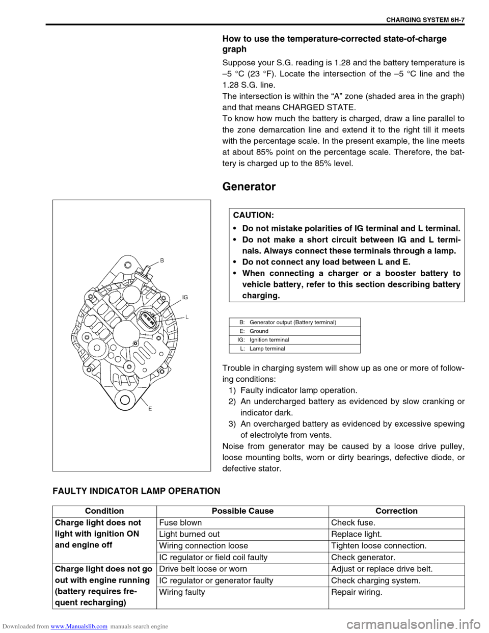
CAUTION:
Do not mistake polarities of IG terminal and L terminal.
Do not make a short circuit between IG and L termi-
nals. Always connect these terminals through a lamp.
Do not connect any load between L and E.
When connecting a charger or a booster battery to
vehicle battery, refer to this section describing battery
charging.
B: Generator output (Battery terminal)
E: Ground
IG: Ignition terminal
L: Lamp terminal
Condition Possible Cause Correction
Charge light does not
light with ignition ON
and engine offFuse blown Check fuse.
Light burned out Replace light.
Wiring connection loose Tighten loose connection.
IC regulator or field coil faulty Check generator.
Charge light does not go
out with engine running
(battery requires fre-
quent recharging)Drive belt loose or worn Adjust or replace drive belt.
IC regulator or generator faulty Check charging system.
Wiring faulty Repair wiring.