2005 SUZUKI JIMNY Engine belt
[x] Cancel search: Engine beltPage 135 of 687

Downloaded from www.Manualslib.com manuals search engine 3B1-4 POWER STEERING (P/S) SYSTEM (If equipped)
Abnormal noise
(See NOTE “D”.)Air drawn in due to insufficient fluid Replenish fluid.
Air drawn in through pipe or hose joints Retighten or replace.
Belt slipping (loose) Adjust.
Worn belt Replace.
Loose steering linkage Retighten.
Loose gear box fixing bolt Retighten.
Loose pitman arm Retighten.
Pipes or hoses in contact with chassis Correct.
Defective pump vane Replace pump assembly.
Malfunction of flow control valve Replace gear box assembly.
Defective pump shaft bearing Replace pump assembly. Condition Possible Cause Correction
NOTE:
“C” : Turn steering wheel 90° at 35 km/h (22 mile/h) and let it free. If it returns more than 60° then, it
is normal.
“D” : Some hissing noise may be heard through steering column when turning steering wheel with
vehicle halted. It is from operation of the valve in the gear box and indicates nothing abnormal.
Page 137 of 687

Downloaded from www.Manualslib.com manuals search engine 3B1-6 POWER STEERING (P/S) SYSTEM (If equipped)
Power Steering Belt Check
INSPECTION
Check that belt is free from any damage and properly fitted
in pulley groove.
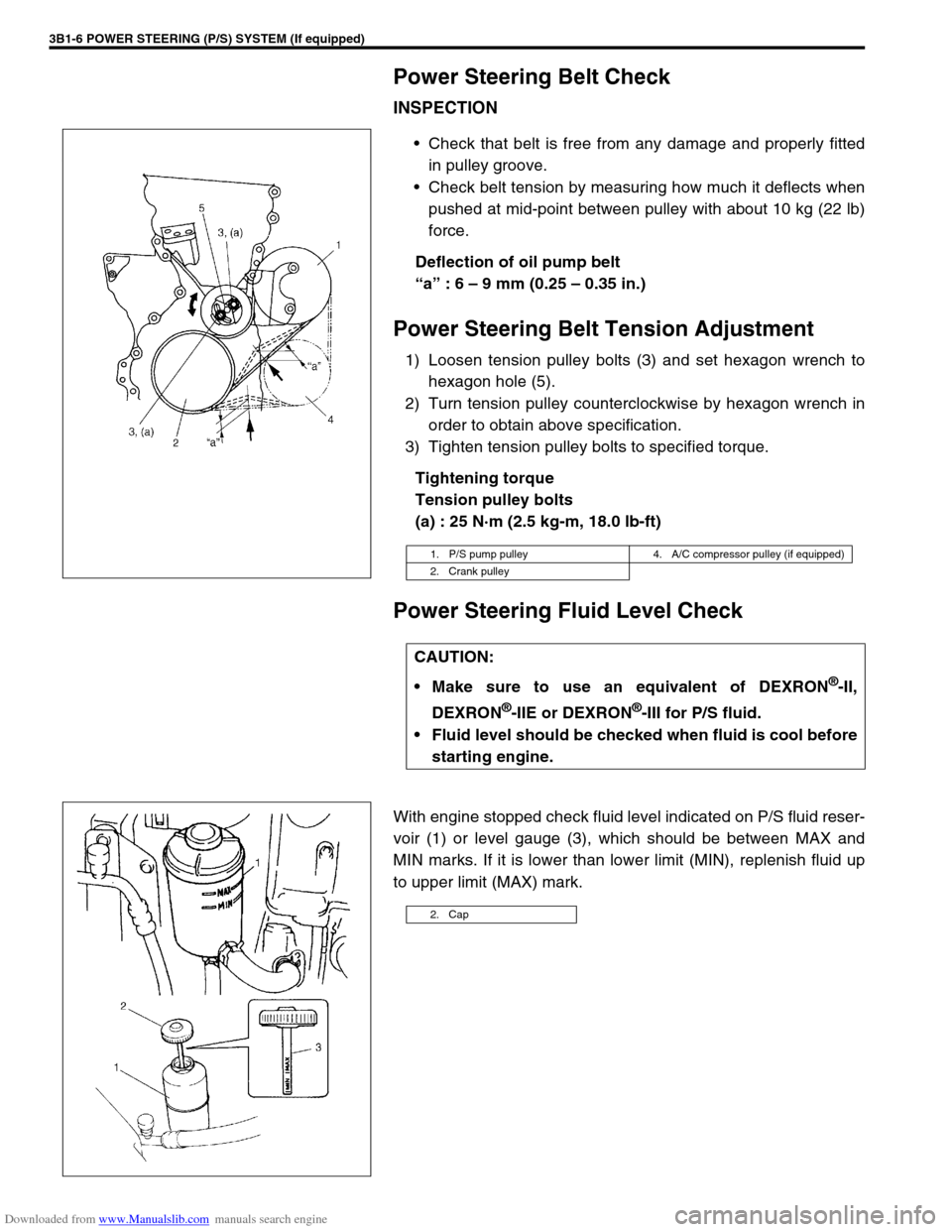
Check belt tension by measuring how much it deflects when
pushed at mid-point between pulley with about 10 kg (22 lb)
force.
Deflection of oil pump belt
“a” : 6 – 9 mm (0.25 – 0.35 in.)
Power Steering Belt Tension Adjustment
1) Loosen tension pulley bolts (3) and set hexagon wrench to
hexagon hole (5).
2) Turn tension pulley counterclockwise by hexagon wrench in
order to obtain above specification.
3) Tighten tension pulley bolts to specified torque.
Tightening torque
Tension pulley bolts
(a) : 25 N·m (2.5 kg-m, 18.0 lb-ft)
Power Steering Fluid Level Check
With engine stopped check fluid level indicated on P/S fluid reser-
voir (1) or level gauge (3), which should be between MAX and
MIN marks. If it is lower than lower limit (MIN), replenish fluid up
to upper limit (MAX) mark.
1. P/S pump pulley 4. A/C compressor pulley (if equipped)
2. Crank pulley
CAUTION:
Make sure to use an equivalent of DEXRON
®-II,
DEXRON
®-IIE or DEXRON®-III for P/S fluid.
Fluid level should be checked when fluid is cool before
starting engine.
2. Cap
Page 143 of 687

Downloaded from www.Manualslib.com manuals search engine 3B1-12 POWER STEERING (P/S) SYSTEM (If equipped)
On-Vehicle Service
Power Steering Belt
REMOVAL
1) Disconnect negative cable at battery.
2) Loosen tension pulley bolts (2).
3) Remove power steering belt (1).
INSPECTION
Check power steering belt for wear and cracks, and replace
as required.
INSTLLATION
1) Install belt to power steering pump pulley (1), crankshaft pul-
ley (2), A/C pulley (if equipped) (3) and tension pulley (4).
2) Adjust belt tension referring to “Power Steering Belt Check”
in this section.
Power Steering (P/S) Pump
REMOVAL
1) Take out fluid in P/S fluid reservoir with syringe or such.
2) Remove P/S belt.
3) Disconnect high pressure hose and low pressure hose.
4) Disconnect pressure switch lead harness.
Page 149 of 687

Downloaded from www.Manualslib.com manuals search engine 3B1-18 POWER STEERING (P/S) SYSTEM (If equipped)
INSTALLATION
Install components in reverse order of removal procedure noting
the following points.
Tighten each bolt as specified below.
Tightening torque
Oil pump mounting bolts
(a) : 25 N·m (2.5 kg-m, 18.5 lb-ft)
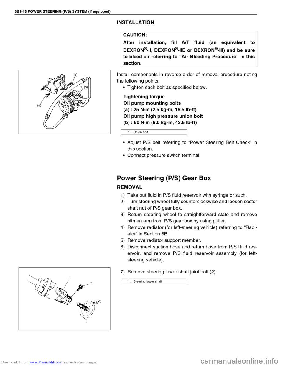
Oil pump high pressure union bolt
(b) : 60 N·m (6.0 kg-m, 43.5 lb-ft)
Adjust P/S belt referring to “Power Steering Belt Check” in
this section.
Connect pressure switch terminal.
Power Steering (P/S) Gear Box
REMOVAL
1) Take out fluid in P/S fluid reservoir with syringe or such.
2) Turn steering wheel fully counterclockwise and loosen sector
shaft nut of P/S gear box.
3) Return steering wheel to straightforward state and remove
pitman arm from P/S gear box by using puller.
4) Remove radiator (for left-steering vehicle) referring to “Radi-
ator” in Section 6B
5) Remove radiator support member.
6) Disconnect suction hose and return hose from P/S fluid res-
ervoir, and remove P/S fluid reservoir assembly (for left-
steering vehicle).
7) Remove steering lower shaft joint bolt (2).CAUTION:
After installation, fill A/T fluid (an equivalent to
DEXRON
®-II, DEXRON®-IIE or DEXRON®-III) and be sure
to bleed air referring to “Air Bleeding Procedure” in this
section.
1. Union bolt
1. Steering lower shaft
Page 155 of 687

Downloaded from www.Manualslib.com manuals search engine 3C-2 STEERING WHEEL AND COLUMN
General Description
This double tube type steering column has the following three important features in addition to the steering func-
tion:
The column is energy absorbing, designed to compress in a front-end collision.
The ignition switch and lock are mounted conveniently on this column.
With the column mounted lock, the ignition and steering operations can be locked to inhibit theft of the vehi-
cle.
To insure the energy absorbing action, it is important that only the specified screws, bolts and nuts be used as
designated and that they are tightened to the specified torque.
When the column assembly is removed from the vehicle, special care must be taken in handling it. Use of a
steering wheel puller other than the one recommended in this manual or a sharp blow on the end of the steering
shaft, leaning on the assembly, or dropping the assembly could shear the plastic shear pins which maintain col-
umn length and position.
The driver air bag (inflator) module is one of the supplemental restraint (air bag) system components and is
mounted to the center of the steering wheel. During certain frontal crashes, the air bag system supplements the
restraint of the driver’s and passenger’s seat belts by deploying the air bags.
The air bag (inflator) module should be handled with care to prevent accidental deployment. When servicing, be
sure to observe all WARNINGS and CAUTIONS in this section and “Service Precautions” in Section 10B.
1. Driver air bag (inflator) module 6. Steering column upper cover 11. Steering lower shaft
2. Steering wheel 7. Steering column lower cover [A] : For vehicle with air bag system
3. Steering wheel side cap 8. Steering column assembly [B] : For vehicle without air bag system
4. Steering wheel nut 9. Steering lock assembly (ignition switch)
5. Combination switch or contact coil and com-
bination switch assembly10. Steering column hole cover
Page 245 of 687

Downloaded from www.Manualslib.com manuals search engine 3F-2 WHEELS AND TIRES
General Description
Tires
This vehicle is equipped with following tire.
Tire size
: 205/70 R15 or 175/80 R15
The tires are of tubeless type. The tires are designed to operate satisfactorily with loads up to the full rated load
capacity when inflated to the recommended inflation pressure.
Correct tire pressures and driving habits have an important influence on tire life Heavy cornering, excessively
rapid acceleration, and unnecessary sharp braking increase tire wear.
Wheels
Standard equipment wheels are following steel wheels.
15 x 5 1/2 JJ
Replacement Tires
When replacement is necessary, the original equipment type tire should be used. Refer to the Tire Placard.
Replacement tires should be of the same size, load range and construction as those originally on the vehicle.
Use of any other size or type tire may affect ride, handling, speedometer / odometer calibration, vehicle ground
clearance and tire or snow chain clearance to the body and chassis.
It is recommended that new tires be installed in pairs on the same axle. If necessary to replace only one tire, it
should be paired with the tire having the most tread, to equalize braking traction.
The metric term for tire inflation pressure is the kilopascal (kPa).
Tire pressures will usually be printed in both kPa and psi on the
Tire Placard. Metric tire gauges are available from tool suppliers.
The following chart, converts commonly used inflation pressures
from kPa to psi. WARNING:
Do not mix different types of tires on the same vehicle such as radial, bias and bias-belted tires except
in emergencies, because vehicle handling may be seriously affected and may result in loss of control.
kPa
kgf/cm2psi
160
180
200
220
240
260
280
300
320
3401.6
1.8
2.0
2.2
2.4
2.6
2.8
3.0
3.2
3.423
26
29
32
35
38
41
44
47
50
Page 377 of 687

Downloaded from www.Manualslib.com manuals search engine 6-20 ENGINE GENERAL INFORMATION AND DIAGNOSIS
Visual inspection
Visually check following parts and systems.
INSPECTION ITEM REFERRING SECTION
Engine oil – level, leakage Section 0B
Engine coolant – level, leakage Section 0B
Fuel – level, leakage Section 0B
A/T fluid – level, leakage Section 0B
Air cleaner element – dirt, clogging Section 0B
Battery – fluid level, corrosion of terminal
Water pump belt – tension, damage Section 0B
Throttle cable – play, installation
Section 6E Vacuum hoses of air intake system – disconnection, looseness,
deterioration, bend
Connectors of electric wire harness – disconnection, friction
Fuses – burning Section 8
Parts – installation, bolt – looseness
Parts – deformation
Other parts that can be checked visually
Also check following items at engine start, if possible
Malfunction indicator lamp – operation Section 6
Charge warning lamp – operation Section 6H
Engine oil pressure warning lamp – operation Section 8 (Section 6 for pressure check)
Engine coolant temp. meter – operation Section 8
Fuel level meter – operation Section 8
Tachometer, if equipped – operation
Abnormal air being inhaled from air intake system
Exhaust system – leakage of exhaust gas, noise
Other parts that can be checked visually
Page 382 of 687

Downloaded from www.Manualslib.com manuals search engine ENGINE GENERAL INFORMATION AND DIAGNOSIS 6-25
Excessive detonation
(The engine makes
sharp metallic knocks
that change with throt-
tle opening.
Sounds like pop corn
popping.)Engine overheating Refer to “Overheating” of this table.
Faulty spark plug Spark plugs in Section 6F.
Clogged fuel filter and fuel lines Diagnostic Flow Table B-3
Malfunctioning EGR valve (if equipped) EGR system in Section 6E.
Poor performance of knock sensor, ECT
sensor or MAP sensorKnock sensor in this section, ECT
sensor or MAP sensor in Section 6E.
Faulty injector Diagnostic Flow Table B-1
Faulty ECM Inspection of ECM and its circuit in
this section.
Excessive combustion chamber deposits Piston and cylinder head in Section
6A1.
Overheating
Inoperative thermostat Thermostat in Section 6B.
Faulty A/C condenser fan motor or its cir-
cuitA/C condenser fan control system
check in Section 6E.
Loose or slip water pump belt ITEM1-1 Drive belt inspection and
change in Section 0B.
Poor water pump performance Water pump in Section 6B.
Clogged or leaky radiator Radiator in Section 6B.
Improper engine oil grade ITEM1-3 Engine oil and oil filter
change in Section 0B.
Clogged oil filter or oil strainer Oil pressure check in Section 6A1.
Poor oil pump performance Oil pressure check in Section 6A1.
Dragging brakes Diagnosis Table in Section 5.
Slipping clutch Diagnosis Table in Section 7C.
Blown cylinder head gasket Valves and cylinder head in Section
6A1.
Poor gasoline mileage
Faulty ignition coil Ignition coil assembly in Section 6F.
Fuel pressure out of specification Diagnostic Flow Table B-3
Faulty TP sensor, ECT sensor or MAP
sensorTP sensor, ECT sensor or MAP sen-
sor in Section 6E.
Faulty injector Diagnostic Flow Table B-1
Faulty ECM Inspection of ECM and its circuit in
this section.
Malfunctioning EGR valve (if equipped) EGR system in Section 6E.
High idle speed Refer to item “Improper Engine Idle
Speed” previously outlined.
Low compression Previously outlined.
Poor valve seating Valves and cylinder head in Section
6A1.
Dragging brakes Diagnosis Table in Section 5.
Slipping clutch Diagnosis Table in Section 7C.
Thermostat out of order Thermostat in Section 6B.
Improper tire pressure Refer to Section 3F. Condition Possible Cause Reference Item