2005 SUZUKI JIMNY Engine belt
[x] Cancel search: Engine beltPage 614 of 687

Downloaded from www.Manualslib.com manuals search engine ENGINE AND EMISSION CONTROL SYSTEM 6E-9
ECM INPUT / OUTPUT CIRCUIT DIAGRAM
For TYPE A (See NOTE)
NOTE:
Type A is other than follows.
Type B is left hand steering vehicle equipped with fasten seat belt light and EGR valve or right hand
steering vehicle equipped with fasten seat belt light and immobilizer control system.
Page 640 of 687

Downloaded from www.Manualslib.com manuals search engine ENGINE AND EMISSION CONTROL SYSTEM 6E-35
Crankshaft position sensor
INSPECTION
Check crankshaft position sensor referring to step 2 and 6 of
“DTC P0335 (No.23) Flow Table” in Section 6. If malfunction is
found, replace.
REMOVAL
1) Disconnect negative cable at battery.
2) Remove generator drive belt, loosen pivot bolt and move
generator outward.
3) Disconnect connector from crankshaft position sensor.
4) Remove crankshaft position sensor (1) from cylinder block.
INSTALLATION
1) Check to make sure that crankshaft position sensor and pul-
ley tooth is free from any metal particles and damage.
2) Install crankshaft position sensor to cylinder block.
3) Connect connector to it securely.
4) Adjust generator belt tension, refer to “Water Pump Belt Ten-
sion” in Section 6B.
5) Connect negative cable to battery.
Page 668 of 687

Downloaded from www.Manualslib.com manuals search engine CHARGING SYSTEM 6H-1
6F1
6F2
6G
6K
7D
7E
7F
7C1
7D
7E
7F
8A
8B
8C
8D
8E
9
7A
6H
7B1
10B
SECTION 6H
CHARGING SYSTEM
CONTENTS
General Description ....................................... 6H-2
Battery .......................................................... 6H-2
Generator ..................................................... 6H-4
Diagnosis ........................................................ 6H-6
Battery .......................................................... 6H-6
Generator ..................................................... 6H-7
On-Vehicle Service......................................... 6H-9
Battery .......................................................... 6H-9
Jump starting in case of emergency......... 6H-9
Dismounting ........................................... 6H-11
Handling ................................................. 6H-11
Remounting ............................................ 6H-11Generator ................................................... 6H-11
Generator belt ........................................ 6H-11
Unit Repair Overhaul ................................... 6H-12
Generator ................................................... 6H-12
Dismounting ........................................... 6H-12
Remounting ............................................ 6H-13
Disassembly and reassembly ................ 6H-13
Inspection ............................................... 6H-14
Specifications............................................... 6H-17
Battery........................................................ 6H-17
Generator ................................................... 6H-17
Tightening Torque Specification ................ 6H-17
WARNING:
For vehicles equipped with Supplemental Restraint (Air Bag) System
Service on and around the air bag system components or wiring must be performed only by an
authorized SUZUKI dealer. Refer to “Air Bag System Components and Wiring Location View” under
“General Description” in air bag system section in order to confirm whether you are performing ser-
vice on or near the air bag system components or wiring. Please observe all WARNINGS and “Ser-
vice Precautions” under “On-Vehicle Service” in air bag system section before performing service
on or around the air bag system components or wiring. Failure to follow WARNINGS could result in
unintentional activation of the system or could render the system inoperative. Either of these two
conditions may result in severe injury.
Technical service work must be started at least 90 seconds after the ignition switch is turned to the
“LOCK” position and the negative cable is disconnected from the battery. Otherwise, the system
may be activated by reserve energy in the Sensing and Diagnostic Module (SDM).
Page 673 of 687

Downloaded from www.Manualslib.com manuals search engine 6H-6 CHARGING SYSTEM
Diagnosis
Battery
COMMON CAUSES OF FAILURE
A battery is not designed to last indefinitely; however, with proper
care, it will provide many years of service. If the battery performs
satisfactorily during test but fails to operate properly for no appar-
ent reason, the followings are some factors that may point to the
cause of trouble:
Accessories left on overnight or for an extended period with-
out the generator operating.
Slow average driving speeds for short periods.
Electrical load exceeding generator output particularly with
addition of after market equipment.
Defects in charging system such as high resistance, slipping
drive belt, loose generator output terminal, faulty generator
or voltage regulator. Refer to “Generator” in this “Diagnosis”
section.
Battery abuse, including failure to keep battery cable termi-
nals clean and tight or loose battery hold down.
Mechanical problems in electrical system such as shorted or
pinched wires.
VISUAL INSPECTION
Check for obvious damage, such as cracked or broken case or
cover, that could permit loss of electrolyte. If obvious damage is
noted, replace battery. Determine cause of damage and correct
as needed.
HYDROMETER TEST
The direct method of checking the battery for state of charge is to
carry out a high rate discharge test, which involves a special pre-
cise voltmeter and an expensive instrument used in the service
shops, but not recommendable to the user of the vehicle.
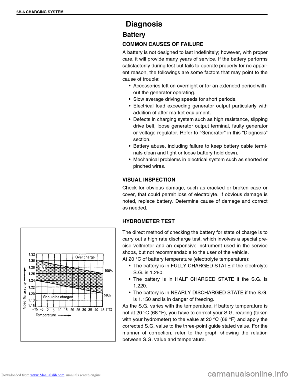
At 20 °C of battery temperature (electrolyte temperature):
The battery is in FULLY CHARGED STATE if the electrolyte
S.G. is 1.280.
The battery is in HALF CHARGED STATE if the S.G. is
1.220.
The battery is in NEARLY DISCHARGED STATE if the S.G.
is 1.150 and is in danger of freezing.
As the S.G. varies with the temperature, if battery temperature is
not at 20 °C (68 °F), you have to correct your S.G. reading (taken
with your hydrometer) to the value at 20 °C (68 °F) and apply the
corrected S.G. value to the three-point guide stated value. For the
manner of correction, refer to the graph showing the relation
between S.G. value and temperature.
Page 674 of 687

Downloaded from www.Manualslib.com manuals search engine CHARGING SYSTEM 6H-7
How to use the temperature-corrected state-of-charge
graph
Suppose your S.G. reading is 1.28 and the battery temperature is
–5 °C (23 °F). Locate the intersection of the –5 °C line and the
1.28 S.G. line.
The intersection is within the “A” zone (shaded area in the graph)
and that means CHARGED STATE.
To know how much the battery is charged, draw a line parallel to
the zone demarcation line and extend it to the right till it meets
with the percentage scale. In the present example, the line meets
at about 85% point on the percentage scale. Therefore, the bat-
tery is charged up to the 85% level.
Generator
Trouble in charging system will show up as one or more of follow-
ing conditions:
1) Faulty indicator lamp operation.
2) An undercharged battery as evidenced by slow cranking or
indicator dark.
3) An overcharged battery as evidenced by excessive spewing
of electrolyte from vents.
Noise from generator may be caused by a loose drive pulley,
loose mounting bolts, worn or dirty bearings, defective diode, or
defective stator.
FAULTY INDICATOR LAMP OPERATION
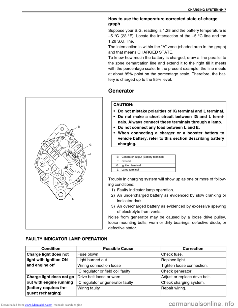
CAUTION:
Do not mistake polarities of IG terminal and L terminal.
Do not make a short circuit between IG and L termi-
nals. Always connect these terminals through a lamp.
Do not connect any load between L and E.
When connecting a charger or a booster battery to
vehicle battery, refer to this section describing battery
charging.
B: Generator output (Battery terminal)
E: Ground
IG: Ignition terminal
L: Lamp terminal
Condition Possible Cause Correction
Charge light does not
light with ignition ON
and engine offFuse blown Check fuse.
Light burned out Replace light.
Wiring connection loose Tighten loose connection.
IC regulator or field coil faulty Check generator.
Charge light does not go
out with engine running
(battery requires fre-
quent recharging)Drive belt loose or worn Adjust or replace drive belt.
IC regulator or generator faulty Check charging system.
Wiring faulty Repair wiring.
Page 675 of 687

Downloaded from www.Manualslib.com manuals search engine 6H-8 CHARGING SYSTEM
UNDERCHARGED BATTERY
This condition, as evidenced by slow cranking or indicator clear
with red dot can be caused by one or more of the following condi-
tions even though indicator lamp may be operating normal.
Following procedure also applies to cars with voltmeter and
ammeter.
1) Make sure that undercharged condition has not been caused
by accessories left on for extended period of time.
2) Check drive belt for proper tension.
3) If battery defect is suspected, refer to BATTERY section.
4) Inspect wiring for defects. Check all connections for tight-
ness and cleanliness, battery cable connections at battery,
starting motor and ignition ground cable.
5) Connect voltmeter and ammeter as shown in the figure.
6) Measure current and voltage.
No-load Check
1) Run engine from idling up to 2,000 rpm and read meters.
Standard current
10 A maximum
Standard voltage
14.4 – 15.0 V (at 20 °C, 68 °F)
Higher Voltage
If voltage is higher than standard value, check ground of brushes.
If brushes are not grounded, replace IC regulator.
Lower Voltage
If voltage is below or in standard value, increase engine speed up
to 2,000 – 2,500 rpm soon after starting engine, and read maxi-
mum value on ammeter immediately.
If current is less than 49 A, repair or replace generator.NOTE:
Use fully charged battery.
1. Generator
2. Ammeter (between generator (B) terminal and battery (+) terminal)
3. Voltmeter (between generator (B) terminal and ground)
4. Battery
5. Load
6. Switch
NOTE:
Turn off switches of all accessories (wiper, heater etc.).
NOTE:
Consideration should be taken that voltage will differ
somewhat with regulator case temperature as shown in
the graph.
Page 678 of 687

Downloaded from www.Manualslib.com manuals search engine CHARGING SYSTEM 6H-11
Dismounting
1) Disconnect negative cable (3).
2) Disconnect positive cable (2).
3) Remove retainer (5).
4) Remove battery (1).
Handling
When handling battery, following safety precautions should be
followed:
Hydrogen gas is produced by battery. A flame or spark near
battery may cause the gas to ignite.
Battery fluid is highly acidic. Avoid spilling on clothing or
other fabric. Any spilled electrolyte should be flushed with
large quantity of water and cleaned immediately.
Remounting
1) Reverse removal procedure.
2) Torque battery cables to specification.
Tightening torque
Body ground bolt (a) : 8.0 N·m (0.8 kg-m, 6.0 lb-ft)
Generator
Generator belt
Refer to “Water Pump Belt and Cooling Fan” in Section 6B.
4. Body ground bolt
NOTE:
Check to be sure that ground cable has enough clear-
ance to hood panel by terminal.
Page 679 of 687

Downloaded from www.Manualslib.com manuals search engine 6H-12 CHARGING SYSTEM
Unit Repair Overhaul
Generator
Dismounting
1) Disconnect negative (–) cable (2) at battery (1).
2) Remove bolts (2) and then canister (1) together with its
bracket.
3) Disconnect “B” terminal wire (3) and coupler (2) from gener-
ator (1).
4) Remove generator belt. Refer to “Water Pump Belt and
Cooling Fan” in Section 6B.
5) Remove generator.
1. Generator adjusting bolt
2. Generator pivot bolt
3.“B” terminal