Page 211 of 687
Downloaded from www.Manualslib.com manuals search engine 3D-38 FRONT SUSPENSION
Front Axle Housing
REMOVAL
1) Hoist vehicle.
2) Remove front wheels.
3) Drain front differential gear oil (for 4WD).
4) Remove caliper carrier bolts (R&L) and suspend caliper.
5) Remove right and left brake disc.
6) Remove wheel speed sensor (if equipped with ABS).
7) Disconnect spindle vacuum hoses from wheel spindle (for
4WD).
8) Remove tie rod (and drag rod) end nuts and disconnect tie
rod (and drag rod) ends (2) from knuckle arm (1) (R&L) with
special tool.
Special tool
(A) : 09913-65210 CAUTION:
During removal, be careful not to damage brake flexible
hose and not to depress brake pedal.
NOTE:
If brake disc can not be removed by hand, use 8mm bolts
(1).
CAUTION:
Give match mark to spindle vacuum hose and wheel
spindle before removal.
1. Vacuum hose to lock
2. Vacuum hose to unlock
Page 215 of 687

Downloaded from www.Manualslib.com manuals search engine 3D-42 FRONT SUSPENSION
9) Install right and left axle shafts to axle housing (for 4WD).
Install knuckle to axle housing (for 2WD).
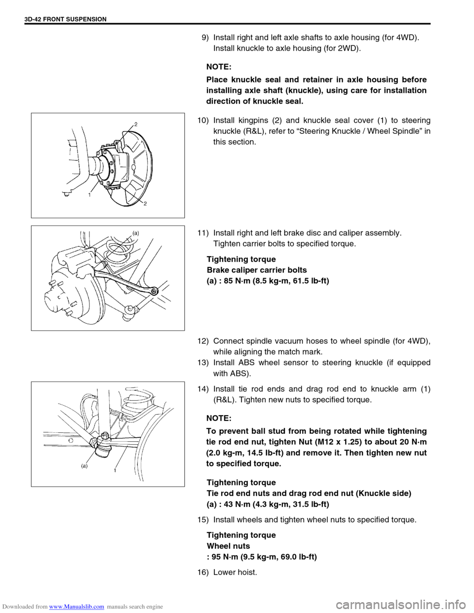
10) Install kingpins (2) and knuckle seal cover (1) to steering
knuckle (R&L), refer to “Steering Knuckle / Wheel Spindle” in
this section.
11) Install right and left brake disc and caliper assembly.
Tighten carrier bolts to specified torque.
Tightening torque
Brake caliper carrier bolts
(a) : 85 N·m (8.5 kg-m, 61.5 lb-ft)
12) Connect spindle vacuum hoses to wheel spindle (for 4WD),
while aligning the match mark.
13) Install ABS wheel sensor to steering knuckle (if equipped
with ABS).
14) Install tie rod ends and drag rod end to knuckle arm (1)
(R&L). Tighten new nuts to specified torque.
Tightening torque
Tie rod end nuts and drag rod end nut (Knuckle side)
(a) : 43 N·m (4.3 kg-m, 31.5 lb-ft)
15) Install wheels and tighten wheel nuts to specified torque.
Tightening torque
Wheel nuts
: 95 N·m (9.5 kg-m, 69.0 lb-ft)
16) Lower hoist.NOTE:
Place knuckle seal and retainer in axle housing before
installing axle shaft (knuckle), using care for installation
direction of knuckle seal.
NOTE:
To prevent ball stud from being rotated while tightening
tie rod end nut, tighten Nut (M12 x 1.25) to about 20 N·m
(2.0 kg-m, 14.5 Ib-ft) and remove it. Then tighten new nut
to specified torque.
Page 229 of 687
Downloaded from www.Manualslib.com manuals search engine 3E-10 REAR SUSPENSION
INSTALLATION
1) Install lateral rod to vehicle body and rear axle housing.
Tighten bolt and nut temporarily by hand.
2) Lower hoist and with vehicle in non-loaded condition, tighten
lateral rod bolt and nut to specified torque.
Tightening torque
Lateral rod bolt and nut
(a) : 90 N·m (9.0 kg-m, 65.0 lb-ft)
Trailing Arm / Bushing
REMOVAL
1) Hoist vehicle.
2) Support rear axle housing (1) by using floor jack (2).
3) Disconnect parking brake cable clamp (1) from trailing arm.
4) Disconnect wheel speed sensor harness clamps (2) from
trailing arm (if equipped with ABS).
5) Remove trailing arm mounting bolts.
6) Remove trailing arm (1).
Page 231 of 687

Downloaded from www.Manualslib.com manuals search engine 3E-12 REAR SUSPENSION
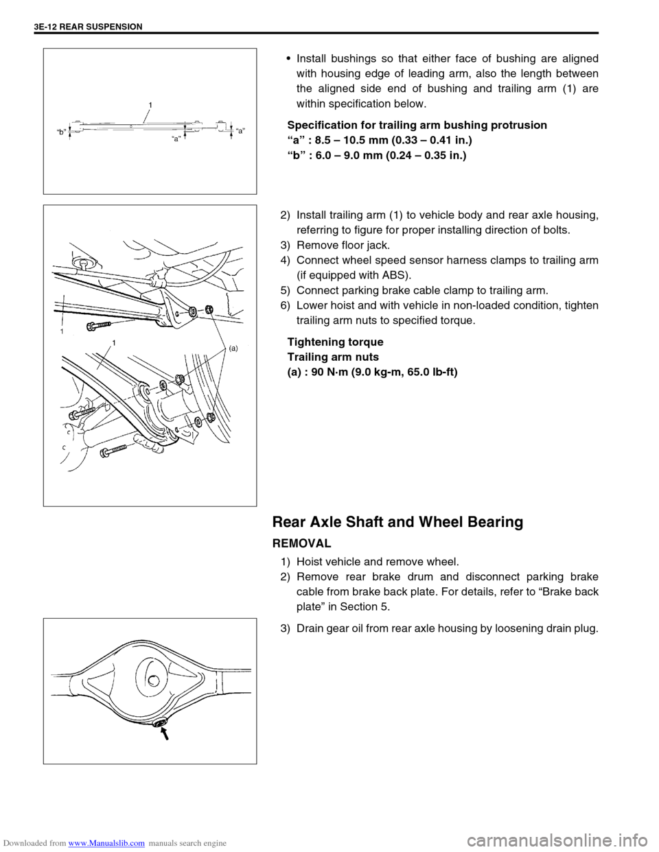
Install bushings so that either face of bushing are aligned
with housing edge of leading arm, also the length between
the aligned side end of bushing and trailing arm (1) are
within specification below.
Specification for trailing arm bushing protrusion
“a” : 8.5 – 10.5 mm (0.33 – 0.41 in.)
“b” : 6.0 – 9.0 mm (0.24 – 0.35 in.)
2) Install trailing arm (1) to vehicle body and rear axle housing,
referring to figure for proper installing direction of bolts.
3) Remove floor jack.
4) Connect wheel speed sensor harness clamps to trailing arm
(if equipped with ABS).
5) Connect parking brake cable clamp to trailing arm.
6) Lower hoist and with vehicle in non-loaded condition, tighten
trailing arm nuts to specified torque.
Tightening torque
Trailing arm nuts
(a) : 90 N·m (9.0 kg-m, 65.0 lb-ft)
Rear Axle Shaft and Wheel Bearing
REMOVAL
1) Hoist vehicle and remove wheel.
2) Remove rear brake drum and disconnect parking brake
cable from brake back plate. For details, refer to “Brake back
plate” in Section 5.
3) Drain gear oil from rear axle housing by loosening drain plug.
Page 232 of 687

Downloaded from www.Manualslib.com manuals search engine REAR SUSPENSION 3E-13
4) Remove wheel speed sensor (4) from rear axle housing (if
equipped with ABS).
5) Disconnect brake pipe(s) (2) from wheel cylinder and put
wheel cylinder bleeder plug cap (1) onto pipe to prevent fluid
from spilling.
6) Remove brake back plate nuts (3) from axle housing.
7) Using special tools indicated, draw out axle shaft with brake
back plate.
Special tool
(A) : 09942-15510
(B) : 09943-35511 or 09943-35512
8) If equipped with ABS, in order to remove sensor rotor from
retainer ring, grind with a grinder one part of the sensor rotor
as illustrated till it becomes thin.
9) Break with a chisel the thin ground sensor rotor, and it can
be removed (if equipped with ABS). CAUTION:
Do not pull wire harness or twist more than necessary
when removing rear wheel speed sensor (4).
Do not cause damage to surface of rear wheel speed
sensor (4) or pole piece and do not allow dust, etc. to
enter its installation hole.
Page 234 of 687

Downloaded from www.Manualslib.com manuals search engine REAR SUSPENSION 3E-15
INSTALLATION
Install removed parts in reverse order of removal procedure, not-
ing the following.
1) Aligning serrations between new stud bolt(s) (1) and flange,
install new stud bolt(s) (1) by tightening nut (2) as shown.
2) Press-fit wheel bearing (1) and retainer ring (2) as shown.
3) For vehicle with ABS, press-fit new sensor rotor as shown.
4) Inspect axle shaft length.
Rear axle shaft length
“a” : 775.5 mm (30.5 in.) (left side),
559.5 mm (22.0 in.) (right side)
5) Apply grease to axle shaft oil seal lip (1) as shown.
“A” : Grease 99000-25010
6) Apply sealant to mating surface of axle housing (2) with
brake back plate.
“B” : Sealant 99000-31110
3. Washer
4. Flange of axle shaft
NOTE:
Use care not to cause any damage to outside of
retainer ring (2).
Refer to figure so that wheel bearing (1) is installed in
proper direction.
NOTE:
Use care not to cause any damage to outside of retainer
ring (2).
[A]: Vehicle without ABS
[B]: Vehicle with ABS
NOTE:
Make sure to remove old sealant before applying it anew.
Page 235 of 687

Downloaded from www.Manualslib.com manuals search engine 3E-16 REAR SUSPENSION
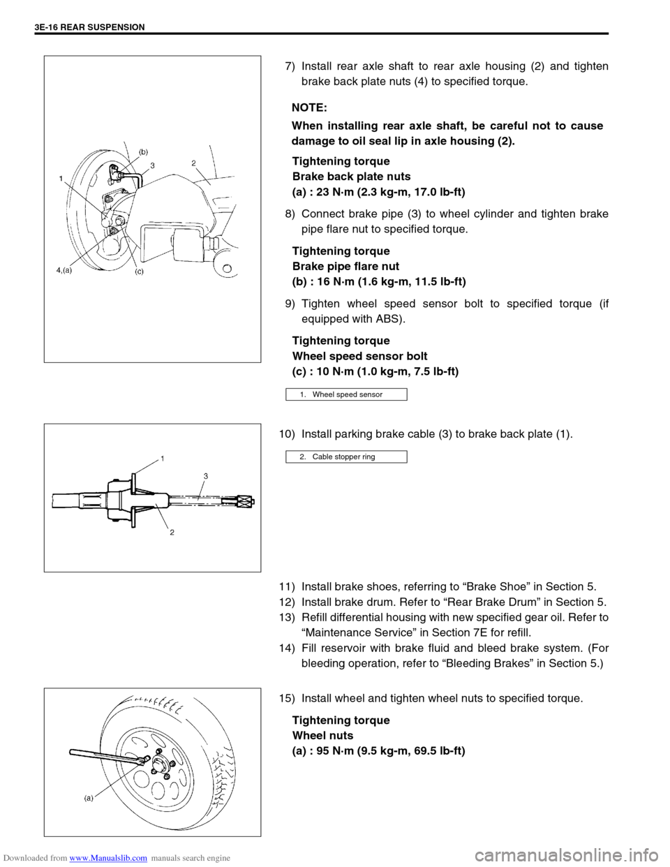
7) Install rear axle shaft to rear axle housing (2) and tighten
brake back plate nuts (4) to specified torque.
Tightening torque
Brake back plate nuts
(a) : 23 N·m (2.3 kg-m, 17.0 lb-ft)
8) Connect brake pipe (3) to wheel cylinder and tighten brake
pipe flare nut to specified torque.
Tightening torque
Brake pipe flare nut
(b) : 16 N·m (1.6 kg-m, 11.5 lb-ft)
9) Tighten wheel speed sensor bolt to specified torque (if
equipped with ABS).
Tightening torque
Wheel speed sensor bolt
(c) : 10 N·m (1.0 kg-m, 7.5 lb-ft)
10) Install parking brake cable (3) to brake back plate (1).
11) Install brake shoes, referring to “Brake Shoe” in Section 5.
12) Install brake drum. Refer to “Rear Brake Drum” in Section 5.
13) Refill differential housing with new specified gear oil. Refer to
“Maintenance Service” in Section 7E for refill.
14) Fill reservoir with brake fluid and bleed brake system. (For
bleeding operation, refer to “Bleeding Brakes” in Section 5.)
15) Install wheel and tighten wheel nuts to specified torque.
Tightening torque
Wheel nuts
(a) : 95 N·m (9.5 kg-m, 69.5 lb-ft) NOTE:
When installing rear axle shaft, be careful not to cause
damage to oil seal lip in axle housing (2).
1. Wheel speed sensor
2. Cable stopper ring
Page 241 of 687

Downloaded from www.Manualslib.com manuals search engine 3E-22 REAR SUSPENSION
Tightening Torque Specifications
Required Service Materials
Fastening portionTightening torque
Nm kg-m lb-ft
Shock absorber upper and lower bolt 85 8.5 61.5
Bump stopper 50 5.0 36.5
Lateral rod bolt and nut
90 9.0 65.0
Trailing arm nut (Front and Rear)
Brake back plate nut 23 2.3 17.0
Brake pipe flare nut 16 1.6 11.5
Rear differential carrier bolt 23 2.3 17.0
Rear propeller shaft bolt (Differential case side) 50 5.0 36.5
Rear propeller shaft bolt (Shaft No.3 transfer case side) 33 3.3 24.0
Wheel nut 95 9.5 69.0
Wheel speed sensor bolt and harness clamp bolt 10 1.0 7.5
MaterialRecommended SUZUKI product
(Part Number)Use
Lithium greaseSUZUKI SUPER GREASE A
(99000-25010)Oil seal lip
SealantSUZUKI BOND NO. 1215
(99000-31110)Joint seam of differential carrier and
axle housing
Water tight sealantSEALING COMPOUND 366E
(99000-31090)To apply to mating surfaces of brake
back plate and rear axle.
Gear oilFor gear oil information, refer to “Mainte-
nance Service” in Section 7E of this manual.Differential gear
(Rear axle housing)