2005 SUZUKI JIMNY Motor
[x] Cancel search: MotorPage 79 of 687
![SUZUKI JIMNY 2005 3.G Service Workshop Manual Downloaded from www.Manualslib.com manuals search engine 1B-18 AIR CONDITIONING (OPTIONAL)
Terminal arrangement of ECM coupler (Viewed from harness side)
1. Blower fan motor 8. Compressor [A]: To “A SUZUKI JIMNY 2005 3.G Service Workshop Manual Downloaded from www.Manualslib.com manuals search engine 1B-18 AIR CONDITIONING (OPTIONAL)
Terminal arrangement of ECM coupler (Viewed from harness side)
1. Blower fan motor 8. Compressor [A]: To “A](/manual-img/20/7588/w960_7588-78.png)
Downloaded from www.Manualslib.com manuals search engine 1B-18 AIR CONDITIONING (OPTIONAL)
Terminal arrangement of ECM coupler (Viewed from harness side)
1. Blower fan motor 8. Compressor [A]: To “A/C” fuse (25A) in main fuse box
2. Dual pressure switch 9. Thermal switch [B]: To “HEATER” fuse (20A) in circuit fuse box
3. A/C switch 10. Main relay [C]: To “FI” fuse (15A) in main fuse box
4. A/C evaporator thermistor 11. Engine earth [D]: 4WD model
5. ECT sensor 12. Blower fan motor switch [E]: 2WD model
6. Condenser cooling fan motor relay 13. 4WD controller
7. Condenser cooling fan motor 14. ECM
Page 80 of 687

Downloaded from www.Manualslib.com manuals search engine AIR CONDITIONING (OPTIONAL) 1B-19
ECM VOLTAGE VALUES TABLE FOR RELATION OF A/C CONTROL
Terminal Wire CircuitMeasurement
groundNormal value Condition
E18-1 PCompressor
magnet clutch
outputGround to
engine (Fig B)10 – 14 voltBlower fan motor switch and A/C
switch ON with engine running
0 – 1 voltsExcept the above-mentioned condi-
tion with engine running
E18-5 Bl/BMain power sup-
ply for ECMGround to
engine (Fig B)10 – 14 voltsIgnition switch ON with engine
stopped
E18-6 Bl/BMain power sup-
ply for ECMGround to
engine (Fig B)10 – 14 voltsIgnition switch ON with engine
stopped
E18-10 Bl Main relay driveGround to
engine (Fig B)0.5 – 1.2 voltIgnition switch ON with engine
stopped
0 volts Ignition switch OFF
E18-16 G/W A/C switch inputGround to
engine (Fig B)12 – 15 voltsBlower fan motor switch or A/C switch
OFF with engine running
0 – 1 voltBlower fan motor switch and A/C
switch ON with engine running
12 – 15 voltsWithin several seconds after operate
transfer lever between 2WD and 4WD
with above condition
E18-18 P/BCompressor
cooling fan relay
outputGround to
engine (Fig B)0 – 1 voltBlower fan motor switch and A/C
switch ON or engine coolant tempera-
ture at more than 110 °C (230 °F) with
engine running.
12 – 15 voltsExcept the above-mentioned condi-
tion with engine running
E18-20 B/BlSensor ground
for A/C evapora-
torGround to
body (Fig A)–0.5 – 0 volt Engine running
E18-24 Bl/YBlower fan
speed inputGround to
engine (Fig B)0 – 1 voltBlower fan motor switch 2nd or 3rd
with engine running
4 – 7 voltsBlower fan motor switch 1st with
engine running
12 – 15 voltsBlower fan motor switch and A/C
switch OFF with engine running
E19-1 BMain ground for
ECMGround to
engine (Fig A)–0.5 – 1 volt Engine running
E19-2 B/RECM ground for
power circuitGround to
engine (Fig A)–0.5 – 1 volt Engine running
E19-3 B/RECM ground for
power circuitGround to
engine (Fig A)–0.5 – 1 volt Engine running
E19-10 B/BlSensor ground
for ECT sensorGround to
body (Fig A)–0.5 – 1 volt Engine running
Page 92 of 687

Downloaded from www.Manualslib.com manuals search engine AIR CONDITIONING (OPTIONAL) 1B-31
Condenser Assembly
INSPECTION
Check the following.
Check clog of condenser fins.
If, any clogs are found, condenser fins should be washed
with water, and should be dried with compressed air.
Check condenser fins for leakage and breakage.
If any defects are found, repair or replace condenser.
Check condenser fittings for leakage.
If any defects are found, repair or replace condenser.
REMOVAL
1) Disconnect negative (–) cable at battery.
2) Recover refrigerant from A/C system by referring to “Recov-
ery” in this section.
3) Remove front bumper referring to “Front Bumper” in Section
8.
4) Disconnect A/C condenser cooling fan motor and dual pres-
sure switch connectors.
5) Remove radiator mounting bolts.
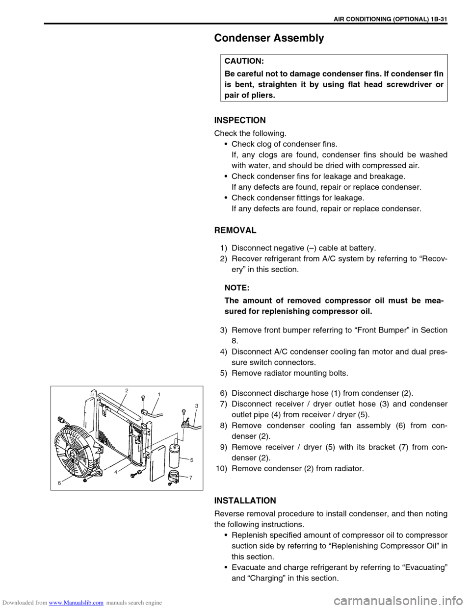
6) Disconnect discharge hose (1) from condenser (2).
7) Disconnect receiver / dryer outlet hose (3) and condenser
outlet pipe (4) from receiver / dryer (5).
8) Remove condenser cooling fan assembly (6) from con-
denser (2).
9) Remove receiver / dryer (5) with its bracket (7) from con-
denser (2).
10) Remove condenser (2) from radiator.
INSTALLATION
Reverse removal procedure to install condenser, and then noting
the following instructions.
Replenish specified amount of compressor oil to compressor
suction side by referring to “Replenishing Compressor Oil” in
this section.
Evacuate and charge refrigerant by referring to “Evacuating”
and “Charging” in this section. CAUTION:
Be careful not to damage condenser fins. If condenser fin
is bent, straighten it by using flat head screwdriver or
pair of pliers.
NOTE:
The amount of removed compressor oil must be mea-
sured for replenishing compressor oil.
Page 94 of 687

Downloaded from www.Manualslib.com manuals search engine AIR CONDITIONING (OPTIONAL) 1B-33
Condenser Cooling Fan Assembly
ASSEMBLY
INSPECTION
1) Check continuity between each two terminals about the con-
denser cooling fan motor (1).
If check results are no continuity, replace condenser cooling
fan motor.
2) Connect battery to condenser cooling fan motor as shown in
figure, then check that the condenser cooling fan motor
operates smoothly.
Reference current of condenser cooling fan motor
approximately 7.5 A at 12 V
REMOVAL
1) Remove front bumper.
2) Disconnect condenser cooling fan motor connector (1).
3) Remove radiator mounting bolts.
4) Remove condenser cooling fan assembly (2) from con-
denser (3).
INSTALLATION
Reverse removal procedure for installation.CAUTION:
Be careful not to damage condenser fins. If condenser fin
is bent, straighten condenser fin by using flat head
screwdriver or pair of pliers.
Page 100 of 687

Downloaded from www.Manualslib.com manuals search engine AIR CONDITIONING (OPTIONAL) 1B-39
A/C Switch
REMOVAL AND INSTALLATION
Refer to “Heater Control Lever Assembly” in Section 1A.
INSPECTION
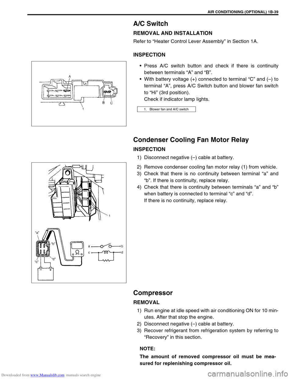
Press A/C switch button and check if there is continuity
between terminals “A” and “B”.
With battery voltage (+) connected to terminal “C” and (–) to
terminal “A”, press A/C Switch button and blower fan switch
to “Hi” (3rd position).
Check if indicator lamp lights.
Condenser Cooling Fan Motor Relay
INSPECTION
1) Disconnect negative (–) cable at battery.
2) Remove condenser cooling fan motor relay (1) from vehicle.
3) Check that there is no continuity between terminal “a” and
“b”. If there is continuity, replace relay.
4) Check that there is continuity between terminals “a” and “b”
when battery is connected to terminal “c” and “d”.
If there is no continuity, replace relay.
Compressor
REMOVAL
1) Run engine at idle speed with air conditioning ON for 10 min-
utes. After that stop the engine.
2) Disconnect negative (–) cable at battery.
3) Recover refrigerant from refrigeration system by referring to
“Recovery” in this section.
1. Blower fan and A/C switch
NOTE:
The amount of removed compressor oil must be mea-
sured for replenishing compressor oil.
Page 177 of 687

Downloaded from www.Manualslib.com manuals search engine 3D-4 FRONT SUSPENSION
SYSTEM CIRCUIT
1. 4WD controller 4. 4WD indicator lamp 7. Blower fan switch 10. Vacuum switch 13. IG fuse
2. VSV1 5. ECM 8. A/C switch (if equipped) 11. Main fuse 14. A/C controller (if equipped)
3. VSV2 6. Blower fan motor 9. 4WD switch 12. IG switch 15. Coupler of 4WD controller
Page 318 of 687

Downloaded from www.Manualslib.com manuals search engine ANTILOCK BRAKE SYSTEM (ABS) 5E-1
6F1
6F2
6G
6H
6K
7A
7A1
7B1
7C1
7D
7E
7F
8E
5E
9
10
10A
10B
10
10A
10B
SECTION 5E
ANTILOCK BRAKE SYSTEM (ABS)
CONTENTS
General Description ....................................... 5E-2
System Schematic ....................................... 5E-3
ABS Component Parts Location .................. 5E-4
ABS Control Module ..................................... 5E-5
Self-diagnosis function ............................. 5E-5
Fail-safe function ...................................... 5E-5
Diagnosis ........................................................ 5E-6
Precaution in Diagnosing Troubles .............. 5E-6
ABS Diagnostic Flow Table .......................... 5E-6
“ABS” Warning Lamp Check ........................ 5E-9
Diagnostic Trouble Code (DTC) Check ........ 5E-9
DTC Check (Using SUZUKI Scan Tool) ..... 5E-10
Diagnostic Trouble Code (DTC)
Clearance ................................................... 5E-10
Diagnostic Trouble Code (DTC) Table ....... 5E-11
System Circuit ............................................ 5E-12
Table – A “ABS” Warning Lamp Circuit
Check – Lamp Does Not Come “ON”
at Ignition Switch ON .................................. 5E-14
Table – B “ABS” Warning Lamp Circuit
Check – Lamp Comes “ON” Steady ........... 5E-15
Table – C “ABS” Warning Lamp Circuit
Check – Lamp Flashes Continuously
While Ignition Switch is ON ........................ 5E-16
Table – D Code (DTC) is Not Outputted
Even With Diag. Switch Terminal
Connected to Ground. ................................ 5E-17
DTC C1015 (DTC 15) – G Sensor
Circuit ......................................................... 5E-18
DTC C1016 (DTC 16) – Stop Lamp
Circuit ......................................................... 5E-20
DTC C1021 (DTC 21), DTC C1022
(DTC 22) – Right Front Wheel Speed
Sensor Circuit ............................................. 5E-21
DTC C1025 (DTC 25), DTC C1026
(DTC 26) – Left Front Wheel Speed
Sensor Circuit ............................................. 5E-21DTC C1031 (DTC 31), DTC C1032
(DTC 32) – Right Rear Wheel Speed
Sensor Circuit ............................................ 5E-21
DTC C1035 (DTC 35), DTC C1036
(DTC 36) – Left Rear Wheel Speed
Sensor Circuit ............................................ 5E-21
DTC C1041 (DTC 41), DTC C1042
(DTC 42) – Right Front Solenoid Circuit .... 5E-24
DTC C1045 (DTC 45), DTC C1046
(DTC 46) – Left Front Solenoid Circuit....... 5E-24
DTC C1055 (DTC 55), DTC C1056
(DTC 56) – Rear Solenoid Circuit .............. 5E-24
DTC C1057 (DTC 57) – Power Source
Circuit ......................................................... 5E-25
DTC C1061 (DTC 61) – ABS Pump
Motor Circuit............................................... 5E-26
DTC C1063 (DTC 63) – ABS Fail Safe
Circuit ......................................................... 5E-27
DTC C1071 (DTC 71) – ABS Control
Module ....................................................... 5E-28
On-Vehicle Service ...................................... 5E-29
Precaution .................................................. 5E-29
ABS Hydraulic Unit Operation Check ........ 5E-29
ABS Hydraulic Unit / Control Module
Assembly ................................................... 5E-30
Front Wheel Speed Sensor........................ 5E-32
Front Wheel Sensor Ring........................... 5E-35
Rear Wheel Speed Sensor ........................ 5E-36
Rear Wheel Sensor Ring ........................... 5E-38
G Sensor .................................................... 5E-39
Tightening Torque Specification ................ 5E-40
Special Tool .................................................. 5E-40 NOTE:
All brake fasteners are important attaching parts in that they could affect the performance of vital
parts and systems, and/or could result in major repair expense. They must be replaced with one of
same part number or with an equivalent part if replacement part of lesser quality or substitute design.
Torque values must be used as specified during reassembly to assure proper retention of all parts.
There is to be no welding as it may result in extensive damage and weakening of the metal.
Page 319 of 687

Downloaded from www.Manualslib.com manuals search engine 5E-2 ANTILOCK BRAKE SYSTEM (ABS)
General Description
The ABS (Antilock Brake System) is a system to prevent each wheel to lock during hard braking or braking on a
slippery road by controlling the fluid pressure from master cylinder to each brake (either brake caliper or wheel
cylinder).
The ABS of this vehicle monitors all four wheels (four sensors) and controls all four wheels when the system is
active.
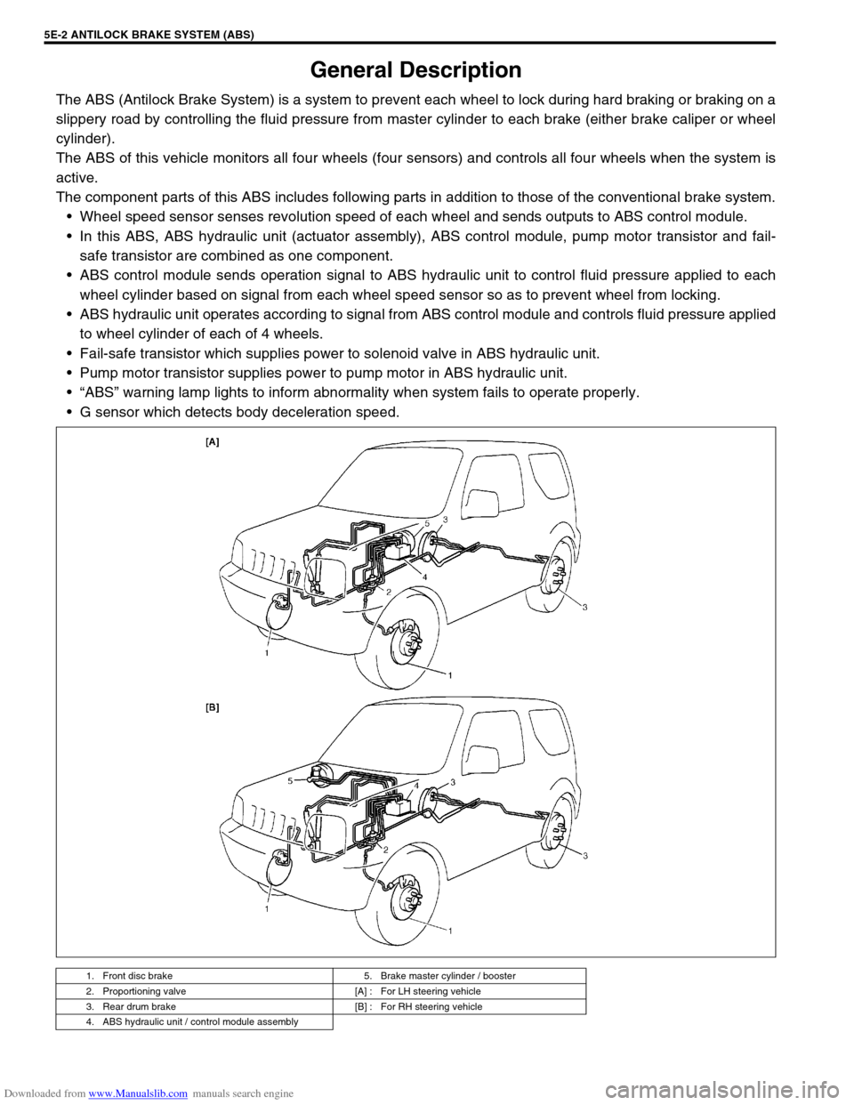
The component parts of this ABS includes following parts in addition to those of the conventional brake system.
Wheel speed sensor senses revolution speed of each wheel and sends outputs to ABS control module.
In this ABS, ABS hydraulic unit (actuator assembly), ABS control module, pump motor transistor and fail-
safe transistor are combined as one component.
ABS control module sends operation signal to ABS hydraulic unit to control fluid pressure applied to each
wheel cylinder based on signal from each wheel speed sensor so as to prevent wheel from locking.
ABS hydraulic unit operates according to signal from ABS control module and controls fluid pressure applied
to wheel cylinder of each of 4 wheels.
Fail-safe transistor which supplies power to solenoid valve in ABS hydraulic unit.
Pump motor transistor supplies power to pump motor in ABS hydraulic unit.
“ABS” warning lamp lights to inform abnormality when system fails to operate properly.
G sensor which detects body deceleration speed.
1. Front disc brake 5. Brake master cylinder / booster
2. Proportioning valve [A] : For LH steering vehicle
3. Rear drum brake [B] : For RH steering vehicle
4. ABS hydraulic unit / control module assembly