2005 SUZUKI JIMNY generator
[x] Cancel search: generatorPage 26 of 687

Downloaded from www.Manualslib.com manuals search engine GENERAL INFORMATION 0A-21
Abbreviations May Be Used In This Manual
Abbreviations
AABC
ATDC
API
ATF
ALR
AC
A/T
A/C
ABDC
A/F
A-ELRAnti-lock Brake System
After Top Dead Center
American Petroleum Institute
Automatic Transmission Fluid
Automatic Locking Retractor
Alternating Current
Automatic Transmission
Air Conditioning
After Bottom Dead Center
Air Fuel Mixture Ratio
Automatic-Emergency
Locking RetractorEEBCM
ECM
ECT Sensor
EGR
EGRT Sensor
EFE Heater
ELR
EPS
EVAP
EVAP CanisterElectronic Brake Control Module,
ABS Control Module
Engine Control Module
Engine Coolant Temperature
Sensor (Water Temp. Sensor,
WTS)
Exhaust Gas Recirculation
EGR Temperature Sensor
(Recirculated Exhaust Gas Temp.
Sensor, REGTS)
Early Fuel Evaporation
Heater (Positive Temperature
Coefficient, PTC Heater)
Emergency Locking Retractor
Electronic Power Steering
Evaporative Emission
Evaporative Emission Canister
(Charcoal Canister) BB+
BTDC
BBDCBattery Positive Voltage
Before Top Dead Center
Before Bottom Dead Center
CCKT
CMP Sensor
CO
CPP Switch
CPU
CRSCircuit
Camshaft Position Sensor
(Crank Angle Sensor, CAS)
Carbon Monoxide
Clutch Pedal Position Switch
(Clutch Switch, Clutch Start
Switch)
Central Processing Unit
Child Restraint SystemF 4WD 4 Wheel Drive
GGEN
GNDGenerator
Ground
HHC
HO2SHydrocarbons
Heated Oxygen Sensor
DDC
DLC
DOHC
DOJ
DRL
DTCDirect Current
Data Link Connector
(Assembly Line Diag. Link, ALDL,
Serial Data Link, SDL)
Double Over Head Camshaft
Double Offset Joint
Daytime Running Light
Diagnostic Trouble Code
(Diagnostic Code)IIAC Valve
IAT Sensor
ICM
IG
ISC ActuatorIdle Air Control Valve (Idle Speed
Control Solenoid Valve, ISC
Solenoid Valve)
Intake Air Temperature Sensor
(Air temperature Sensor, ATS)
Immobilizer Control Module
Ignition
Idle Speed Control Actuator
(Motor)
Page 36 of 687

Downloaded from www.Manualslib.com manuals search engine MAINTENANCE AND LUBRICATION 0B-5
Maintenance Service
Engine
Drive Belt
WATER PUMP AND GENERATOR DRIVE BELT INSPEC-
TION
1) Disconnect negative cable at battery.
2) Inspect belt for cracks, cuts, deformation, wear and cleanli-
ness. If any defect exists, replace.
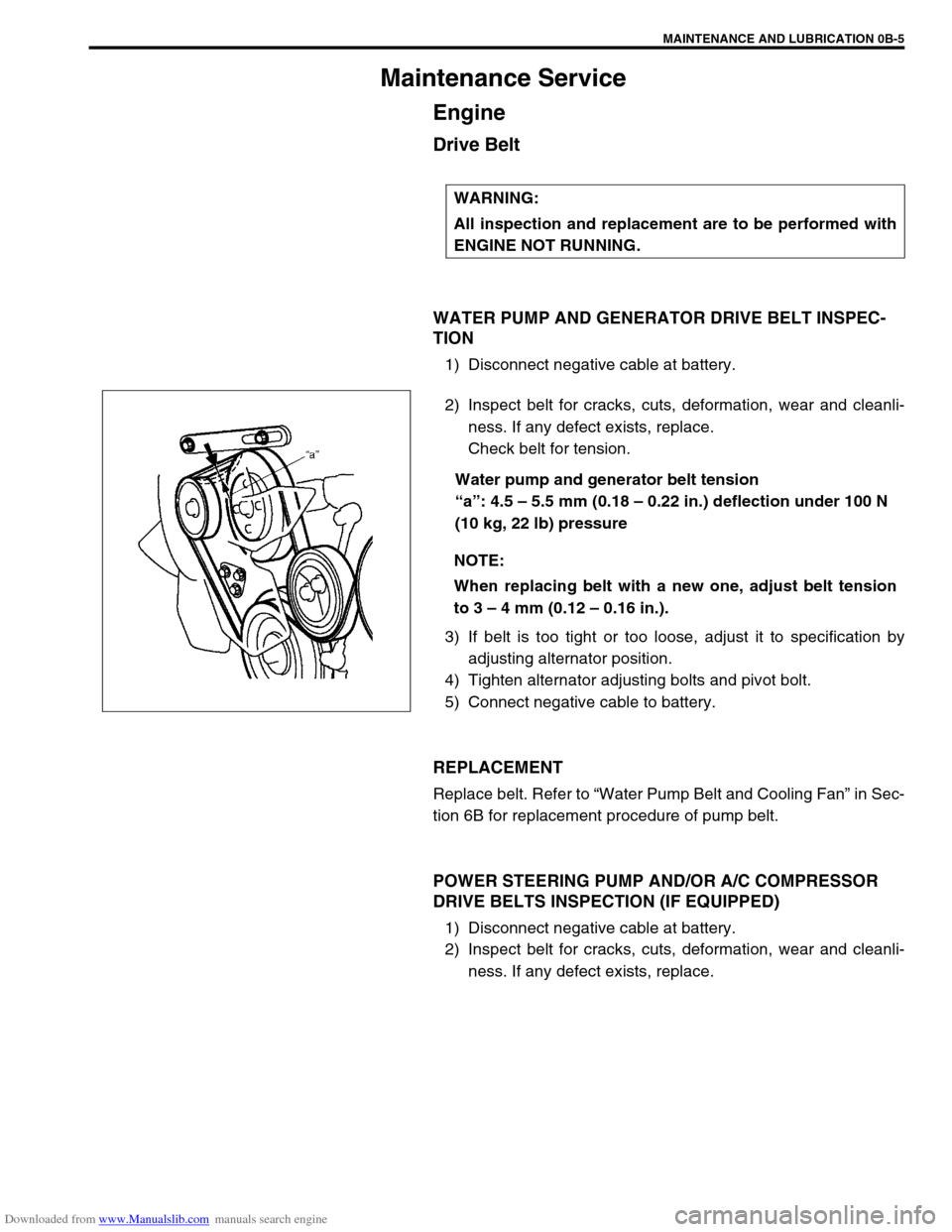
Check belt for tension.
Water pump and generator belt tension
“a”: 4.5 – 5.5 mm (0.18 – 0.22 in.) deflection under 100 N
(10 kg, 22 lb) pressure
3) If belt is too tight or too loose, adjust it to specification by
adjusting alternator position.
4) Tighten alternator adjusting bolts and pivot bolt.
5) Connect negative cable to battery.
REPLACEMENT
Replace belt. Refer to “Water Pump Belt and Cooling Fan” in Sec-
tion 6B for replacement procedure of pump belt.
POWER STEERING PUMP AND/OR A/C COMPRESSOR
DRIVE BELTS INSPECTION (IF EQUIPPED)
1) Disconnect negative cable at battery.
2) Inspect belt for cracks, cuts, deformation, wear and cleanli-
ness. If any defect exists, replace. WARNING:
All inspection and replacement are to be performed with
ENGINE NOT RUNNING.
NOTE:
When replacing belt with a new one, adjust belt tension
to 3 – 4 mm (0.12 – 0.16 in.).
Page 77 of 687
![SUZUKI JIMNY 2005 3.G Service Workshop Manual Downloaded from www.Manualslib.com manuals search engine 1B-16 AIR CONDITIONING (OPTIONAL)
Electronical Diagnosis
Wiring Diagram
[A]: 4WD model 4. Dual pressure switch 9. Thermal switch 14. Circuit fu SUZUKI JIMNY 2005 3.G Service Workshop Manual Downloaded from www.Manualslib.com manuals search engine 1B-16 AIR CONDITIONING (OPTIONAL)
Electronical Diagnosis
Wiring Diagram
[A]: 4WD model 4. Dual pressure switch 9. Thermal switch 14. Circuit fu](/manual-img/20/7588/w960_7588-76.png)
Downloaded from www.Manualslib.com manuals search engine 1B-16 AIR CONDITIONING (OPTIONAL)
Electronical Diagnosis
Wiring Diagram
[A]: 4WD model 4. Dual pressure switch 9. Thermal switch 14. Circuit fuse box
[B]: 2WD model 5. 4WD controller 10. Ignition switch 15. Main fuse box
1. Blower fan motor 6. Condenser cooling fan motor relay 11. A/C evaporator thermistor 16. Generator
2. Blower fan motor resistor 7. Condenser cooling fan motor 12. ECT sensor 17. ECM
3. Blower fan motor switch and A/C switch 8. Compressor 13. Lighting switch
Page 509 of 687

Downloaded from www.Manualslib.com manuals search engine 6A1-28 ENGINE MECHANICAL (M13 ENGINE)
Timing Chain Cover
REMOVAL
1) Disconnect negative cable at battery.
2) Remove A/C compressor and/or P/S pump belt (if
equipped).
3) Remove generator belt.
4) Drain engine oil.
[A] : Sealant application
amount3. Oil seal
: Apply engine oil to oil seal lip.8. Cylinder head cover
: Apply sealant 99000-31150 to the sealing
point for timing chain cover mating surface
and cylinder head gasket sealing point.
Refer to “Cylinder Head Cover Installation”.
“a” : 3 mm (0.12 in.) 4. Timing chain cover Tightening torque
: Apply sealant 99000-31140 to the mating surface
of cylinder and cylinder head.
: Apply sealant 99000-31150 to the mating surface
of timing chain cover referring to the figure of Step
1) in INSTALLATION.
“b” : 2 mm (0.08 in.) 5. Pin Do not reuse.
1. Crankshaft pulley bolt 6. Cylinder head cover gasket
2. Crankshaft pulley 7. Timing chain cover mounting bolts
Page 513 of 687

Downloaded from www.Manualslib.com manuals search engine 6A1-32 ENGINE MECHANICAL (M13 ENGINE)
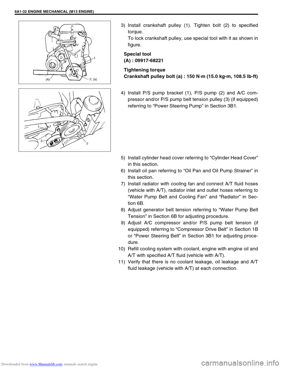
3) Install crankshaft pulley (1). Tighten bolt (2) to specified
torque.
To lock crankshaft pulley, use special tool with it as shown in
figure.
Special tool
(A) : 09917-68221
Tightening torque
Crankshaft pulley bolt (a) : 150 N·m (15.0 kg-m, 108.5 lb-ft)
4) Install P/S pump bracket (1), P/S pump (2) and A/C com-
pressor and/or P/S pump belt tension pulley (3) (if equipped)
referring to “Power Steering Pump” in Section 3B1.
5) Install cylinder head cover referring to “Cylinder Head Cover”
in this section.
6) Install oil pan referring to “Oil Pan and Oil Pump Strainer” in
this section.
7) Install radiator with cooling fan and connect A/T fluid hoses
(vehicle with A/T), radiator inlet and outlet hoses referring to
“Water Pump Belt and Cooling Fan” and “Radiator” in Sec-
tion 6B.
8) Adjust generator belt tension referring to “Water Pump Belt
Tension” in Section 6B for adjusting procedure.
9) Adjust A/C compressor and/or P/S pump belt tension (if
equipped) referring to “Compressor Drive Belt” in Section 1B
or “Power Steering Belt” in Section 3B1 for adjusting proce-
dure.
10) Refill cooling system with coolant, engine with engine oil and
A/T with specified A/T fluid (vehicle with A/T).
11) Verify that there is no coolant leakage, oil leakage and A/T
fluid leakage (vehicle with A/T) at each connection.
Page 528 of 687

Downloaded from www.Manualslib.com manuals search engine ENGINE MECHANICAL (M13 ENGINE) 6A1-47
5) After applying engine oil to housing bolts, tighten them tem-
porarily first. Then tighten them by the following numerical
order in figure. Tighten a little at a time and evenly among
bolts and repeat tightening sequence two or three times
before they are tightened to specified torque.
Tightening torque
Camshaft housing bolts (a) : 11 N·m (1.1 kg-m, 8.0 lb-ft)
6) Install timing chain with crankshaft sprocket referring to
“Timing Chain and Chain Tensioner” in this section.
7) Install timing chain cover referring to “Timing Chain Cover” in
this section.
8) Check valve lashes referring to “Valve Lash” in this section.
9) Install cylinder head cover and oil pan referring to “Cylinder
Head Cover” and “Oil Pan and Oil Pump Strainer” in this sec-
tion.
10) Install radiator with cooling fan and connect A/T fluid hoses
(vehicle with A/T), radiator inlet and outlet hoses referring to
“Water Pump Belt and Cooling Fan” and “Radiator” in Sec-
tion 6B.
11) Adjust generator belt tension referring to “Water Pump Belt
Tension” in Section 6B.
12) Adjust A/C compressor and/or P/S pump belt tension (if
equipped) referring to “Compressor Drive Belt” in Section 1B
or “Power Steering Belt” in Section 3B1.
13) Refill cooling system with coolant, engine with engine oil and
A/T with specified A/T fluid (vehicle with A/T).
14) Verify that there is no coolant leakage, oil leakage and A/T
fluid leakage (vehicle with A/T) at each connection.
Page 542 of 687

Downloaded from www.Manualslib.com manuals search engine ENGINE MECHANICAL (M13 ENGINE) 6A1-61
6) Install exhaust manifold stiffener and exhaust pipe referring
to “Exhaust Manifold” in this section.
7) Install camshafts, timing chain and chain cover referring to
“Camshaft, Tappet and Shim”, “Timing Chain and Chain
Tensioner” and “Timing Chain Cover” in this section.
8) Install cylinder head cover and oil pan referring to “Cylinder
Head Cover” and “Oil Pan and Oil Pump Strainer” in this sec-
tion.
9) Install intake manifold stiffener and connect each hoses and
electric lead wires securely.
10) Install air cleaner outlet hoses.
11) Install radiator with cooling fan and connect A/T fluid hoses
(vehicle with A/T), radiator inlet and outlet hoses referring to
“Water Pump Belt and Cooling Fan” and “Radiator” in Sec-
tion 6B.
12) Adjust generator belt tension referring to “Water Pump Belt
Tension” in Section 6B.
13) Adjust A/C compressor and/or P/S pump belt tension (if
equipped) referring to “Compressor Drive Belt” in Section 1B
or “Power Steering Belt” in Section 3B1.
14) Adjust accelerator cable play referring to “Accelerator Cable
Adjustment” in Section 6E.
15) Check to ensure that all removed parts are back in place.
Reinstall any necessary parts which have not been rein-
stalled.
16) Refill cooling system with coolant, engine with engine oil and
A/T with specified A/T fluid (vehicle with A/T).
17) Connect negative cable at battery.
18) Verify that there is no fuel leakage, coolant leakage, oil leak-
age, A/T fluid leakage (vehicle with A/T) and exhaust gas
leakage at each connection.
Page 552 of 687

Downloaded from www.Manualslib.com manuals search engine ENGINE MECHANICAL (M13 ENGINE) 6A1-71
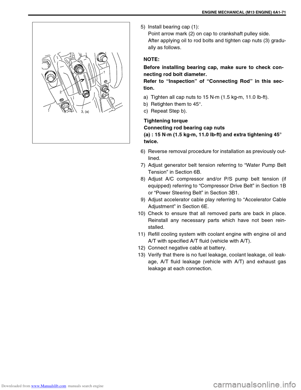
5) Install bearing cap (1):
Point arrow mark (2) on cap to crankshaft pulley side.
After applying oil to rod bolts and tighten cap nuts (3) gradu-
ally as follows.
a) Tighten all cap nuts to 15 N·m (1.5 kg-m, 11.0 lb-ft).
b) Retighten them to 45°.
c) Repeat Step b).
Tightening torque
Connecting rod bearing cap nuts
(a) : 15 N·m (1.5 kg-m, 11.0 lb-ft) and extra tightening 45°
twice.
6) Reverse removal procedure for installation as previously out-
lined.
7) Adjust generator belt tension referring to “Water Pump Belt
Tension” in Section 6B.
8) Adjust A/C compressor and/or P/S pump belt tension (if
equipped) referring to “Compressor Drive Belt” in Section 1B
or “Power Steering Belt” in Section 3B1.
9) Adjust accelerator cable play referring to “Accelerator Cable
Adjustment” in Section 6E.
10) Check to ensure that all removed parts are back in place.
Reinstall any necessary parts which have not been rein-
stalled.
11) Refill cooling system with coolant engine with engine oil and
A/T with specified A/T fluid (vehicle with A/T).
12) Connect negative cable at battery.
13) Verify that there is no fuel leakage, coolant leakage, oil leak-
age, A/T fluid leakage (vehicle with A/T) and exhaust gas
leakage at each connection. NOTE:
Before installing bearing cap, make sure to check con-
necting rod bolt diameter.
Refer to “Inspection” of “Connecting Rod” in this sec-
tion.