2005 SUZUKI JIMNY Eps
[x] Cancel search: EpsPage 533 of 687
Downloaded from www.Manualslib.com manuals search engine 6A1-52 ENGINE MECHANICAL (M13 ENGINE)
DISASSEMBLY
1) For ease in servicing cylinder head, remove intake manifold,
injectors and exhaust manifold from cylinder head.
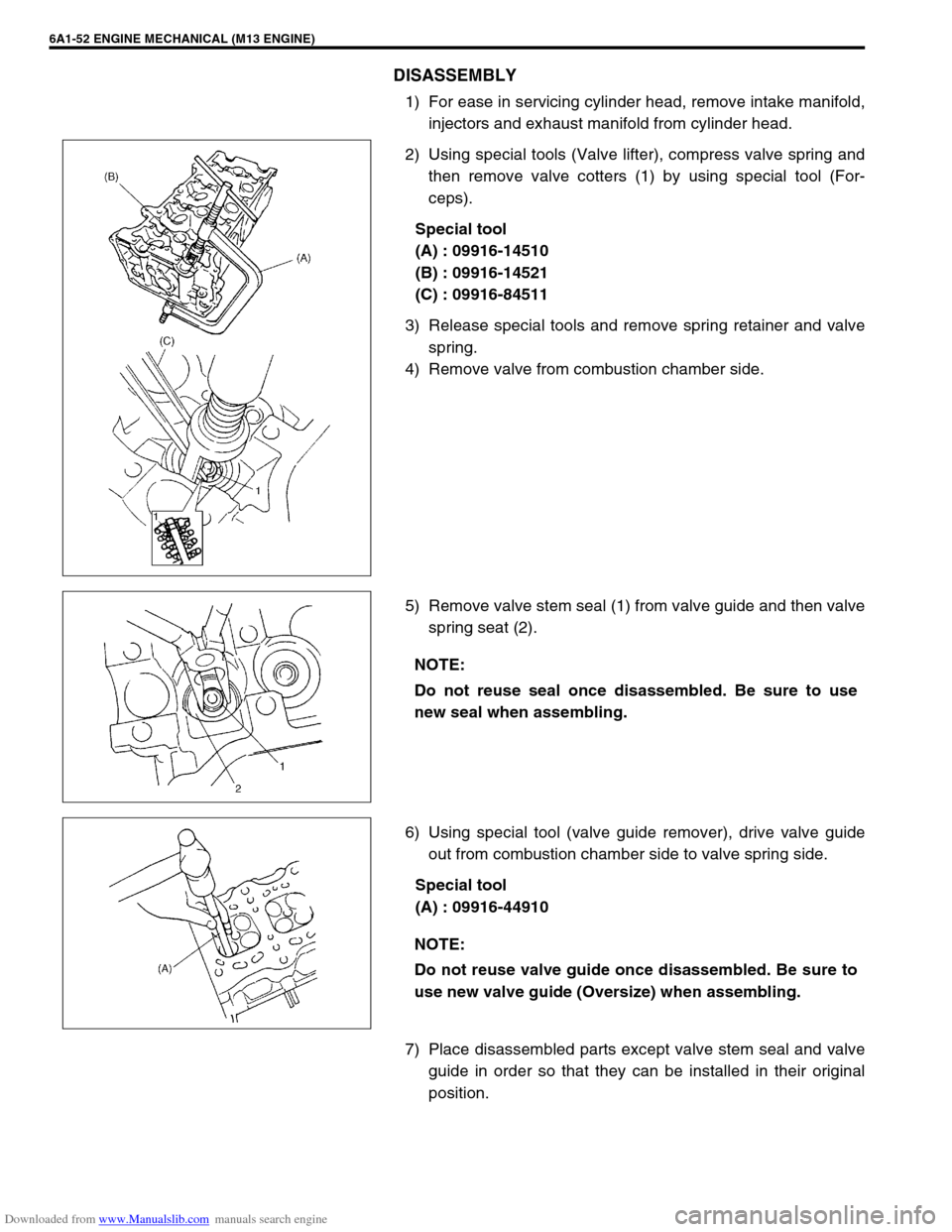
2) Using special tools (Valve lifter), compress valve spring and
then remove valve cotters (1) by using special tool (For-
ceps).
Special tool
(A) : 09916-14510
(B) : 09916-14521
(C) : 09916-84511
3) Release special tools and remove spring retainer and valve
spring.
4) Remove valve from combustion chamber side.
5) Remove valve stem seal (1) from valve guide and then valve
spring seat (2).
6) Using special tool (valve guide remover), drive valve guide
out from combustion chamber side to valve spring side.
Special tool
(A) : 09916-44910
7) Place disassembled parts except valve stem seal and valve
guide in order so that they can be installed in their original
position.
NOTE:
Do not reuse seal once disassembled. Be sure to use
new seal when assembling.
NOTE:
Do not reuse valve guide once disassembled. Be sure to
use new valve guide (Oversize) when assembling.
Page 536 of 687
Downloaded from www.Manualslib.com manuals search engine ENGINE MECHANICAL (M13 ENGINE) 6A1-55
Valve seat repair:
A valve seat not producing a uniform contact with its valve or
showing width of seating contact that is out of specified
range must be repaired by regrinding or by cutting and
regrinding and finished by lapping.
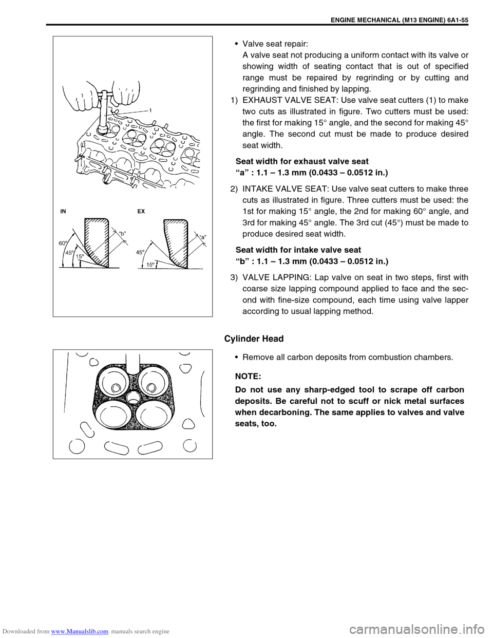
1) EXHAUST VALVE SEAT: Use valve seat cutters (1) to make
two cuts as illustrated in figure. Two cutters must be used:
the first for making 15° angle, and the second for making 45°
angle. The second cut must be made to produce desired
seat width.
Seat width for exhaust valve seat
“a” : 1.1 – 1.3 mm (0.0433 – 0.0512 in.)
2) INTAKE VALVE SEAT: Use valve seat cutters to make three
cuts as illustrated in figure. Three cutters must be used: the
1st for making 15° angle, the 2nd for making 60° angle, and
3rd for making 45° angle. The 3rd cut (45°) must be made to
produce desired seat width.
Seat width for intake valve seat
“b” : 1.1 – 1.3 mm (0.0433 – 0.0512 in.)
3) VALVE LAPPING: Lap valve on seat in two steps, first with
coarse size lapping compound applied to face and the sec-
ond with fine-size compound, each time using valve lapper
according to usual lapping method.
Cylinder Head
Remove all carbon deposits from combustion chambers.
NOTE:
Do not use any sharp-edged tool to scrape off carbon
deposits. Be careful not to scuff or nick metal surfaces
when decarboning. The same applies to valves and valve
seats, too.
Page 555 of 687
Downloaded from www.Manualslib.com manuals search engine 6A1-74 ENGINE MECHANICAL (M13 ENGINE)
a) For right hand steering vehicle:
With hose connected, detach A/C compressor from its
bracket.
b) For left hand steering vehicle:
i) Recover refrigerant from refrigeration system using recov-
ery and recycling equipment.
ii) Disconnect magnet clutch lead wire.
iii) Remove suction pipe and disconnect discharge pipe from
A/C compressor.
iv) Remove A/C compressor from its bracket.
When servicing above steps, refer to “Compressor” in Section 1B.
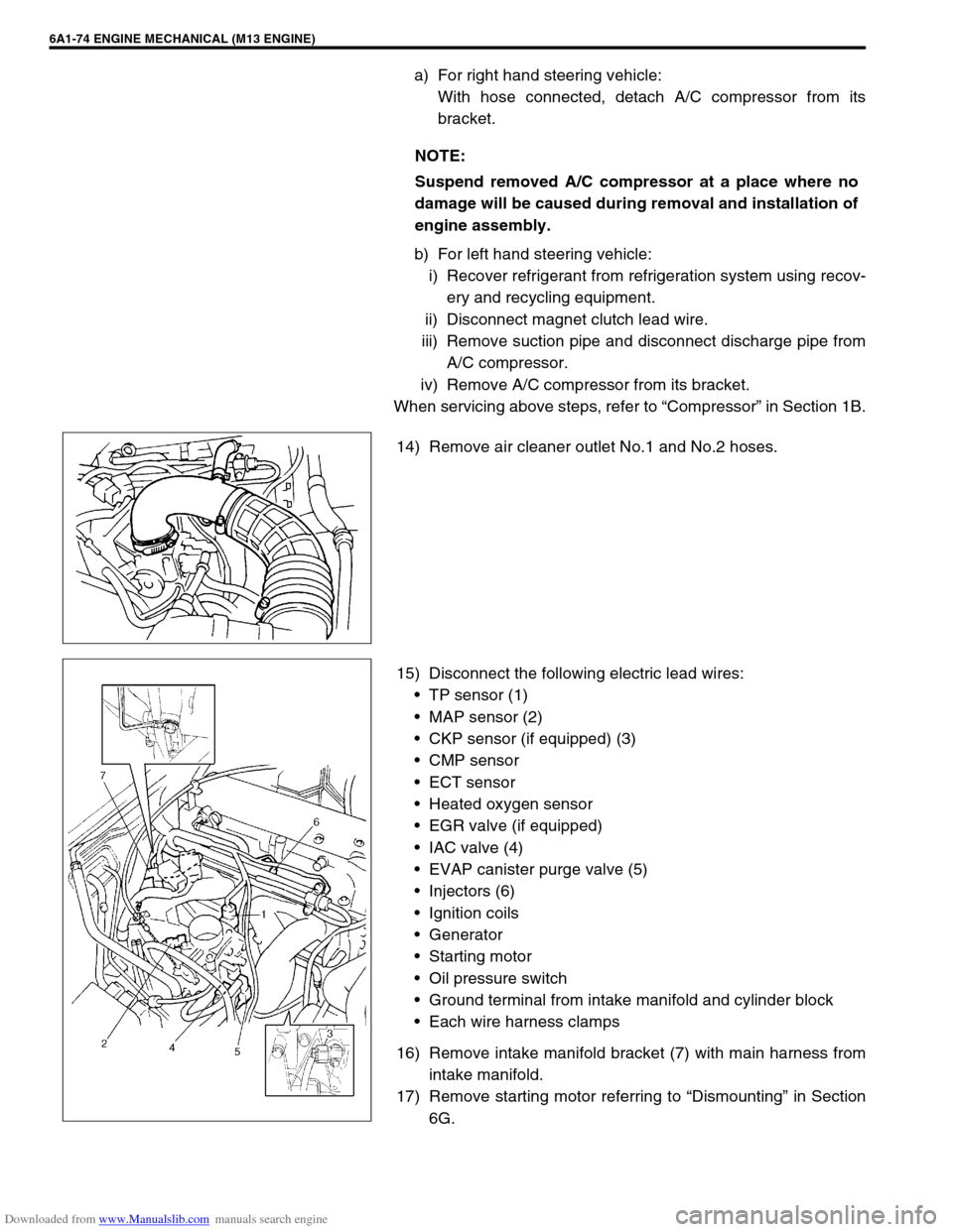
14) Remove air cleaner outlet No.1 and No.2 hoses.
15) Disconnect the following electric lead wires:
TP sensor (1)
MAP sensor (2)
CKP sensor (if equipped) (3)
CMP sensor
ECT sensor
Heated oxygen sensor
EGR valve (if equipped)
IAC valve (4)
EVAP canister purge valve (5)
Injectors (6)
Ignition coils
Generator
Starting motor
Oil pressure switch
Ground terminal from intake manifold and cylinder block
Each wire harness clamps
16) Remove intake manifold bracket (7) with main harness from
intake manifold.
17) Remove starting motor referring to “Dismounting” in Section
6G. NOTE:
Suspend removed A/C compressor at a place where no
damage will be caused during removal and installation of
engine assembly.
Page 576 of 687

Downloaded from www.Manualslib.com manuals search engine ENGINE MECHANICAL (M13 ENGINE) 6A1-95
09915-67310 09915-77310 09915-78211 09916-14510
Vacuum gauge Oil pressure gauge Oil pressure gauge
attachmentValve lifter
09916-14521 09916-34542 09916-34550 09916-37320
Valve lifter attachment Reamer handle Reamer (5.5 mm) Reamer (10.5 mm)
09916-44910 09916-56011 09916-58210 09916-67020
Valve guide remover Valve guide installer
attachmentValve guide installer han-
dleTappet holder
09916-77310 09916-84511 09917-68221 09917-98221
Piston ring compressor Forceps Camshaft lock holder Valve stem seal installer
Page 585 of 687
Downloaded from www.Manualslib.com manuals search engine 6B-8 ENGINE COOLING
5) Tighten hose clamps and inspect all hoses.
Replace hoses whenever cracked, swollen or otherwise
deteriorated.
6) Clean frontal area of radiator core.
Cooling System Flush and Refill
1) Remove radiator cap when engine is cool:
Turn cap slowly to the left until it reaches a “stop” (Do not
press down while turning it).
Wait until pressure is relieved (indicated by a hissing sound)
then press down on cap and continue to turn it to the left.
2) With radiator cap removed, run engine until upper radiator
hose is hot (this shows that thermostat is open and coolant is
flowing through system).
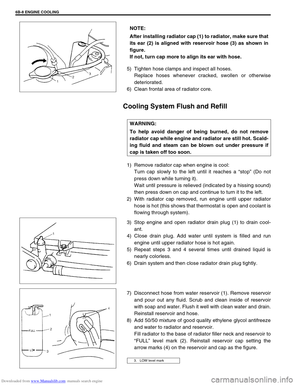
3) Stop engine and open radiator drain plug (1) to drain cool-
ant.
4) Close drain plug. Add water until system is filled and run
engine until upper radiator hose is hot again.
5) Repeat steps 3 and 4 several times until drained liquid is
nearly colorless.
6) Drain system and then close radiator drain plug tightly.
7) Disconnect hose from water reservoir (1). Remove reservoir
and pour out any fluid. Scrub and clean inside of reservoir
with soap and water. Flush it well with clean water and drain.
Reinstall reservoir and hose.
8) Add 50/50 mixture of good quality ethylene glycol antifreeze
and water to radiator and reservoir.
Fill radiator to the base of radiator filler neck and reservoir to
“FULL” level mark (2). Reinstall reservoir cap setting the
arrow marks (4) on the reservoir and cap as the figure. NOTE:
After installing radiator cap (1) to radiator, make sure that
its ear (2) is aligned with reservoir hose (3) as shown in
figure.
If not, turn cap more to align its ear with hose.
WARNING:
To help avoid danger of being burned, do not remove
radiator cap while engine and radiator are still hot. Scald-
ing fluid and steam can be blown out under pressure if
cap is taken off too soon.
3. LOW level mark
Page 611 of 687
Downloaded from www.Manualslib.com manuals search engine 6E-6 ENGINE AND EMISSION CONTROL SYSTEM
Fuel Delivery System
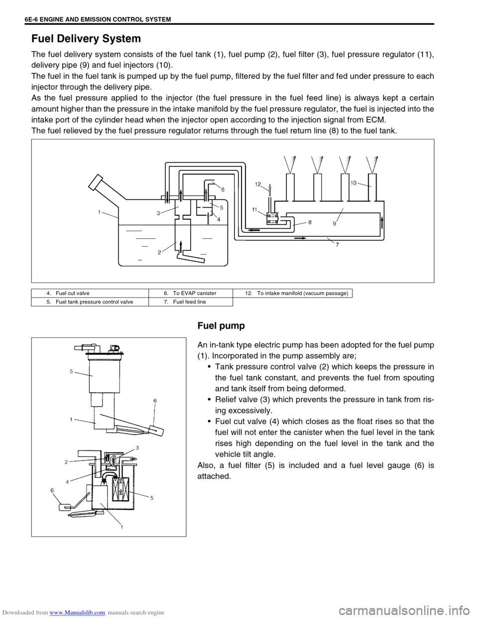
The fuel delivery system consists of the fuel tank (1), fuel pump (2), fuel filter (3), fuel pressure regulator (11),
delivery pipe (9) and fuel injectors (10).
The fuel in the fuel tank is pumped up by the fuel pump, filtered by the fuel filter and fed under pressure to each
injector through the delivery pipe.
As the fuel pressure applied to the injector (the fuel pressure in the fuel feed line) is always kept a certain
amount higher than the pressure in the intake manifold by the fuel pressure regulator, the fuel is injected into the
intake port of the cylinder head when the injector open according to the injection signal from ECM.
The fuel relieved by the fuel pressure regulator returns through the fuel return line (8) to the fuel tank.
Fuel pump
An in-tank type electric pump has been adopted for the fuel pump
(1). Incorporated in the pump assembly are;
Tank pressure control valve (2) which keeps the pressure in
the fuel tank constant, and prevents the fuel from spouting
and tank itself from being deformed.
Relief valve (3) which prevents the pressure in tank from ris-
ing excessively.
Fuel cut valve (4) which closes as the float rises so that the
fuel will not enter the canister when the fuel level in the tank
rises high depending on the fuel level in the tank and the
vehicle tilt angle.
Also, a fuel filter (5) is included and a fuel level gauge (6) is
attached.
4. Fuel cut valve 6. To EVAP canister 12. To intake manifold (vacuum passage)
5. Fuel tank pressure control valve 7. Fuel feed line
Page 645 of 687
Downloaded from www.Manualslib.com manuals search engine 6E-40 ENGINE AND EMISSION CONTROL SYSTEM
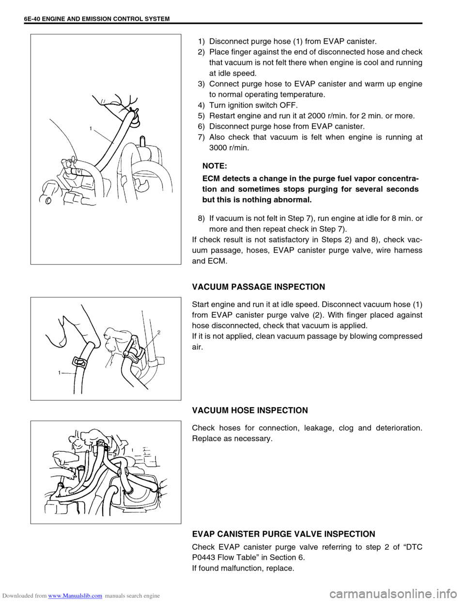
1) Disconnect purge hose (1) from EVAP canister.
2) Place finger against the end of disconnected hose and check
that vacuum is not felt there when engine is cool and running
at idle speed.
3) Connect purge hose to EVAP canister and warm up engine
to normal operating temperature.
4) Turn ignition switch OFF.
5) Restart engine and run it at 2000 r/min. for 2 min. or more.
6) Disconnect purge hose from EVAP canister.
7) Also check that vacuum is felt when engine is running at
3000 r/min.
8) If vacuum is not felt in Step 7), run engine at idle for 8 min. or
more and then repeat check in Step 7).
If check result is not satisfactory in Steps 2) and 8), check vac-
uum passage, hoses, EVAP canister purge valve, wire harness
and ECM.
VACUUM PASSAGE INSPECTION
Start engine and run it at idle speed. Disconnect vacuum hose (1)
from EVAP canister purge valve (2). With finger placed against
hose disconnected, check that vacuum is applied.
If it is not applied, clean vacuum passage by blowing compressed
air.
VACUUM HOSE INSPECTION
Check hoses for connection, leakage, clog and deterioration.
Replace as necessary.
EVAP CANISTER PURGE VALVE INSPECTION
Check EVAP canister purge valve referring to step 2 of “DTC
P0443 Flow Table” in Section 6.
If found malfunction, replace.NOTE:
ECM detects a change in the purge fuel vapor concentra-
tion and sometimes stops purging for several seconds
but this is nothing abnormal.