Page 621 of 687

Downloaded from www.Manualslib.com manuals search engine 6E-16 ENGINE AND EMISSION CONTROL SYSTEM
1) Connect SUZUKI scan tool to DLC with ignition switch OFF,
if it is available.
2) Warm up engine to normal operating temperature.
3) Check engine idle speed and “IAC duty” as follows:
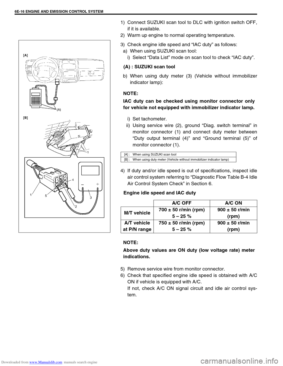
a) When using SUZUKI scan tool:
i) Select “Data List” mode on scan tool to check “IAC duty”.
(A) : SUZUKI scan tool
b) When using duty meter (3) (Vehicle without immobilizer
indicator lamp):
i) Set tachometer.
ii) Using service wire (2), ground “Diag. switch terminal” in
monitor connector (1) and connect duty meter between
“Duty output terminal (4)” and “Ground terminal (5)” of
monitor connector (1).
4) If duty and/or idle speed is out of specifications, inspect idle
air control system referring to “Diagnostic Flow Table B-4 Idle
Air Control System Check” in Section 6.
Engine idle speed and IAC duty
5) Remove service wire from monitor connector.
6) Check that specified engine idle speed is obtained with A/C
ON if vehicle is equipped with A/C.
If not, check A/C ON signal circuit and idle air control sys-
tem. NOTE:
IAC duty can be checked using monitor connector only
for vehicle not equipped with immobilizer indicator lamp.
[A] : When using SUZUKI scan tool
[B] : When using duty meter (Vehicle without immobilizer indicator lamp)
A/C OFF A/C ON
M/T vehicle700 ± 50 r/min (rpm)
5 – 25 %900 ± 50 r/min
(rpm)
A/T vehicle
at P/N range750 ± 50 r/min (rpm)
5 – 25 %900 ± 50 r/min
(rpm)
NOTE:
Above duty values are ON duty (low voltage rate) meter
indications.
Page 622 of 687

Downloaded from www.Manualslib.com manuals search engine ENGINE AND EMISSION CONTROL SYSTEM 6E-17
Idle mixture inspection / adjustment (vehicle without
heated oxygen sensor)
All vehicles not equipped with heated oxygen sensor are shipped
with their CO % factory adjusted as follows.
Engine idle mixture (CO %)
0.5 – 1.5 % at specified idle speed
Idle mixture adjustment should never be changed from the origi-
nal factory setting. However, if during diagnosis, the check indi-
cates idle mixture to be the cause of a driver performance
complaint or emission failure, the idle mixture can be adjusted
using the following procedures.
1) Check idle speed according to “Idle Speed / Idle Air Control
(IAC) Duty Inspection” in this section.
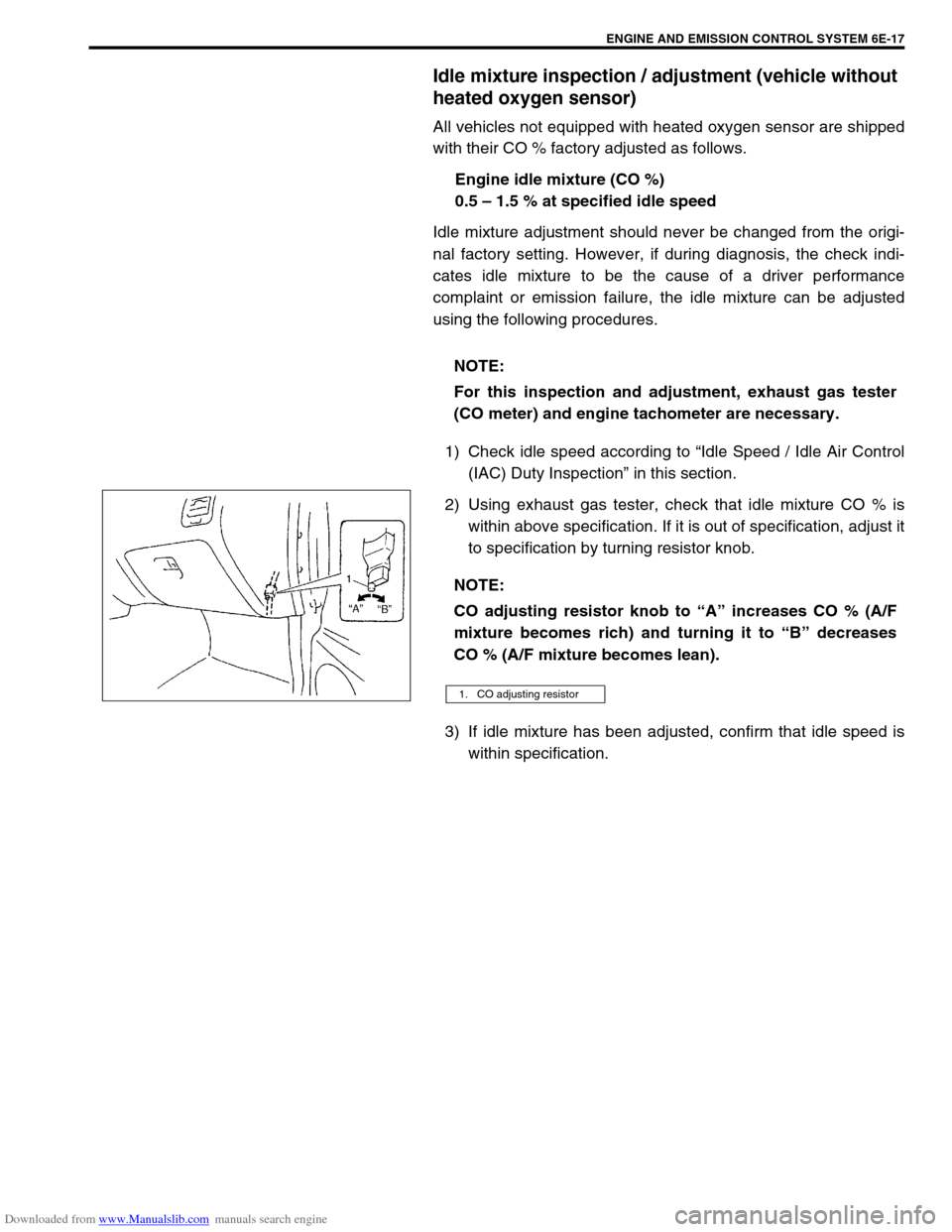
2) Using exhaust gas tester, check that idle mixture CO % is
within above specification. If it is out of specification, adjust it
to specification by turning resistor knob.
3) If idle mixture has been adjusted, confirm that idle speed is
within specification. NOTE:
For this inspection and adjustment, exhaust gas tester
(CO meter) and engine tachometer are necessary.
NOTE:
CO adjusting resistor knob to “A” increases CO % (A/F
mixture becomes rich) and turning it to “B” decreases
CO % (A/F mixture becomes lean).
1. CO adjusting resistor
Page 623 of 687
Downloaded from www.Manualslib.com manuals search engine 6E-18 ENGINE AND EMISSION CONTROL SYSTEM
Air Intake System
Throttle body
ON-VEHICLE INSPECTION
Check that throttle valve lever (1) moves smoothly.
REMOVAL
1) Disconnect negative cable at battery.
2) Drain cooling system.
3) Disconnect accelerator cable (1) from throttle valve lever.
1. Throttle body 4. Gasket 7. TP sensor screws
2. Throttle body gasket 5. Idle air control valve Tightening torque
3. TP sensor 6. IAC valve screws Do not reuse
Page 624 of 687

Downloaded from www.Manualslib.com manuals search engine ENGINE AND EMISSION CONTROL SYSTEM 6E-19
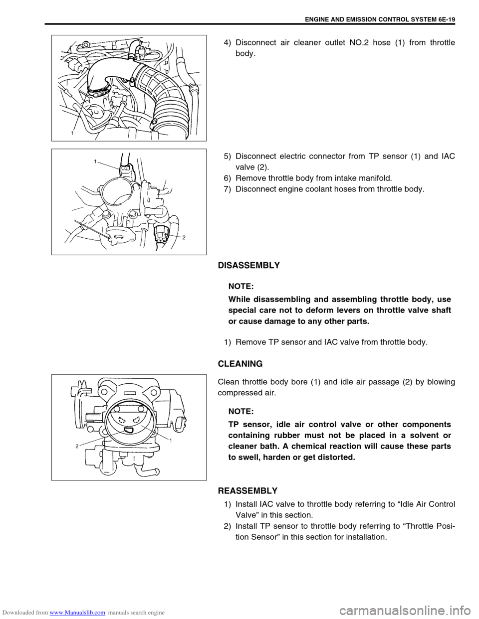
4) Disconnect air cleaner outlet NO.2 hose (1) from throttle
body.
5) Disconnect electric connector from TP sensor (1) and IAC
valve (2).
6) Remove throttle body from intake manifold.
7) Disconnect engine coolant hoses from throttle body.
DISASSEMBLY
1) Remove TP sensor and IAC valve from throttle body.
CLEANING
Clean throttle body bore (1) and idle air passage (2) by blowing
compressed air.
REASSEMBLY
1) Install IAC valve to throttle body referring to “Idle Air Control
Valve” in this section.
2) Install TP sensor to throttle body referring to “Throttle Posi-
tion Sensor” in this section for installation.
NOTE:
While disassembling and assembling throttle body, use
special care not to deform levers on throttle valve shaft
or cause damage to any other parts.
NOTE:
TP sensor, idle air control valve or other components
containing rubber must not be placed in a solvent or
cleaner bath. A chemical reaction will cause these parts
to swell, harden or get distorted.
Page 625 of 687
Downloaded from www.Manualslib.com manuals search engine 6E-20 ENGINE AND EMISSION CONTROL SYSTEM
INSTALLATION
1) Clean mating surfaces and install throttle body gasket to
intake manifold.
Use new gasket.
2) Connect engine coolant hoses.
3) Install throttle body (1) to intake manifold.
4) Connect connectors to TP sensor (2) and IAC valve (3)
securely.
5) Install air cleaner outlet No.2 hose (1) and pipe.
6) Connect accelerator cable and adjust cable play to specifica-
tion.
7) Refill cooling system.
8) Connect negative cable at battery.
Page 626 of 687

Downloaded from www.Manualslib.com manuals search engine ENGINE AND EMISSION CONTROL SYSTEM 6E-21
Idle air control valve (IAC valve)
REMOVAL
1) Remove throttle body from intake manifold referring to
“Throttle Body” in this section for removal.
2) Remove IAC valve from throttle body.
INSPECTION
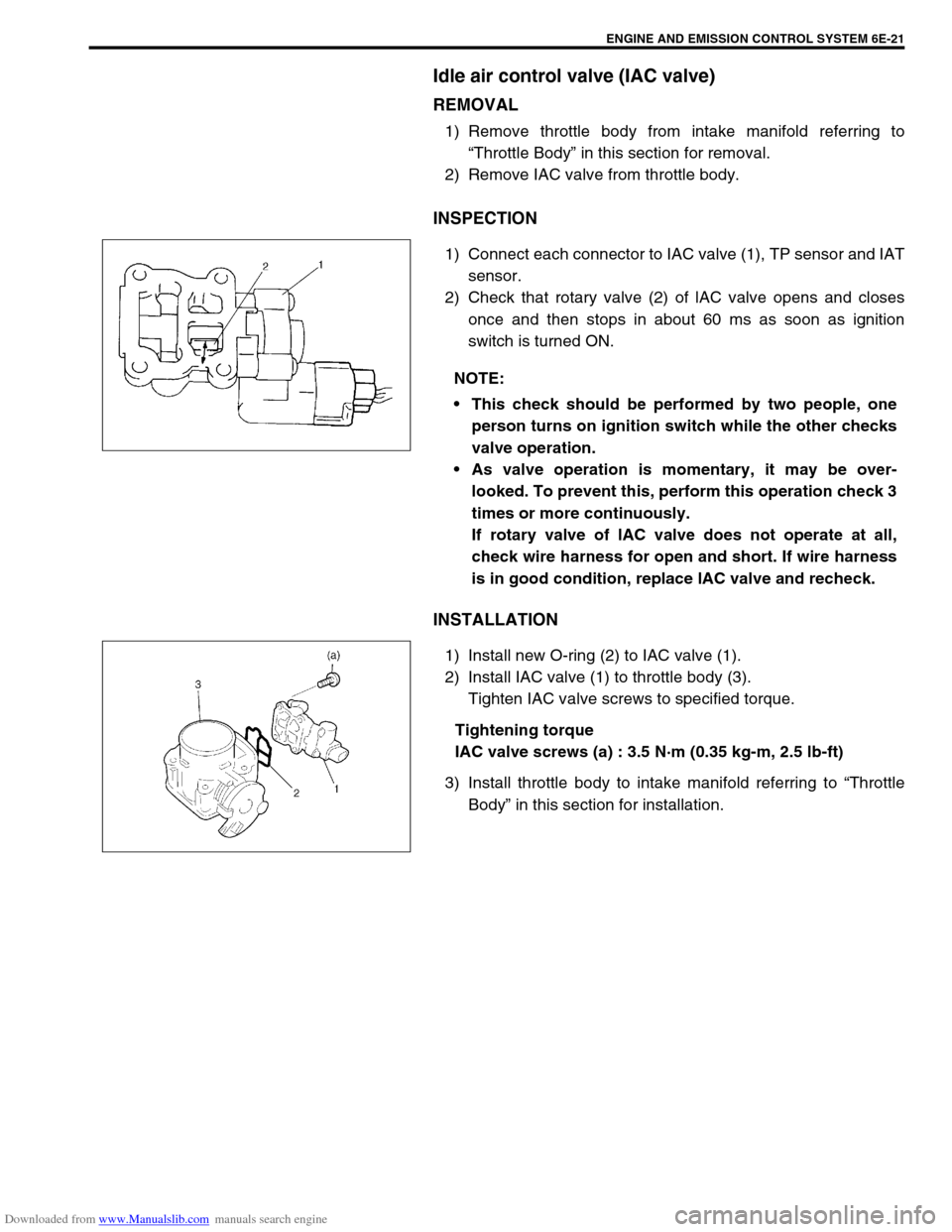
1) Connect each connector to IAC valve (1), TP sensor and IAT
sensor.
2) Check that rotary valve (2) of lAC valve opens and closes
once and then stops in about 60 ms as soon as ignition
switch is turned ON.
INSTALLATION
1) Install new O-ring (2) to IAC valve (1).
2) Install IAC valve (1) to throttle body (3).
Tighten IAC valve screws to specified torque.
Tightening torque
IAC valve screws (a) : 3.5 N·m (0.35 kg-m, 2.5 lb-ft)
3) Install throttle body to intake manifold referring to “Throttle
Body” in this section for installation. NOTE:
This check should be performed by two people, one
person turns on ignition switch while the other checks
valve operation.
As valve operation is momentary, it may be over-
looked. To prevent this, perform this operation check 3
times or more continuously.
If rotary valve of lAC valve does not operate at all,
check wire harness for open and short. If wire harness
is in good condition, replace lAC valve and recheck.
Page 634 of 687
Downloaded from www.Manualslib.com manuals search engine ENGINE AND EMISSION CONTROL SYSTEM 6E-29
Electronic Control System
Engine control module (ECM)
REMOVAL
1) Disconnect battery negative cable at battery.
2) Disable air bag system, refer to “Disabling Air Bag System”
in Section 10B if equipped.
3) Remove glove box.
4) Disconnect ECM (1) and TCM (3) (if equipped) connectors.
5) Loosen 2 nuts (2) and remove ECM and TCM (if equipped).
INSTALLATION
1) Reverse removal procedure noting the following:
Connect connectors to ECM and TCM (if equipped)
securely.
Manifold absolute pressure sensor (MAP sensor)
INSPECTION
Check MAP sensor referring to “MAP Sensor Individual Check” in
DTC P0105 (No.11) Flow Table of Section 6. If malfunction is
found, replace.CAUTION:
As ECM consists of precision parts, be careful not to
expose it to excessive shock.
Page 636 of 687
Downloaded from www.Manualslib.com manuals search engine ENGINE AND EMISSION CONTROL SYSTEM 6E-31
Intake air temperature sensor (IAT sensor)
REMOVAL
1) Disconnect battery negative cable at battery.
2) Disconnect connector from IAT sensor (1).
3) Remove IAT sensor (1) from air cleaner case (2).
INSPECTION
Immerse temperature sensing part of IAT sensor in water (or ice)
and measure resistance between sensor terminals while heating
water gradually.
If measured resistance doesn’t show such characteristic as
shown in left figure, replace IAT sensor.
INSTALLATION
Reverse removal procedure noting the following.
Clean mating surfaces of IAT sensor and air cleaner case.
Connect IAT sensor connector (1) securely.