2005 SUZUKI JIMNY AIR CON
[x] Cancel search: AIR CONPage 644 of 687

Downloaded from www.Manualslib.com manuals search engine ENGINE AND EMISSION CONTROL SYSTEM 6E-39
REMOVAL
1) Disconnect negative cable at battery.
2) Disconnect EGR valve connector.
3) Remove EGR pipe.
4) Remove EGR valve and gasket from cylinder head.
INSPECTION
1) Check resistance between following terminals of EGR valve
(1) in each pair.
If found faulty, replace EGR valve assembly.
EGR valve resistance
2) Remove carbon from EGR valve (1) gas passage.
3) Inspect valve (2), valve seat (3) and rod for fault, cracks,
bend or other damage.
If found faulty, replace EGR valve assembly.
INSTALLATION
Reverse removal procedure noting following.
Clean mating surface of valve and cylinder head.
Use new gaskets.
Evaporative emission (EVAP) control system
EVAP CANISTER PURGE INSPECTION
Terminal Standard resistance
A – B
C – B
F – E
D – E 20 – 24
Ω
ΩΩ Ω
NOTE:
Do not use any sharp-edged tool to remove carbon.
Be careful not to damage or bend EGR valve, valve seat
and rod.
NOTE:
Before inspection, check to make sure that gear shift
lever is in neutral position (with A/T model, selector lever
in “P” range) and that parking brake lever is pulled all the
way up.
Page 645 of 687

Downloaded from www.Manualslib.com manuals search engine 6E-40 ENGINE AND EMISSION CONTROL SYSTEM
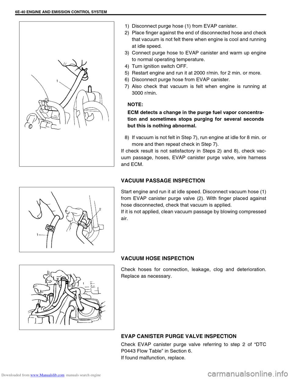
1) Disconnect purge hose (1) from EVAP canister.
2) Place finger against the end of disconnected hose and check
that vacuum is not felt there when engine is cool and running
at idle speed.
3) Connect purge hose to EVAP canister and warm up engine
to normal operating temperature.
4) Turn ignition switch OFF.
5) Restart engine and run it at 2000 r/min. for 2 min. or more.
6) Disconnect purge hose from EVAP canister.
7) Also check that vacuum is felt when engine is running at
3000 r/min.
8) If vacuum is not felt in Step 7), run engine at idle for 8 min. or
more and then repeat check in Step 7).
If check result is not satisfactory in Steps 2) and 8), check vac-
uum passage, hoses, EVAP canister purge valve, wire harness
and ECM.
VACUUM PASSAGE INSPECTION
Start engine and run it at idle speed. Disconnect vacuum hose (1)
from EVAP canister purge valve (2). With finger placed against
hose disconnected, check that vacuum is applied.
If it is not applied, clean vacuum passage by blowing compressed
air.
VACUUM HOSE INSPECTION
Check hoses for connection, leakage, clog and deterioration.
Replace as necessary.
EVAP CANISTER PURGE VALVE INSPECTION
Check EVAP canister purge valve referring to step 2 of “DTC
P0443 Flow Table” in Section 6.
If found malfunction, replace.NOTE:
ECM detects a change in the purge fuel vapor concentra-
tion and sometimes stops purging for several seconds
but this is nothing abnormal.
Page 646 of 687

Downloaded from www.Manualslib.com manuals search engine ENGINE AND EMISSION CONTROL SYSTEM 6E-41
EVAP CANISTER INSPECTION
1) Check outside of EVAP canister visually.
2) Disconnect vacuum hoses from EVAP canister.
3) Check that there should be no restriction of flow through
purge pipe (1) and air pipe (2) when air is blown (4) into tank
pipe (3).
If any faulty condition is found in above inspection replace.
PCV system
PCV HOSE INSPECTION
Check hoses for connection, leakage, clog and deterioration.
Replace as necessary.
PCV VALVE INSPECTION
1) Disconnect PCV valve (1) from cylinder head cover and
install plug to head cover hole.
2) Run engine at idle.
3) Place your finger over end of PCV valve (1) to check for vac-
uum. If there is no vacuum, check for clogged valve.
Replace as necessary. WARNING:
DO NOT SUCK nozzles on EVAP canister. Fuel vapor
inside EVAP canister is harmful.
NOTE:
Be sure to check that there is no obstruction in PCV
valve or its hoses before checking IAC duty, for
obstructed PCV valve or hose hampers its accurate
adjustment.
Page 650 of 687

Downloaded from www.Manualslib.com manuals search engine IGNITION SYSTEM (ELECTRONIC IGNITION SYSTEM) 6F-1
6G
6F2
6G
6H
7D
7E
7F
7A1
7A1
7D
7E
7F
8A
8B
8C
8D
8E
6K
6F
7A
10
10A
10B
SECTION 6F
IGNITION SYSTEM
(ELECTRONIC IGNITION SYSTEM)
CONTENTS
General Description ........................................ 6F-2
Diagnosis ......................................................... 6F-3
On-Vehicle Service.......................................... 6F-5
Ignition Spark Test ........................................ 6F-5
High-tension Cords ....................................... 6F-5
Spark Plugs ................................................... 6F-6Ignition Coil Assembly (Including Ignitor) ...... 6F-7
Crankshaft Position Sensor (CKP Sensor) ... 6F-8
Ignition Timing............................................... 6F-8
Special Tools ................................................. 6F-10
Tightening Torque Specification ................. 6F-10
WARNING:
For vehicles equipped with Supplemental Restraint (Air Bag) System:
Service on and around the air bag system components or wiring must be performed only by an
authorized SUZUKI dealer. Refer to “Air Bag System Components and Wiring Location View” under
“General Description” in air bag system section in order to confirm whether you are performing ser-
vice on or near the air bag system components or wiring. Please observe all WARNINGS and “Ser-
vice Precautions” under “On-Vehicle Service” in air bag system section before performing service
on or around the air bag system components or wiring. Failure to follow WARNINGS could result in
unintentional activation of the system or could render the system inoperative. Either of these two
conditions may result in severe injury.
Technical service work must be started at least 90 seconds after the ignition switch is turned to the
“LOCK” position and the negative cable is disconnected from the battery. Otherwise, the system
may be activated by reserve energy in the Sensing and Diagnostic Module (SDM).
Page 653 of 687

Downloaded from www.Manualslib.com manuals search engine 6F-4 IGNITION SYSTEM (ELECTRONIC IGNITION SYSTEM)
IGNITION SYSTEM DIAGNOSTIC FLOW TABLE
Step Action Yes No
1Was “Engine Diagnostic Flow Table” in Section 6 per-
formed?Go to Step 2. Go to “Engine Diag.
Flow Table” in Section
6.
2Ignition Spark Test
1) Check all spark plugs for condition and type refer-
ring to “Spark Plugs” section.
2) If OK, perform ignition spark test, referring to “Igni-
tion Spark Test” section.
Is spark emitted from all spark plugs?Go to Step 11. Go to Step 3.
3Diagnostic Trouble Code (DTC) Check
Is DTC stored in ECM?Go to applicable DTC
Diag. Flow Table in
Section 6.Go to Step 4.
4Electrical Connection Check
1) Check ignition coil assemblies and high-tension
cords for electrical connection.
Are they connected securely?Go to Step 5. Connect securely.
5High-tension Cords Check
1) Check high-tension cord for resistance referring to
“High-Tension Cords” section.
Is check result satisfactory?Go to Step 6. Replace high-tension
cord(s).
6Ignition Coil Assembly Power Supply and Ground Cir-
cuit Check
1) Check ignition coil assembly power supply and
ground circuits for open and short.
Are circuits in good condition?Go to Step 7. Repair or replace.
7Ignition Coil Assembly Check
1) Check ignition coil for resistance referring to “Igni-
tion Coil Assembly” section.
Is check result satisfactory?Go to Step 8. Replace ignition coil
assembly.
8Crankshaft Position (CKP) Sensor Check
1) Check crankshaft position sensor referring to Step
2 and 6 of “DTC P0335 (No.23) CKP Sensor Cir-
cuit Malfunction” in Section 6.
Is check result satisfactory?Go to Step 9. Tighten CKP sensor
bolt, replace CKP sen-
sor or CKP sensor
plate.
9Ignition Trigger Signal Circuit Check
1) Check ignition trigger signal wire for open, short
and poor connection.
Is circuit in good condition?Go to Step 10. Repair or replace.
10A Known-good Ignition Coil Assembly Substitution
1) Substitute a known-good ignition coil assembly
and then repeat Step 2.
Is check result of Step 2 satisfactory?Go to Step 11. Substitute a known-
good ECM and then
repeat Step 2.
11Ignition Timing Check
1) Check initial ignition timing and ignition timing
advance referring to “Ignition Timing” section.
Is check result satisfactory?System is in good con-
dition.Check CKP sensor,
CKP sensor plate and
input signals related to
this system.
Page 656 of 687

Downloaded from www.Manualslib.com manuals search engine IGNITION SYSTEM (ELECTRONIC IGNITION SYSTEM 6F-7
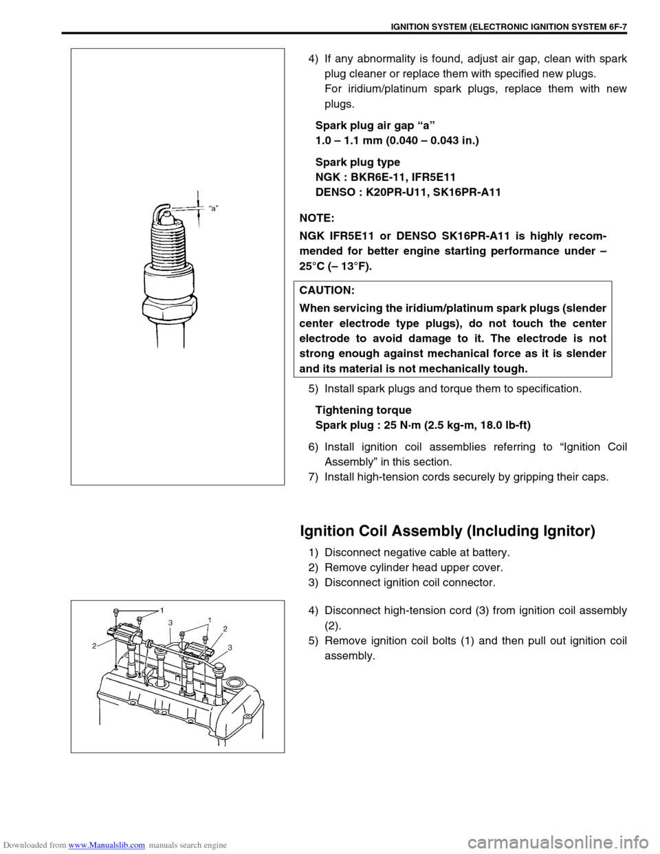
4) If any abnormality is found, adjust air gap, clean with spark
plug cleaner or replace them with specified new plugs.
For iridium/platinum spark plugs, replace them with new
plugs.
Spark plug air gap “a”
1.0 – 1.1 mm (0.040 – 0.043 in.)
Spark plug type
NGK : BKR6E-11, IFR5E11
DENSO : K20PR-U11, SK16PR-A11
5) Install spark plugs and torque them to specification.
Tightening torque
Spark plug : 25 N·m (2.5 kg-m, 18.0 lb-ft)
6) Install ignition coil assemblies referring to “Ignition Coil
Assembly” in this section.
7) Install high-tension cords securely by gripping their caps.
Ignition Coil Assembly (Including Ignitor)
1) Disconnect negative cable at battery.
2) Remove cylinder head upper cover.
3) Disconnect ignition coil connector.
4) Disconnect high-tension cord (3) from ignition coil assembly
(2).
5) Remove ignition coil bolts (1) and then pull out ignition coil
assembly. NOTE:
NGK IFR5E11 or DENSO SK16PR-A11 is highly recom-
mended for better engine starting performance under –
25°C (– 13°F).
CAUTION:
When servicing the iridium/platinum spark plugs (slender
center electrode type plugs), do not touch the center
electrode to avoid damage to it. The electrode is not
strong enough against mechanical force as it is slender
and its material is not mechanically tough.
Page 657 of 687

Downloaded from www.Manualslib.com manuals search engine 6F-8 IGNITION SYSTEM (ELECTRONIC IGNITION SYSTEM)
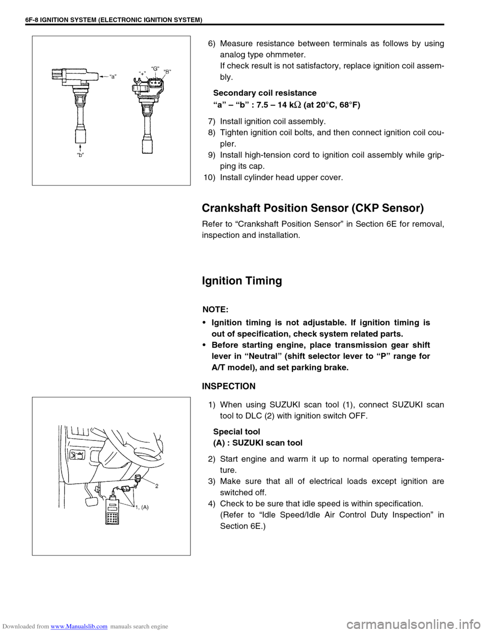
6) Measure resistance between terminals as follows by using
analog type ohmmeter.
If check result is not satisfactory, replace ignition coil assem-
bly.
Secondary coil resistance
“a” – “b” : 7.5 – 14 k
Ω (at 20°C, 68°F)
7) Install ignition coil assembly.
8) Tighten ignition coil bolts, and then connect ignition coil cou-
pler.
9) Install high-tension cord to ignition coil assembly while grip-
ping its cap.
10) Install cylinder head upper cover.
Crankshaft Position Sensor (CKP Sensor)
Refer to “Crankshaft Position Sensor” in Section 6E for removal,
inspection and installation.
Ignition Timing
INSPECTION
1) When using SUZUKI scan tool (1), connect SUZUKI scan
tool to DLC (2) with ignition switch OFF.
Special tool
(A) : SUZUKI scan tool
2) Start engine and warm it up to normal operating tempera-
ture.
3) Make sure that all of electrical loads except ignition are
switched off.
4) Check to be sure that idle speed is within specification.
(Refer to “Idle Speed/Idle Air Control Duty Inspection” in
Section 6E.)
NOTE:
Ignition timing is not adjustable. If ignition timing is
out of specification, check system related parts.
Before starting engine, place transmission gear shift
lever in “Neutral” (shift selector lever to “P” range for
A/T model), and set parking brake.
Page 660 of 687

Downloaded from www.Manualslib.com manuals search engine CRANKING SYSTEM 6G-1
6F1
6F2
6H
7C1
7D
7E
7C1
7B1
7C1
7D
7E
7F
8A
8B
8C
8D
8E
6G
7A1
10A
10B
SECTION 6G
CRANKING SYSTEM
CONTENTS
General Description ....................................... 6G-2
Cranking Circuit ............................................ 6G-2
Diagnosis ........................................................ 6G-2
Diagnosis Table ........................................... 6G-2Performance Test .........................................6G-4
On-Vehicle Service .........................................6G-5
Starting Motor ...............................................6G-5
Specifications..................................................6G-7
WARNING:
For vehicles equipped with Supplemental Restraint (Air Bag) System:
Service on and around the air bag system components or wiring must be performed only by an
authorized SUZUKI dealer. Refer to “Air Bag System Components and Wiring Location View” under
“General Description” in air bag system section in order to confirm whether you are performing ser-
vice on or near the air bag system components or wiring. Please observe all WARNINGS and “Ser-
vice Precautions” under “On-Vehicle Service” in air bag system section before performing service
on or around the air bag system components or wiring. Failure to follow WARNINGS could result in
unintentional activation of the system or could render the system inoperative. Either of these two
conditions may result in severe injury.
Technical service work must be started at least 90 seconds after the ignition switch is turned to the
“LOCK” position and the negative cable is disconnected from the battery. Otherwise, the system
may be activated by reserve energy in the Sensing and Diagnostic Module (SDM).
NOTE:
Starting motor varies depending on specifications, etc. Therefore, be sure to check model and speci-
fication of vehicle being serviced before replacing parts.