2005 SUZUKI JIMNY oil
[x] Cancel search: oilPage 583 of 687

Downloaded from www.Manualslib.com manuals search engine 6B-6 ENGINE COOLING
Maintenance
Coolant
The coolant recovery system is standard. The coolant in the radiator expands with heat, and the overflow is col-
lected in the reservoir.
When the system cools down, the coolant is drawn back into the radiator.
The cooling system has been filled at the factory with a quality coolant that is either 50/50 mixture of water and
anti-freeze / anti-corrosion coolant (ethylene glycol antifreeze).
The 50/50 mixture coolant solution provides freezing protection to – 36 °C ( – 33 °F).
Maintain cooling system freeze protection at – 36 °C ( – 33 °F) to ensure protection against corrosion and
loss of coolant from boiling.
This should be done even if freezing temperatures are not expected.
Add ethylene glycol base coolant when coolant has to be added because of coolant loss or to provide added
protection against freezing at temperature lower than – 36 °C ( – 33 °F).
Anti-freeze proportioning table
Coolant capacity Freezing temperature°C– 16– 36
°F3– 33
Anti-freeze / Anti-corrosion
coolant concentration%30 50
Ratio of compound
to cooling waterItr. 1.35/3.15 2.25/2.25
US pt. 2.85/6.65 4.75/4.75
Imp pt. 2.37/5.53 3.95/3.95
Engine radiator and heater 5.2 liters (11.0/9.2 US/lmp. pt.)
Reservoir 0.7 liters (1.5/1.2 US/lmp. pt.)
Total 5.9 liters (12.5/10.5 US/lmp. pt.)
NOTE:
Alcohol or methanol base coolant or plain water alone should not be used in cooling system at any
time as damage to cooling system could occur.
Even in a market where no freezing temperature is anticipated, mixture of 70% water and 30% ethyl-
ene glycol antifreeze (Antifreeze / Anticorrosion coolant) should be used for the purpose of corro-
sion protection and lubrication.
Page 584 of 687
Downloaded from www.Manualslib.com manuals search engine ENGINE COOLING 6B-7
Coolant Level
To check level, look at “see-through” reservoir.
It is not necessary to remove radiator cap to check coolant level.
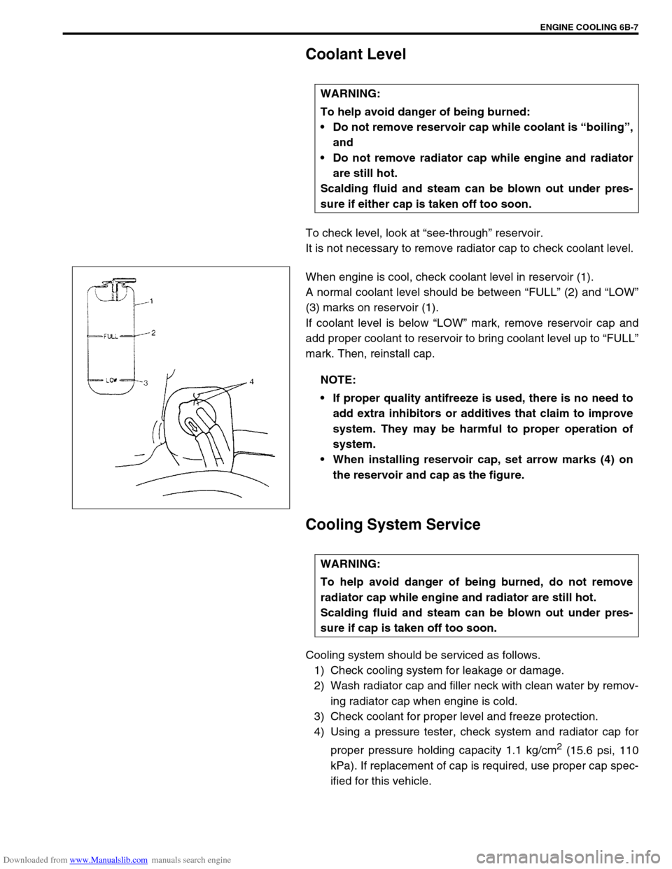
When engine is cool, check coolant level in reservoir (1).
A normal coolant level should be between “FULL” (2) and “LOW”
(3) marks on reservoir (1).
If coolant level is below “LOW” mark, remove reservoir cap and
add proper coolant to reservoir to bring coolant level up to “FULL”
mark. Then, reinstall cap.
Cooling System Service
Cooling system should be serviced as follows.
1) Check cooling system for leakage or damage.
2) Wash radiator cap and filler neck with clean water by remov-
ing radiator cap when engine is cold.
3) Check coolant for proper level and freeze protection.
4) Using a pressure tester, check system and radiator cap for
proper pressure holding capacity 1.1 kg/cm
2 (15.6 psi, 110
kPa). If replacement of cap is required, use proper cap spec-
ified for this vehicle. WARNING:
To help avoid danger of being burned:
Do not remove reservoir cap while coolant is “boiling”,
and
Do not remove radiator cap while engine and radiator
are still hot.
Scalding fluid and steam can be blown out under pres-
sure if either cap is taken off too soon.
NOTE:
If proper quality antifreeze is used, there is no need to
add extra inhibitors or additives that claim to improve
system. They may be harmful to proper operation of
system.
When installing reservoir cap, set arrow marks (4) on
the reservoir and cap as the figure.
WARNING:
To help avoid danger of being burned, do not remove
radiator cap while engine and radiator are still hot.
Scalding fluid and steam can be blown out under pres-
sure if cap is taken off too soon.
Page 590 of 687
Downloaded from www.Manualslib.com manuals search engine ENGINE COOLING 6B-13
Water Pump Belt and Cooling Fan
REMOVAL
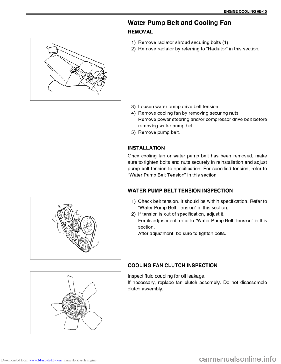
1) Remove radiator shroud securing bolts (1).
2) Remove radiator by referring to “Radiator” in this section.
3) Loosen water pump drive belt tension.
4) Remove cooling fan by removing securing nuts.
Remove power steering and/or compressor drive belt before
removing water pump belt.
5) Remove pump belt.
INSTALLATION
Once cooling fan or water pump belt has been removed, make
sure to tighten bolts and nuts securely in reinstallation and adjust
pump belt tension to specification. For specified tension, refer to
“Water Pump Belt Tension” in this section.
WATER PUMP BELT TENSION INSPECTION
1) Check belt tension. It should be within specification. Refer to
“Water Pump Belt Tension” in this section.
2) If tension is out of specification, adjust it.
For its adjustment, refer to “Water Pump Belt Tension” in this
section.
After adjustment, be sure to tighten bolts.
COOLING FAN CLUTCH INSPECTION
Inspect fluid coupling for oil leakage.
If necessary, replace fan clutch assembly. Do not disassemble
clutch assembly.
Page 600 of 687
Downloaded from www.Manualslib.com manuals search engine ENGINE FUEL 6C-5
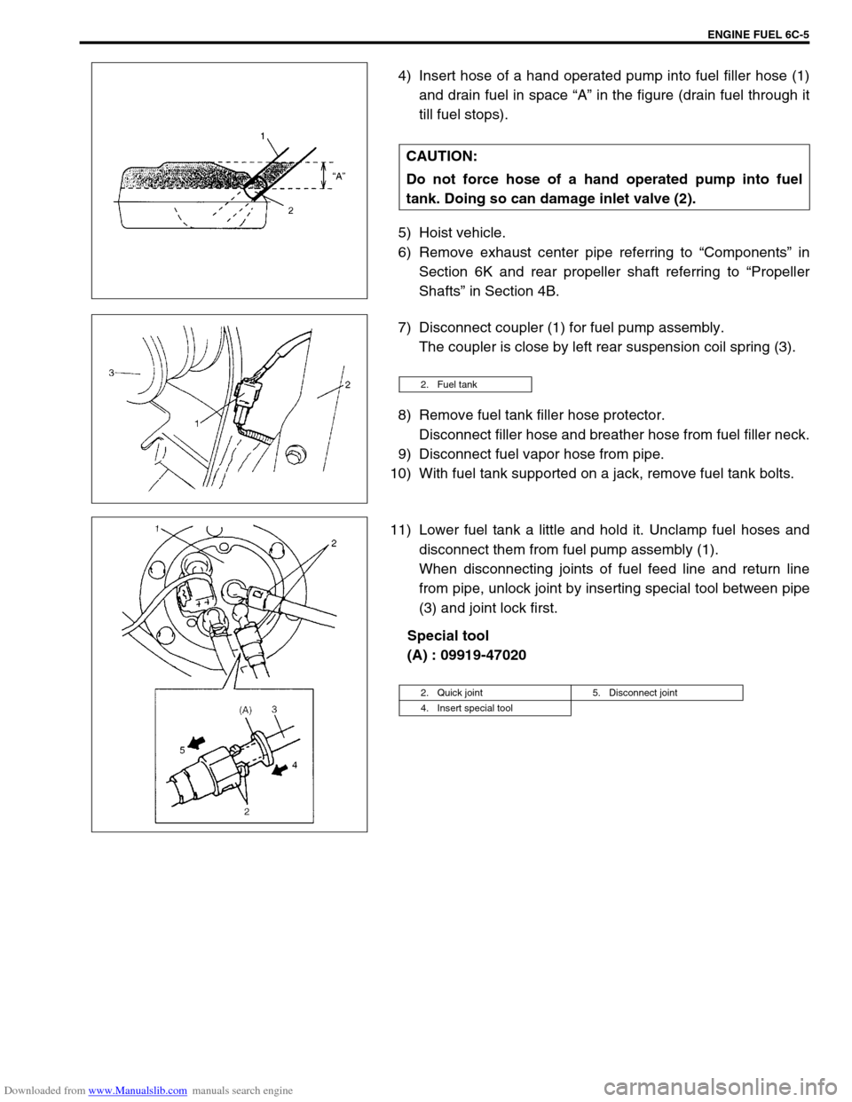
4) Insert hose of a hand operated pump into fuel filler hose (1)
and drain fuel in space “A” in the figure (drain fuel through it
till fuel stops).
5) Hoist vehicle.
6) Remove exhaust center pipe referring to “Components” in
Section 6K and rear propeller shaft referring to “Propeller
Shafts” in Section 4B.
7) Disconnect coupler (1) for fuel pump assembly.
The coupler is close by left rear suspension coil spring (3).
8) Remove fuel tank filler hose protector.
Disconnect filler hose and breather hose from fuel filler neck.
9) Disconnect fuel vapor hose from pipe.
10) With fuel tank supported on a jack, remove fuel tank bolts.
11) Lower fuel tank a little and hold it. Unclamp fuel hoses and
disconnect them from fuel pump assembly (1).
When disconnecting joints of fuel feed line and return line
from pipe, unlock joint by inserting special tool between pipe
(3) and joint lock first.
Special tool
(A) : 09919-47020 CAUTION:
Do not force hose of a hand operated pump into fuel
tank. Doing so can damage inlet valve (2).
2. Fuel tank
2. Quick joint 5. Disconnect joint
4. Insert special tool
Page 603 of 687

Downloaded from www.Manualslib.com manuals search engine 6C-8 ENGINE FUEL
INSPECTION
Check fuel pump assembly for damage.
Check fuel suction filter (1) for evidence of dirt and contamination.
If present, replace or clean and check for presence of dirt in fuel
tank.
For inspection of fuel pump itself, refer to “Table B – 3 Fuel Pres-
sure Check” in Section 6.
For inspection of fuel level gauge, refer to “Fuel Meter / Fuel
Gauge Unit” in Section 8.
DISASSEMBLY / REASSEMBLY
2. Fuel filter & bracket assembly
3. Fuel pump motor & level gauge assembly
“A” : Apply oil 4. Housing 8. Cushion
1. Bracket sub assembly (including fuel filter) 5. Lead wire 9. Bracket
2. Grommet 6. Fuel level gauge 10. Spacer
3. Tube 7. Fuel pump
Page 610 of 687
Downloaded from www.Manualslib.com manuals search engine ENGINE AND EMISSION CONTROL SYSTEM 6E-5
Air Intake System
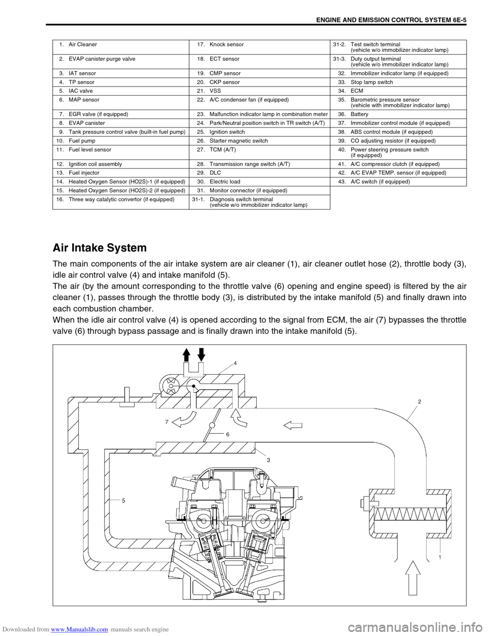
The main components of the air intake system are air cleaner (1), air cleaner outlet hose (2), throttle body (3),
idle air control valve (4) and intake manifold (5).
The air (by the amount corresponding to the throttle valve (6) opening and engine speed) is filtered by the air
cleaner (1), passes through the throttle body (3), is distributed by the intake manifold (5) and finally drawn into
each combustion chamber.
When the idle air control valve (4) is opened according to the signal from ECM, the air (7) bypasses the throttle
valve (6) through bypass passage and is finally drawn into the intake manifold (5).
1. Air Cleaner 17. Knock sensor 31-2. Test switch terminal
(vehicle w/o immobilizer indicator lamp)
2. EVAP canister purge valve 18. ECT sensor 31-3. Duty output terminal
(vehicle w/o immobilizer indicator lamp)
3. IAT sensor 19. CMP sensor 32. Immobilizer indicator lamp (if equipped)
4. TP sensor 20. CKP sensor 33. Stop lamp switch
5. IAC valve 21. VSS 34. ECM
6. MAP sensor 22. A/C condenser fan (if equipped) 35. Barometric pressure sensor
(vehicle with immobilizer indicator lamp)
7. EGR valve (if equipped) 23. Malfunction indicator lamp in combination meter 36. Battery
8. EVAP canister 24. Park/Neutral position switch in TR switch (A/T) 37. Immobilizer control module (if equipped)
9. Tank pressure control valve (built-in fuel pump) 25. Ignition switch 38. ABS control module (if equipped)
10. Fuel pump 26. Starter magnetic switch 39. CO adjusting resistor (if equipped)
11. Fuel level sensor 27. TCM (A/T) 40. Power steering pressure switch
(if equipped)
12. Ignition coil assembly 28. Transmission range switch (A/T) 41. A/C compressor clutch (if equipped)
13. Fuel injector 29. DLC 42. A/C EVAP TEMP. sensor (if equipped)
14. Heated Oxygen Sensor (HO2S)-1 (if equipped) 30. Electric load 43. A/C switch (if equipped)
15. Heated Oxygen Sensor (HO2S)-2 (if equipped) 31. Monitor connector (if equipped)
16. Three way catalytic convertor (if equipped) 31-1. Diagnosis switch terminal
(vehicle w/o immobilizer indicator lamp)
Page 612 of 687
Downloaded from www.Manualslib.com manuals search engine ENGINE AND EMISSION CONTROL SYSTEM 6E-7
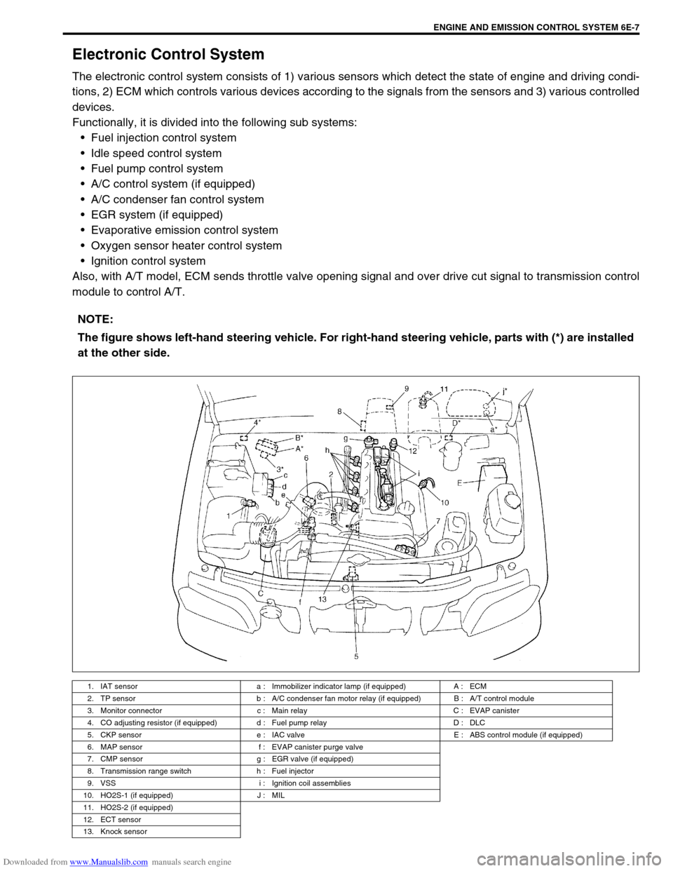
Electronic Control System
The electronic control system consists of 1) various sensors which detect the state of engine and driving condi-
tions, 2) ECM which controls various devices according to the signals from the sensors and 3) various controlled
devices.
Functionally, it is divided into the following sub systems:
Fuel injection control system
Idle speed control system
Fuel pump control system
A/C control system (if equipped)
A/C condenser fan control system
EGR system (if equipped)
Evaporative emission control system
Oxygen sensor heater control system
Ignition control system
Also, with A/T model, ECM sends throttle valve opening signal and over drive cut signal to transmission control
module to control A/T.
NOTE:
The figure shows left-hand steering vehicle. For right-hand steering vehicle, parts with (*) are installed
at the other side.
1. IAT sensor a : Immobilizer indicator lamp (if equipped) A : ECM
2. TP sensor b : A/C condenser fan motor relay (if equipped) B : A/T control module
3. Monitor connector c : Main relay C : EVAP canister
4. CO adjusting resistor (if equipped) d : Fuel pump relay D : DLC
5. CKP sensor e : IAC valve E : ABS control module (if equipped)
6. MAP sensor f : EVAP canister purge valve
7. CMP sensor g : EGR valve (if equipped)
8. Transmission range switch h : Fuel injector
9. VSS i : Ignition coil assemblies
10. HO2S-1 (if equipped) J : MIL
11. HO2S-2 (if equipped)
12. ECT sensor
13. Knock sensor
Page 613 of 687

Downloaded from www.Manualslib.com manuals search engine 6E-8 ENGINE AND EMISSION CONTROL SYSTEM
Engine & emission control input / output table
INPUTOUTPUT
ELECTRIC CONTROL DEVICE
DIAGNOSIS SWITCH TERMINAL
(VEHICLE WITHOUT IMMOBILIZER INDICATOR LAMP)
BAROMETRIC PRESSURE SENSOR
(VEHICLE WITH IMMOBILIZER INDICATOR LAMP)
STOP LAMP SWITCH
STARTER SWITCH
IGNITION SWITCH
LIGHTING SWITCH
REAR DEFOGGER SWITCH (IF EQUIPPED)
BLOWER SWITCH
A/C SWITCH (IF EQUIPPED)
A/C EVAPORATOR TEMP. SENSOR (IF EQUIPPED)
VSS
HEATED OXYGEN SENSOR-1 (IF EQUIPPED)
HEATED OXYGEN SENSOR-2
(IF EQUIPPED)For detecting deterioration of
three way catalytic converter
IAT SENSOR
ECT SENSOR
TP SENSOR
MAP SENSOR
CMP SENSOR
CKP SENSOR
TEST SWITCH TERMINAL
(VEHICLE WITHOUT IMMOBILIZER INDICATOR LAMP)
KNOCK SENSOR
FUEL PUMP RELAY
FUEL INJECTOR
HO2S HEATER
IAC VALVE
IGNITION COIL WITH IGNITER
EGR VALVE (IF EQUIPPED)
EVAP CANISTER PURGE VALVE
A/C COMPRESSOR CLUTCH
MIL
MAIN RELAY
TRANSMISSION CONTROL MODULE SIGNAL FROM SENSOR, SWITCH AND CONTROL MODULEA/C CONDENSER FAN RELAY