Page 485 of 687
Downloaded from www.Manualslib.com manuals search engine 6A1-4 ENGINE MECHANICAL (M13 ENGINE)
Diagnosis
Diagnosis Table
Refer to “Engine Diagnosis Table” in Section 6.
Compression Check
Check compression pressure on all 4 cylinders as follows:
1) Warm up engine.
2) Stop engine after warming up.
3) Disconnect accelerator cable (1) from clamp (2) (For left
hand steering vehicle only).
4) Remove cylinder head upper cover (3).
5) Disconnect ignition coil couplers (1).
6) Remove ignition coil assemblies (2) with high-tension cord
(3).
7) Remove all spark plugs.
8) Disconnect fuel injector wires (4) at the coupler.
9) Install special tools (Compression gauge) into spark plug
hole.
Special tool
(A) : 09915-64510-001
(B) : 09915-64510-002
(C) : 09915-64530
(D) : 09915-67010 NOTE:
After warming up engine, place transmission gear shift
lever in “Neutral” (shift selector lever to “P” range for A/T
model), and set parking brake and block drive wheels.
Page 488 of 687

Downloaded from www.Manualslib.com manuals search engine ENGINE MECHANICAL (M13 ENGINE) 6A1-7
Oil Pressure Check
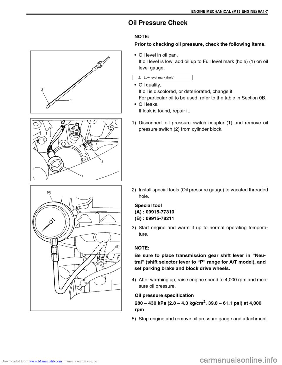
Oil level in oil pan.
If oil level is low, add oil up to Full level mark (hole) (1) on oil
level gauge.
Oil quality.
If oil is discolored, or deteriorated, change it.
For particular oil to be used, refer to the table in Section 0B.
Oil leaks.
If leak is found, repair it.
1) Disconnect oil pressure switch coupler (1) and remove oil
pressure switch (2) from cylinder block.
2) Install special tools (Oil pressure gauge) to vacated threaded
hole.
Special tool
(A) : 09915-77310
(B) : 09915-78211
3) Start engine and warm it up to normal operating tempera-
ture.
4) After warming up, raise engine speed to 4,000 rpm and mea-
sure oil pressure.
Oil pressure specification
280 – 430 kPa (2.8 – 4.3 kg/cm
2, 39.8 – 61.1 psi) at 4,000
rpm
5) Stop engine and remove oil pressure gauge and attachment.NOTE:
Prior to checking oil pressure, check the following items.
2. Low level mark (hole)
NOTE:
Be sure to place transmission gear shift lever in “Neu-
tral” (shift selector lever to “P” range for A/T model), and
set parking brake and block drive wheels.
Page 490 of 687

Downloaded from www.Manualslib.com manuals search engine ENGINE MECHANICAL (M13 ENGINE) 6A1-9
Valve Lash (Clearance)
1) Remove negative cable at battery.
2) Remove cylinder head cover referring to “Cylinder Head
Cover” in this section.
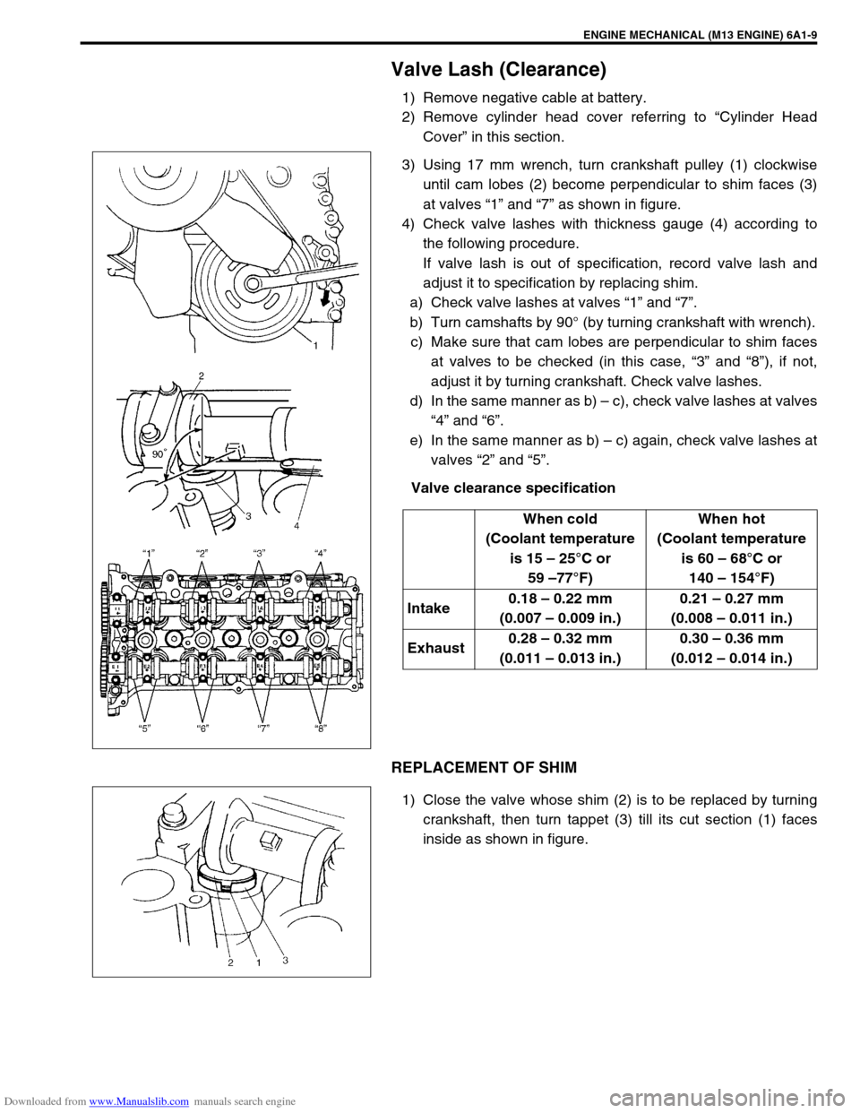
3) Using 17 mm wrench, turn crankshaft pulley (1) clockwise
until cam lobes (2) become perpendicular to shim faces (3)
at valves “1” and “7” as shown in figure.
4) Check valve lashes with thickness gauge (4) according to
the following procedure.
If valve lash is out of specification, record valve lash and
adjust it to specification by replacing shim.
a) Check valve lashes at valves “1” and “7”.
b) Turn camshafts by 90° (by turning crankshaft with wrench).
c) Make sure that cam lobes are perpendicular to shim faces
at valves to be checked (in this case, “3” and “8”), if not,
adjust it by turning crankshaft. Check valve lashes.
d) In the same manner as b) – c), check valve lashes at valves
“4” and “6”.
e) In the same manner as b) – c) again, check valve lashes at
valves “2” and “5”.
Valve clearance specification
REPLACEMENT OF SHIM
1) Close the valve whose shim (2) is to be replaced by turning
crankshaft, then turn tappet (3) till its cut section (1) faces
inside as shown in figure.When cold
(Coolant temperature
is 15 – 25°C or
59 –77°F)When hot
(Coolant temperature
is 60 – 68°C or
140 – 154°F)
Intake0.18 – 0.22 mm
(0.007 – 0.009 in.)0.21 – 0.27 mm
(0.008 – 0.011 in.)
Exhaust0.28 – 0.32 mm
(0.011 – 0.013 in.)0.30 – 0.36 mm
(0.012 – 0.014 in.)
Page 493 of 687
Downloaded from www.Manualslib.com manuals search engine 6A1-12 ENGINE MECHANICAL (M13 ENGINE)
8) Lift valve by turning crankshaft counterclockwise (in opposite
direction against above Step 4) and remove special tool.
Special tool
(A) : 09916-67020
9) Install camshaft housing (1) and tighten them to specified
torque.
Tightening torque
Camshaft housing bolts (a) : 11 N·m (1.1 kg-m, 8.0 lb-ft)
10) Check valve clearance again.
11) Install cylinder head cover, referring to “Cylinder Head
Cover” in this section.
1. Tappet
2. Camshaft
Page 495 of 687
Downloaded from www.Manualslib.com manuals search engine 6A1-14 ENGINE MECHANICAL (M13 ENGINE)
Air Cleaner Assembly
REMOVAL
1) Disconnect negative cable at battery.
2) Disconnect IAT sensor coupler (1).
3) Disconnect breather hose from air cleaner outlet No.2 hose
(2).
4) Remove air cleaner outlet No.2 hose fastening bolt (3).
5) Loosen air cleaner outlet No.2 hose clamp bolt (4).
6) Remove air cleaner case fastening bolts (5).
7) Remove air cleaner assembly with outlet hoses.
INSTALLATION
Reverse removal procedure for installation.
Knock Sensor
REMOVAL
1) Disconnect negative cable at battery.
2) Remove intake manifold referring to “Throttle Body and
Intake Manifold” in this section.
3) Disconnect knock sensor connector (1).
4) Remove knock sensor (2) from cylinder block.
INSPECTION
Check sensor for damage.
If any faulty is found, replace.
INSTALLATION
Reverse removal procedure for installation.
Tightening torque
Knock sensor (a) : 23 N·m (2.3 kg-m, 16.5 lb-ft)
Page 499 of 687

Downloaded from www.Manualslib.com manuals search engine 6A1-18 ENGINE MECHANICAL (M13 ENGINE)
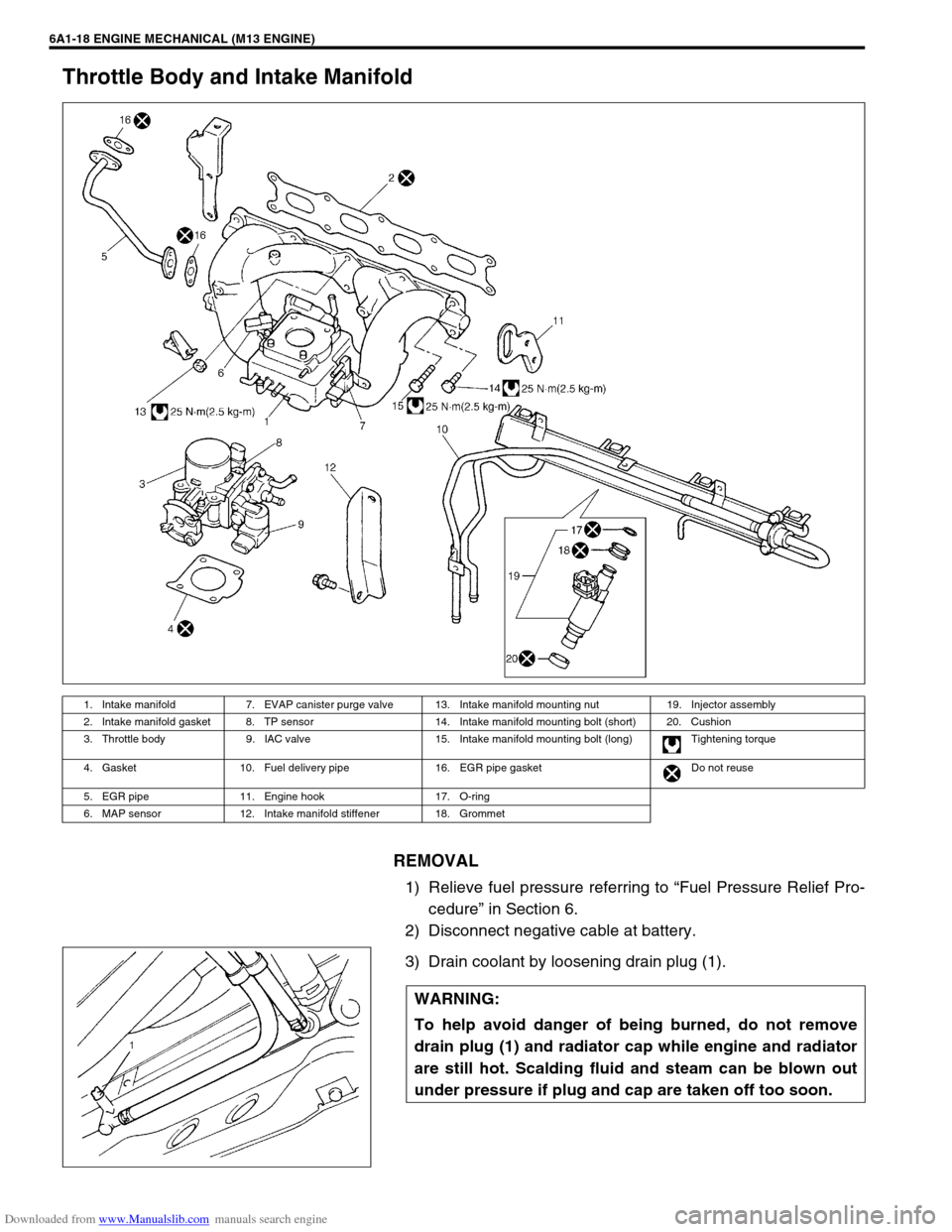
Throttle Body and Intake Manifold
REMOVAL
1) Relieve fuel pressure referring to “Fuel Pressure Relief Pro-
cedure” in Section 6.
2) Disconnect negative cable at battery.
3) Drain coolant by loosening drain plug (1).
1. Intake manifold 7. EVAP canister purge valve 13. Intake manifold mounting nut 19. Injector assembly
2. Intake manifold gasket 8. TP sensor 14. Intake manifold mounting bolt (short) 20. Cushion
3. Throttle body 9. IAC valve 15. Intake manifold mounting bolt (long) Tightening torque
4. Gasket 10. Fuel delivery pipe 16. EGR pipe gasket Do not reuse
5. EGR pipe 11. Engine hook 17. O-ring
6. MAP sensor 12. Intake manifold stiffener 18. Grommet
WARNING:
To help avoid danger of being burned, do not remove
drain plug (1) and radiator cap while engine and radiator
are still hot. Scalding fluid and steam can be blown out
under pressure if plug and cap are taken off too soon.
Page 501 of 687
Downloaded from www.Manualslib.com manuals search engine 6A1-20 ENGINE MECHANICAL (M13 ENGINE)
13) Remove intake manifold (1) with throttle body (2) and EGR
pipe (3) from cylinder head (4), and then its gasket.
INSTALLATION
Reverse removal procedure for installation noting the followings.
Use new intake manifold gasket and EGR pipe gasket.
Tighten long bolt (1), short bolt (3) and nuts (2) to specified
torque.
Tightening torque
Intake manifold bolts and nuts
(a) : 25 N·m (2.5 kg-m, 18.0 lb-ft)
Check to ensure that all removed parts are back in place.
Reinstall any necessary parts which have not been rein-
stalled.
Adjust accelerator cable play referring to “Accelerator Cable
Adjustment” in Section 6E.
Refill cooling system referring to “Cooling System Flush and
Refill” in Section 6B.
Upon completion of installation, turn ignition switch ON but
engine OFF and check for fuel leaks.
Finally, start engine and check for engine coolant leaks.
Page 508 of 687
Downloaded from www.Manualslib.com manuals search engine ENGINE MECHANICAL (M13 ENGINE) 6A1-27
6) Lower engine and tighten engine mounting bracket bolts to
specified torque.
Tightening torque
Engine mounting bracket bolts
(a) : 50 N·m (5.0 kg-m, 36.5 lb-ft)
7) Install oil level gauge.
8) Refill engine with engine oil referring to “Engine Oil and Filter
Change” in Section 0B.
9) Verify that there is no engine oil leakage at each connection.