Page 207 of 687
Downloaded from www.Manualslib.com manuals search engine 3D-34 FRONT SUSPENSION
4) Install axle shaft (2) to front axle housing (1) (for 4WD).
5) Install knuckle to front axle housing. For details, refer to
“Steering Knuckle / Wheel Spindle” in this section.
6) Refill front axle (differential) housing with new specified gear
oil (for 4WD). Refer to “Maintenance Service” in Section 7E
for refill.
7) After servicing, check that no oil leakage exists.
Steering Knuckle Seal
REMOVAL
1) Hoist vehicle.
2) Remove knuckle seal cover bolts and seal cover (1).
3) Cut oil seal in place with scissors or knife, and take it off.
INSTALLATION
1) Cut replacement oil seal at one place with scissors or a
knife.
Page 208 of 687

Downloaded from www.Manualslib.com manuals search engine FRONT SUSPENSION 3D-35
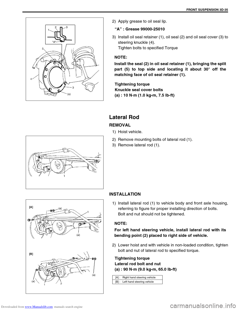
2) Apply grease to oil seal lip.
“A” : Grease 99000-25010
3) Install oil seal retainer (1), oil seal (2) and oil seal cover (3) to
steering knuckle (4).
Tighten bolts to specified Torque
Tightening torque
Knuckle seal cover bolts
(a) : 10 N·m (1.0 kg-m, 7.5 lb-ft)
Lateral Rod
REMOVAL
1) Hoist vehicle.
2) Remove mounting bolts of lateral rod (1).
3) Remove lateral rod (1).
INSTALLATION
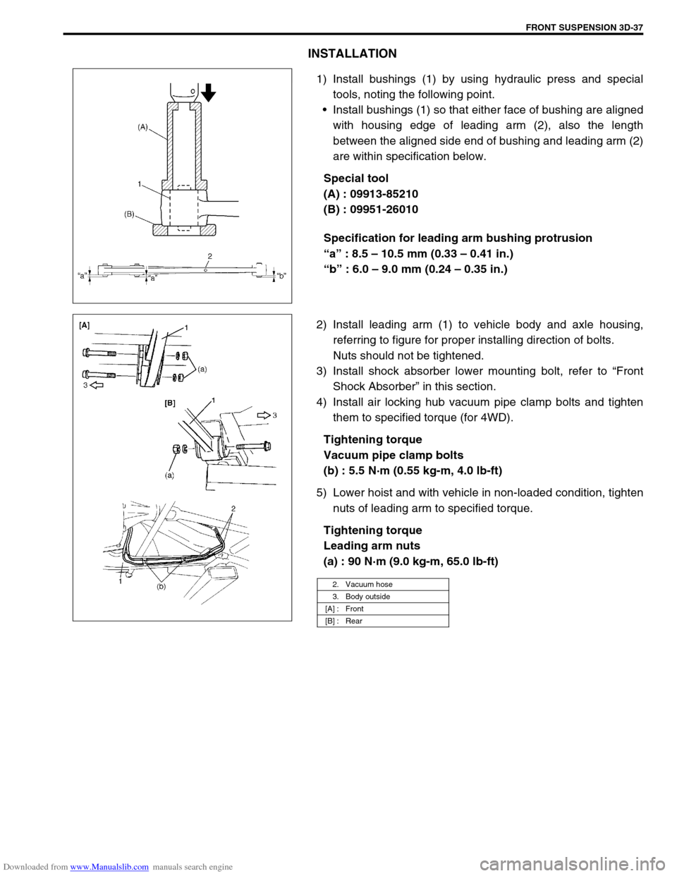
1) Install lateral rod (1) to vehicle body and front axle housing,
referring to figure for proper installing direction of bolts.
Bolt and nut should not be tightened.
2) Lower hoist and with vehicle in non-loaded condition, tighten
bolt and nut of lateral rod to specified torque.
Tightening torque
Lateral rod bolt and nut
(a) : 90 N·m (9.0 kg-m, 65.0 lb-ft) NOTE:
Install the seal (2) in oil seal retainer (1), bringing the split
part (5) to top side and locating it about 30° off the
matching face of oil seal retainer (1).
NOTE:
For left hand steering vehicle, install lateral rod with its
bending point (2) placed to right side of vehicle.
[A] : Right hand steering vehicle
[B] : Left hand steering vehicle
Page 209 of 687
Downloaded from www.Manualslib.com manuals search engine 3D-36 FRONT SUSPENSION
Leading Arm / Bushing
REMOVAL
1) Hoist vehicle.
2) Remove air locking hub vacuum pipe clamp bolts (2) (for
4WD).
3) Support front axle housing by using floor jack.
4) Remove shock absorber lower mounting bolt, refer to “Front
Shock Absorber” in this section.
5) Remove mounting bolts and leading arm (1).
6) Remove bushings by using hydraulic press and special
tools.
Special tool
(A) : 09924-74510
(B) : 09951-16030
(C) : 09951-26010
1. Leading arm (right side)
Page 210 of 687

Downloaded from www.Manualslib.com manuals search engine FRONT SUSPENSION 3D-37
INSTALLATION
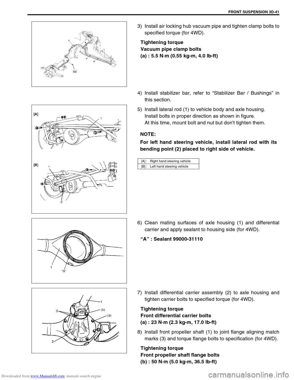
1) Install bushings (1) by using hydraulic press and special
tools, noting the following point.
Install bushings (1) so that either face of bushing are aligned
with housing edge of leading arm (2), also the length
between the aligned side end of bushing and leading arm (2)
are within specification below.
Special tool
(A) : 09913-85210
(B) : 09951-26010
Specification for leading arm bushing protrusion
“a” : 8.5 – 10.5 mm (0.33 – 0.41 in.)
“b” : 6.0 – 9.0 mm (0.24 – 0.35 in.)
2) Install leading arm (1) to vehicle body and axle housing,
referring to figure for proper installing direction of bolts.
Nuts should not be tightened.
3) Install shock absorber lower mounting bolt, refer to “Front
Shock Absorber” in this section.
4) Install air locking hub vacuum pipe clamp bolts and tighten
them to specified torque (for 4WD).
Tightening torque
Vacuum pipe clamp bolts
(b) : 5.5 N·m (0.55 kg-m, 4.0 lb-ft)
5) Lower hoist and with vehicle in non-loaded condition, tighten
nuts of leading arm to specified torque.
Tightening torque
Leading arm nuts
(a) : 90 N·m (9.0 kg-m, 65.0 lb-ft)
2. Vacuum hose
3. Body outside
[A] : Front
[B] : Rear
Page 211 of 687
Downloaded from www.Manualslib.com manuals search engine 3D-38 FRONT SUSPENSION
Front Axle Housing
REMOVAL
1) Hoist vehicle.
2) Remove front wheels.
3) Drain front differential gear oil (for 4WD).
4) Remove caliper carrier bolts (R&L) and suspend caliper.
5) Remove right and left brake disc.
6) Remove wheel speed sensor (if equipped with ABS).
7) Disconnect spindle vacuum hoses from wheel spindle (for
4WD).
8) Remove tie rod (and drag rod) end nuts and disconnect tie
rod (and drag rod) ends (2) from knuckle arm (1) (R&L) with
special tool.
Special tool
(A) : 09913-65210 CAUTION:
During removal, be careful not to damage brake flexible
hose and not to depress brake pedal.
NOTE:
If brake disc can not be removed by hand, use 8mm bolts
(1).
CAUTION:
Give match mark to spindle vacuum hose and wheel
spindle before removal.
1. Vacuum hose to lock
2. Vacuum hose to unlock
Page 212 of 687

Downloaded from www.Manualslib.com manuals search engine FRONT SUSPENSION 3D-39
9) Remove knuckle seal cover bolts, take off knuckle seal cover
(1), knuckle seal and knuckle seal retainer.
10) Remove upper and lower kingpins (2) from steering knuckle.
11) Remove knuckle with hub assembly from axle housing (for
2WD model) or draw out right and left axle shafts with
knuckle and hub assembly (for 4WD model).
12) Before removing front propeller shaft (1), give match marks
(3) on joint flange (2) and front propeller shaft as shown (for
4WD).
13) Remove front differential from front axle housing (for 4WD).
14) Remove air locking hub vacuum pipe from axle housing (1)
(for 4WD).
15) Support front axle housing by using floor jack.
16) Remove lateral rod, refer to “Lateral Rod” in this section.
17) Remove stabilizer bar, refer to “Stabilizer Bar / Bushings” in
this section.
18) Loosen mounting nuts of leading arm (1) but don’t remove
bolts. NOTE:
The removed upper and lower kingpins (2) must be kept
separated so as to prevent an error when putting them
back in their place in reassembly.
NOTE:
At this time, lower kingpin bearing sometimes falls off.
So remove bearing while pulling off knuckle gradually.
Page 213 of 687
Downloaded from www.Manualslib.com manuals search engine 3D-40 FRONT SUSPENSION
19) Lower floor jack until tension of suspension coil spring
becomes a little loose and remove right and left sides lower
mounting bolt of shock absorber (1).
20) Remove front mounting bolts of leading arm.
21) Lower front axle housing gradually.
22) Remove axle housing.
INSTALLATION
1) Place rear axle housing on floor jack. Then install leading
arm front mounting bolts (right & left) in proper direction as
shown. At this time, mount nuts but don’t tighten them.
2) Install lower part of shock absorber (1) to right and left sides
of axle housing and install bolts (2) in proper direction as
shown in figure. At this time, mount nuts (3) but don’t tighten
them.
A : Body outside
Page 214 of 687

Downloaded from www.Manualslib.com manuals search engine FRONT SUSPENSION 3D-41
3) Install air locking hub vacuum pipe and tighten clamp bolts to
specified torque (for 4WD).
Tightening torque
Vacuum pipe clamp bolts
(a) : 5.5 N·m (0.55 kg-m, 4.0 lb-ft)
4) Install stabilizer bar, refer to “Stabilizer Bar / Bushings” in
this section.
5) Install lateral rod (1) to vehicle body and axle housing.
Install bolts in proper direction as shown in figure.
At this time, mount bolt and nut but don't tighten them.
6) Clean mating surfaces of axle housing (1) and differential
carrier and apply sealant to housing side (for 4WD).
“A” : Sealant 99000-31110
7) Install differential carrier assembly (2) to axle housing and
tighten carrier bolts to specified torque (for 4WD).
Tightening torque
Front differential carrier bolts
(a) : 23 N·m (2.3 kg-m, 17.0 lb-ft)
8) Install front propeller shaft (1) to joint flange aligning match
marks (3) and torque flange bolts to specification (for 4WD).
Tightening torque
Front propeller shaft flange bolts
(b) : 50 N·m (5.0 kg-m, 36.5 lb-ft)
NOTE:
For left hand steering vehicle, install lateral rod with its
bending point (2) placed to right side of vehicle.
[A] : Right hand steering vehicle
[B] : Left hand steering vehicle