Page 550 of 687

Downloaded from www.Manualslib.com manuals search engine ENGINE MECHANICAL (M13 ENGINE) 6A1-69
6) If clearance can not be brought to within its limit even by
using a new standard size bearing, regrind crankpin to
undersize and use 0.25 mm undersize bearing.
ASSEMBLY
1) Install piston pin to piston (1) and connecting rod (2):
a) After applying engine oil to piston pin and piston pin holes
in piston and connecting rod.
b) Fit connecting rod as shown in figure.
c) Insert piston pin to piston and connecting rod.
d) Install piston pin circlips (3).
2) Install piston rings to piston :
a) As indicated in figure, 1st and 2nd rings have “T” mark
respectively. When installing these piston rings to piston,
direct marked side of each ring toward top of piston.
b) 1st ring (1) differs from 2nd ring (2) in thickness, shape and
color of surface contacting cylinder wall.
Distinguish 1st ring from 2nd ring by referring to figure.
c) When installing oil ring (3) install spacer first and then two
rails.
3) After installing three rings (1st, 2nd and oil rings), distribute
their end gaps as shown in figure. NOTE:
After checking the rod bearing clearance, make sure to
check connecting rod bolt diameter.
Refer to “Inspection” of “Connecting Rod”.
NOTE:
Circlip should be installed with its cut part facing as
shown in figure. Install so that circlip end gap comes
within such range as indicated by arrow.
1. Arrow mark
2. 1st ring end gap
3. 2nd ring end gap and oil ring spacer gap
4. Oil ring upper rail gap
5. Oil ring lower rail gap
Page 557 of 687
Downloaded from www.Manualslib.com manuals search engine 6A1-76 ENGINE MECHANICAL (M13 ENGINE)
26) Remove bolts and nuts fastening cylinder block and trans-
mission.
27) Install board (1) or the like on A/C condenser. This prevents
damage to condenser fins when lifting and lowering engine
assembly.
28) Install lifting device.
29) Remove right and left engine mounting bracket bolts (1).
30) Before lifting engine, check to ensure all hoses, electric
wires and cables are disconnected from engine.
31) Remove engine assembly from chassis and transmission by
lifting a little, sliding toward front side, and then carefully
hoist engine assembly.
Page 676 of 687

Downloaded from www.Manualslib.com manuals search engine CHARGING SYSTEM 6H-9
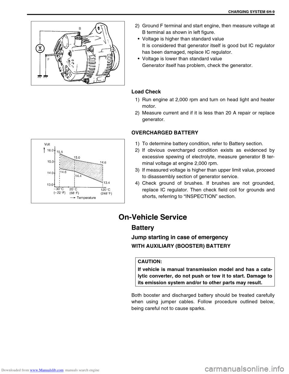
2) Ground F terminal and start engine, then measure voltage at
B terminal as shown in left figure.
Voltage is higher than standard value
It is considered that generator itself is good but IC regulator
has been damaged, replace IC regulator.
Voltage is lower than standard value
Generator itself has problem, check the generator.
Load Check
1) Run engine at 2,000 rpm and turn on head light and heater
motor.
2) Measure current and if it is less than 20 A repair or replace
generator.
OVERCHARGED BATTERY
1) To determine battery condition, refer to Battery section.
2) If obvious overcharged condition exists as evidenced by
excessive spewing of electrolyte, measure generator B ter-
minal voltage at engine 2,000 rpm.
3) If measured voltage is higher than upper limit value, proceed
to disassembly section of generator service.
4) Check ground of brushes. If brushes are not grounded,
replace IC regulator. Then check field coil for grounds and
shorts, referring to “INSPECTION” section.
On-Vehicle Service
Battery
Jump starting in case of emergency
WITH AUXILIARY (BOOSTER) BATTERY
Both booster and discharged battery should be treated carefully
when using jumper cables. Follow procedure outlined below,
being careful not to cause sparks.
CAUTION:
If vehicle is manual transmission model and has a cata-
lytic converter, do not push or tow it to start. Damage to
its emission system and/or to other parts may result.