Page 552 of 687

Downloaded from www.Manualslib.com manuals search engine ENGINE MECHANICAL (M13 ENGINE) 6A1-71
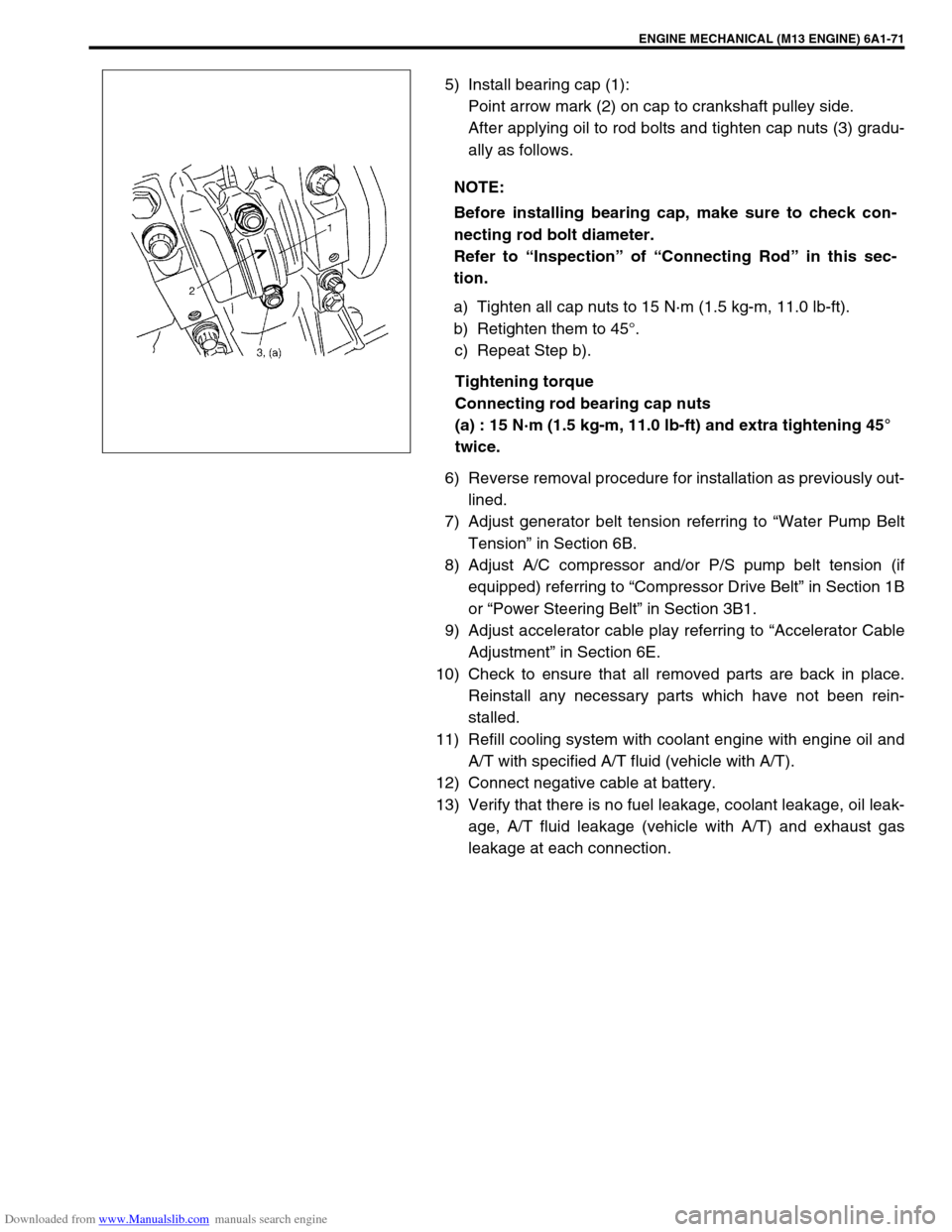
5) Install bearing cap (1):
Point arrow mark (2) on cap to crankshaft pulley side.
After applying oil to rod bolts and tighten cap nuts (3) gradu-
ally as follows.
a) Tighten all cap nuts to 15 N·m (1.5 kg-m, 11.0 lb-ft).
b) Retighten them to 45°.
c) Repeat Step b).
Tightening torque
Connecting rod bearing cap nuts
(a) : 15 N·m (1.5 kg-m, 11.0 lb-ft) and extra tightening 45°
twice.
6) Reverse removal procedure for installation as previously out-
lined.
7) Adjust generator belt tension referring to “Water Pump Belt
Tension” in Section 6B.
8) Adjust A/C compressor and/or P/S pump belt tension (if
equipped) referring to “Compressor Drive Belt” in Section 1B
or “Power Steering Belt” in Section 3B1.
9) Adjust accelerator cable play referring to “Accelerator Cable
Adjustment” in Section 6E.
10) Check to ensure that all removed parts are back in place.
Reinstall any necessary parts which have not been rein-
stalled.
11) Refill cooling system with coolant engine with engine oil and
A/T with specified A/T fluid (vehicle with A/T).
12) Connect negative cable at battery.
13) Verify that there is no fuel leakage, coolant leakage, oil leak-
age, A/T fluid leakage (vehicle with A/T) and exhaust gas
leakage at each connection. NOTE:
Before installing bearing cap, make sure to check con-
necting rod bolt diameter.
Refer to “Inspection” of “Connecting Rod” in this sec-
tion.
Page 554 of 687

Downloaded from www.Manualslib.com manuals search engine ENGINE MECHANICAL (M13 ENGINE) 6A1-73
Unit Repair Overhaul
Engine Assembly
REMOVAL
1) Relieve fuel pressure referring to “Fuel Pressure Relief Pro-
cedure” in Section 6.
2) Disconnect negative cable at battery.
3) Remove engine hood after disconnecting windshield washer
hose.
4) Remove A/C compressor and/or P/S pump belt (if
equipped).
5) Remove generator belt.
6) Drain engine oil.
7) Drain coolant.
8) Disconnect radiator inlet and outlet hoses from each pipe.
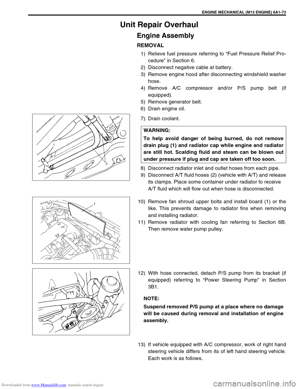
9) Disconnect A/T fluid hoses (2) (vehicle with A/T) and release
its clamps. Place some container under radiator to receive
A/T fluid which will flow out when hose is disconnected.
10) Remove fan shroud upper bolts and install board (1) or the
like. This prevents damage to radiator fins when removing
and installing radiator.
11) Remove radiator with cooling fan referring to Section 6B.
Then remove water pump pulley.
12) With hose connected, detach P/S pump from its bracket (if
equipped) referring to “Power Steering Pump” in Section
3B1.
13) If vehicle equipped with A/C compressor, work of right hand
steering vehicle differs from its of left hand steering vehicle.
Each work is as follows. WARNING:
To help avoid danger of being burned, do not remove
drain plug (1) and radiator cap while engine and radiator
are still hot. Scalding fluid and steam can be blown out
under pressure if plug and cap are taken off too soon.
NOTE:
Suspend removed P/S pump at a place where no damage
will be caused during removal and installation of engine
assembly.
Page 596 of 687

Downloaded from www.Manualslib.com manuals search engine ENGINE FUEL 6C-1
6F1
7A
7A1
7A
7A
7A1
7B1
7C1
7D
7E
7F
8A
8B
8C
6G
6C
6K
9
10
10A
10B
SECTION 6C
ENGINE FUEL
CONTENTS
General Description ....................................... 6C-2
Fuel System ................................................. 6C-2
Fuel Tank ..................................................... 6C-2
Fuel Pump Assembly ................................... 6C-3
Fuel Filler Cap .............................................. 6C-3
On-Vehicle Service......................................... 6C-4Fuel Lines .................................................... 6C-4
Fuel Filler Cap.............................................. 6C-4
Fuel Tank ..................................................... 6C-4
Fuel Pump Assembly ................................... 6C-7
Tightening Torque Specification ................ 6C-10
Special Tool .................................................. 6C-10
CAUTION:
For vehicles with a catalytic converter, be sure to use unleaded fuel only. Use of leaded and/or low
lead fuel can result in engine damage and reduce the effectiveness of the emission control system.
Page 597 of 687
Downloaded from www.Manualslib.com manuals search engine 6C-2 ENGINE FUEL
General Description
Fuel System
The main components of the fuel system are fuel tank, fuel pump assembly with fuel filter and fuel level gauge
and fuel cut valve, fuel feed line, fuel return line and fuel vapor line.
For the details of fuel flow and fuel vapor flow, refer to “Fuel Delivery System” and “Emission Control System” in
Section 6E.
Fuel Tank
The fuel tank is located under the rear section of the vehicle. The
fuel pump assembly is installed in fuel tank. Whenever servicing
the fuel pump assembly, the fuel tank must be removed from the
vehicle.
1. Fuel tank 4. Fuel filler cap 7. Fuel vapor line 10. Fuel filler hose clamp
2. Fuel pump assembly 5. Fuel feed line 8. Fuel filler neck Tightening torque
3. Breather hose 6. Fuel return line 9. Fuel tank mounting bolt
Page 598 of 687

Downloaded from www.Manualslib.com manuals search engine ENGINE FUEL 6C-3
Fuel Pump Assembly
The fuel pump assembly (1) consists of fuel pump (6), fuel filter
(2), fuel level gauge (5) and fuel cut valve (4).
FUEL PUMP
For structure and operation of the fuel pump, refer to “Fuel Deliv-
ery System” in Section 6E.
FUEL CUT VALVE
The fuel cut valve consists of a float and a spring. It allows only
the fuel vapor to flow into the canister and prevents the fuel from
flowing into the canister.
Fuel Filler Cap
The fuel tank filler neck has a vacuum cap.
A ratchet tightening device on the threaded fuel filler cap reduces
the chances of incorrect installation, which would prevent sealing
fuel vapors.
After the gasket (2) on fuel filler cap and the filler neck flange con-
tact, the ratchet produces a loud clicking noise, indicating the seal
has been set.
This cap has a vacuum relief valve (1) inside.
The vacuum relief valve opens to relieve the vacuum created in
the fuel tank.
3. Suction filter
Page 599 of 687

Downloaded from www.Manualslib.com manuals search engine 6C-4 ENGINE FUEL
On-Vehicle Service
Before work, refer to “Precaution on Fuel System Service” in Sec-
tion 6.
Fuel Lines
Due to the fact that fuel feed line is under high pressure, use spe-
cial care when servicing it.
INSPECTION
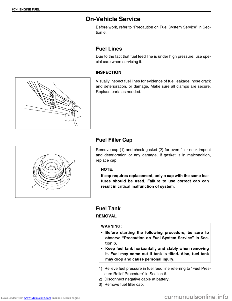
Visually inspect fuel lines for evidence of fuel leakage, hose crack
and deterioration, or damage. Make sure all clamps are secure.
Replace parts as needed.
Fuel Filler Cap
Remove cap (1) and check gasket (2) for even filler neck imprint
and deterioration or any damage. If gasket is in malcondition,
replace cap.
Fuel Tank
REMOVAL
1) Relieve fuel pressure in fuel feed line referring to “Fuel Pres-
sure Relief Procedure” in Section 6.
2) Disconnect negative cable at battery.
3) Remove fuel filler cap.
NOTE:
If cap requires replacement, only a cap with the same fea-
tures should be used. Failure to use correct cap can
result in critical malfunction of system.
WARNING:
Before starting the following procedure, be sure to
observe “Precaution on Fuel System Service” in Sec-
tion 6.
Keep fuel tank horizontally and stably when removing
it. Fuel may come out if tank is tilted. Also, fuel tank
may drop and cause personal injury.
Page 628 of 687

Downloaded from www.Manualslib.com manuals search engine ENGINE AND EMISSION CONTROL SYSTEM 6E-23
6) Start engine and warm it up to normal operating tempera-
ture.
7) Measure fuel pressure at idling.
If measured pressure doesn’t satisfy specification, refer to
“Diagnostic Flow Table B-3” in Section 6 and check each
possibly defective part. Replace if found defective.
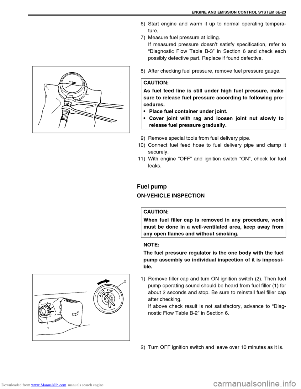
8) After checking fuel pressure, remove fuel pressure gauge.
9) Remove special tools from fuel delivery pipe.
10) Connect fuel feed hose to fuel delivery pipe and clamp it
securely.
11) With engine “OFF” and ignition switch “ON”, check for fuel
leaks.
Fuel pump
ON-VEHICLE INSPECTION
1) Remove filler cap and turn ON ignition switch (2). Then fuel
pump operating sound should be heard from fuel filler (1) for
about 2 seconds and stop. Be sure to reinstall fuel filler cap
after checking.
If above check result is not satisfactory, advance to “Diag-
nostic Flow Table B-2” in Section 6.
2) Turn OFF ignition switch and leave over 10 minutes as it is.CAUTION:
As fuel feed line is still under high fuel pressure, make
sure to release fuel pressure according to following pro-
cedures.
Place fuel container under joint.
Cover joint with rag and loosen joint nut slowly to
release fuel pressure gradually.
CAUTION:
When fuel filler cap is removed in any procedure, work
must be done in a well-ventilated area, keep away from
any open flames and without smoking.
NOTE:
The fuel pressure regulator is the one body with the fuel
pump assembly so individual inspection of it is impossi-
ble.