2005 SUZUKI JIMNY fuel
[x] Cancel search: fuelPage 35 of 687

Downloaded from www.Manualslib.com manuals search engine 0B-4 MAINTENANCE AND LUBRICATION
Maintenance Recommended Under Severe Driving Conditions
If the vehicle is usually used under the conditions corresponding to any severe condition code given below, it is
recommended that applicable maintenance operation be performed at the particular interval as shown in the fol-
lowing table.
Severe condition code
A : Repeated short trips
B : Driving on rough and/or muddy roads
C : Driving on dusty roads
D : Driving in extremely cold weather and/or salted roads
E : Repeated short trips in extremely cold weather
F : Leaded fuel use
G : – – – – –
H : Trailer towing (if admitted)
Severe
Condition CodeMaintenanceMaintenance
OperationMaintenance Interval
– B C D – – – –Drive belt (V-rib belt)IEvery 15,000 km
(9,000 miles) or 12 months
REvery 45,000 km
(27,000 miles) or 36 months
A – C D E F – H Engine oil and oil filter R Every 5,000 km (3,000 miles) or 4 months
– B – – – – – –Exhaust pipe mountings IEvery 15,000 km
(9,000 miles) or 12 months
– – C – – – – –Air cleaner filter ✱1I Every 2,500 km (1,500 miles)
REvery 30,000 km
(18,000 miles) or 24 months
A B C – E F – H Spark plugsNickel spark plug R Every 10,000 km (6,000 miles) or 8 months
Iridium spark plug
REvery 30,000 km
(18,000 miles) or 24 months
– B C D – – – H Wheel bearing IEvery 15,000 km
(9,000 miles) or 12 months
– B – – – – – –Suspension bolts and nuts TEvery 15,000 km
(9,000 miles) or 12 months
– B – D E – – H Propeller shafts IEvery 15,000 km
(9,000 miles) or 12 months
– B – – E – – HManual transmission,
transfer and differential oilRFirst time only:
15,000 km (9,000 miles) or 12 months
Second time and after: Every 30,000 km
(18,000 miles) or 24 months reckoning from
0 km (0 mile) or 0 month
– B – – E – – H Automatic transmission fluid REvery 30,000 km
(18,000 miles) or 24 months
– B C D – – – –Steering knuckle seal IEvery 15,000 km
(9,000 miles) or 12 months
NOTE:
“I”: Inspect and correct, replace or lubricate if necessary
“R”: Replace or change
“T”: Tighten to the specified torque
✱
✱✱ ✱1: Inspect or replace more frequently if necessary
Page 40 of 687

Downloaded from www.Manualslib.com manuals search engine MAINTENANCE AND LUBRICATION 0B-9
When carrying out periodic maintenance, or the vehicle is raised
for other service, check exhaust system as follows:
Check rubber mountings for damage, deterioration, and out
of position.
Check exhaust system for leakage, loose connections, dents
and damages.
If bolts or nuts are loose, tighten them to specification.
Check nearby body areas for damaged, missing, or misposi-
tioned parts, open seams, holes, loose connections or other
defects which could permit exhaust fumes to seep into the
vehicle.
Make sure that exhaust system components have enough
clearance from the underbody to avoid overheating and pos-
sible damage to the floor carpet.
Any defects should be fixed at once.
Ignition System
Spark Plugs
REPLACEMENT
Replace spark plugs with new ones referring to “Spark Plug” in
Section 6F.
Fuel System
Air Cleaner Filter
INSPECTION
1) Remove air cleaner case clamps (1).
2) Take cleaner filter out of air cleaner case.
3) Check air cleaner filter for dirt. Replace excessively dirty fil-
ter.
4) Blow off dust by compressed air from air outlet side of filter.
5) Install air cleaner filter into case.
6) Install air cleaner case cap and clamp it securely.
Page 41 of 687

Downloaded from www.Manualslib.com manuals search engine 0B-10 MAINTENANCE AND LUBRICATION
REPLACEMENT
Replace air cleaner filter with new one according to steps 1), 2)
and 5), 6) of inspection procedure.
Fuel Lines and Connections
INSPECTION
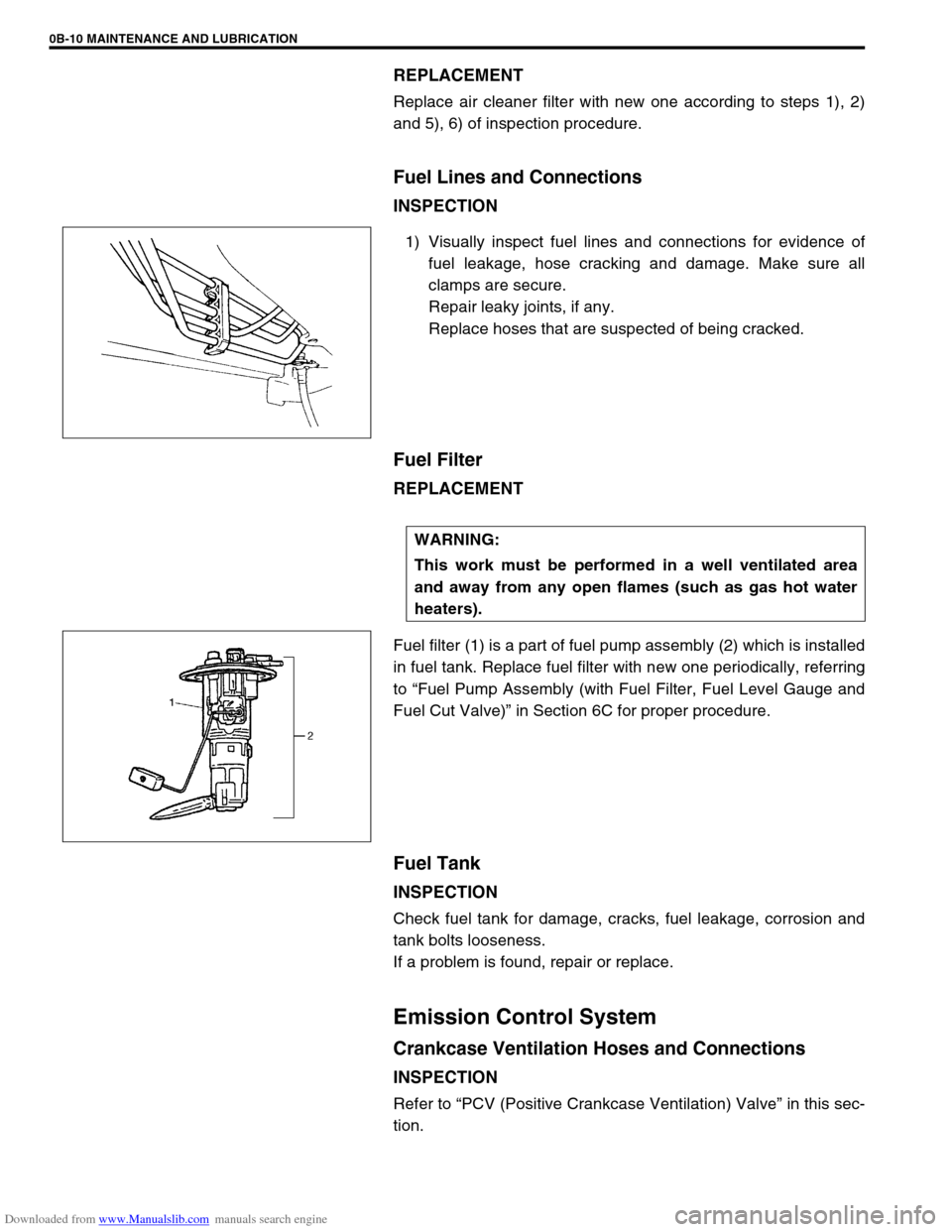
1) Visually inspect fuel lines and connections for evidence of
fuel leakage, hose cracking and damage. Make sure all
clamps are secure.
Repair leaky joints, if any.
Replace hoses that are suspected of being cracked.
Fuel Filter
REPLACEMENT
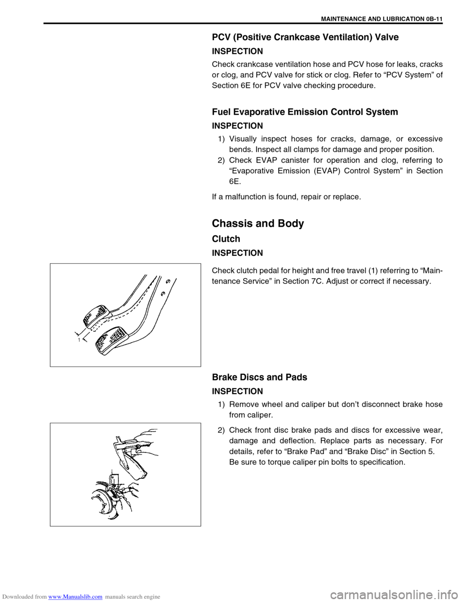
Fuel filter (1) is a part of fuel pump assembly (2) which is installed
in fuel tank. Replace fuel filter with new one periodically, referring
to “Fuel Pump Assembly (with Fuel Filter, Fuel Level Gauge and
Fuel Cut Valve)” in Section 6C for proper procedure.
Fuel Tank
INSPECTION
Check fuel tank for damage, cracks, fuel leakage, corrosion and
tank bolts looseness.
If a problem is found, repair or replace.
Emission Control System
Crankcase Ventilation Hoses and Connections
INSPECTION
Refer to “PCV (Positive Crankcase Ventilation) Valve” in this sec-
tion.
WARNING:
This work must be performed in a well ventilated area
and away from any open flames (such as gas hot water
heaters).
Page 42 of 687

Downloaded from www.Manualslib.com manuals search engine MAINTENANCE AND LUBRICATION 0B-11
PCV (Positive Crankcase Ventilation) Valve
INSPECTION
Check crankcase ventilation hose and PCV hose for leaks, cracks
or clog, and PCV valve for stick or clog. Refer to “PCV System” of
Section 6E for PCV valve checking procedure.
Fuel Evaporative Emission Control System
INSPECTION
1) Visually inspect hoses for cracks, damage, or excessive
bends. Inspect all clamps for damage and proper position.
2) Check EVAP canister for operation and clog, referring to
“Evaporative Emission (EVAP) Control System” in Section
6E.
If a malfunction is found, repair or replace.
Chassis and Body
Clutch
INSPECTION
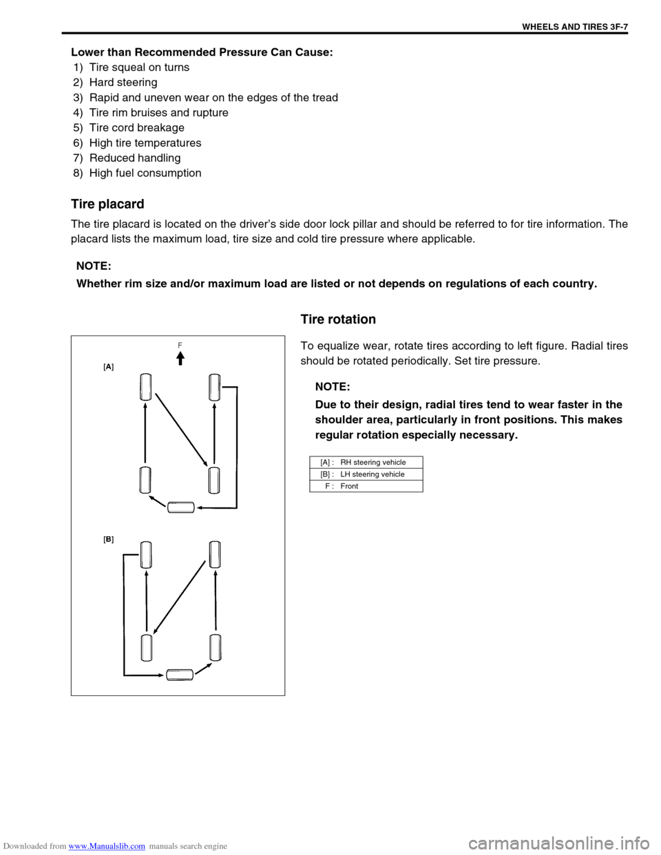
Check clutch pedal for height and free travel (1) referring to “Main-
tenance Service” in Section 7C. Adjust or correct if necessary.
Brake Discs and Pads
INSPECTION
1) Remove wheel and caliper but don’t disconnect brake hose
from caliper.
2) Check front disc brake pads and discs for excessive wear,
damage and deflection. Replace parts as necessary. For
details, refer to “Brake Pad” and “Brake Disc” in Section 5.
Be sure to torque caliper pin bolts to specification.
Page 52 of 687

Downloaded from www.Manualslib.com manuals search engine MAINTENANCE AND LUBRICATION 0B-21
GEARSHIFT OR SELECTOR LEVER (TRANSMISSION)
Check gear shift or selector lever for smooth shifting to all positions and for good performance of transmission in
any position.
With automatic transmission equipped vehicle, also check that shift indicator indicates properly according to
which position selector lever is shifted to.
With automatic transmission equipped vehicle, make sure that vehicle is at complete stop when shifting selector
lever to “P” range position and release all brakes.
BRAKE
Foot Brake
Check the following:
that brake pedal has proper travel,
that brake works properly,
that it is free from noise,
that braking force is applied equally on all wheels,
and that brake do not drag.
Parking Brake
Check that lever has proper travel.
Check to ensure that parking brake is fully effective when the vehicle is stopped on the safe slope and brake
lever is pulled all the way.
STEERING
Check to ensure that steering wheel is free from instability, or abnormally heavy feeling.
Check that the vehicle does not wander or pull to one side.
ENGINE
Check that engine responds readily at all speeds.
Check that engine is free from abnormal noise and abnormal vibration.
BODY, WHEELS AND POWER TRANSMITTING SYSTEM
Check that body, wheels and power transmitting system are free from abnormal noise and abnormal vibration or
any other abnormal condition.
METERS AND GAUGE
Check that speedometer, odometer, fuel meter, temperature gauge, etc. are operating accurately.
LIGHTS
Check that all lights operate properly.
WINDSHIELD DEFROSTER
Periodically check that air comes out from defroster outlet when operating heater or air conditioning.
Set mode control lever to defroster position and fan switch lever to “HI” position for this check. WARNING:
With vehicle parked on a fairly steep slope, make sure nothing is in the way downhill to avoid any per-
sonal injury or property damage. Be prepared to apply regular brake quickly even if vehicle should
start to move.
Page 250 of 687

Downloaded from www.Manualslib.com manuals search engine WHEELS AND TIRES 3F-7
Lower than Recommended Pressure Can Cause:
1) Tire squeal on turns
2) Hard steering
3) Rapid and uneven wear on the edges of the tread
4) Tire rim bruises and rupture
5) Tire cord breakage
6) High tire temperatures
7) Reduced handling
8) High fuel consumption
Tire placard
The tire placard is located on the driver’s side door lock pillar and should be referred to for tire information. The
placard lists the maximum load, tire size and cold tire pressure where applicable.
Tire rotation
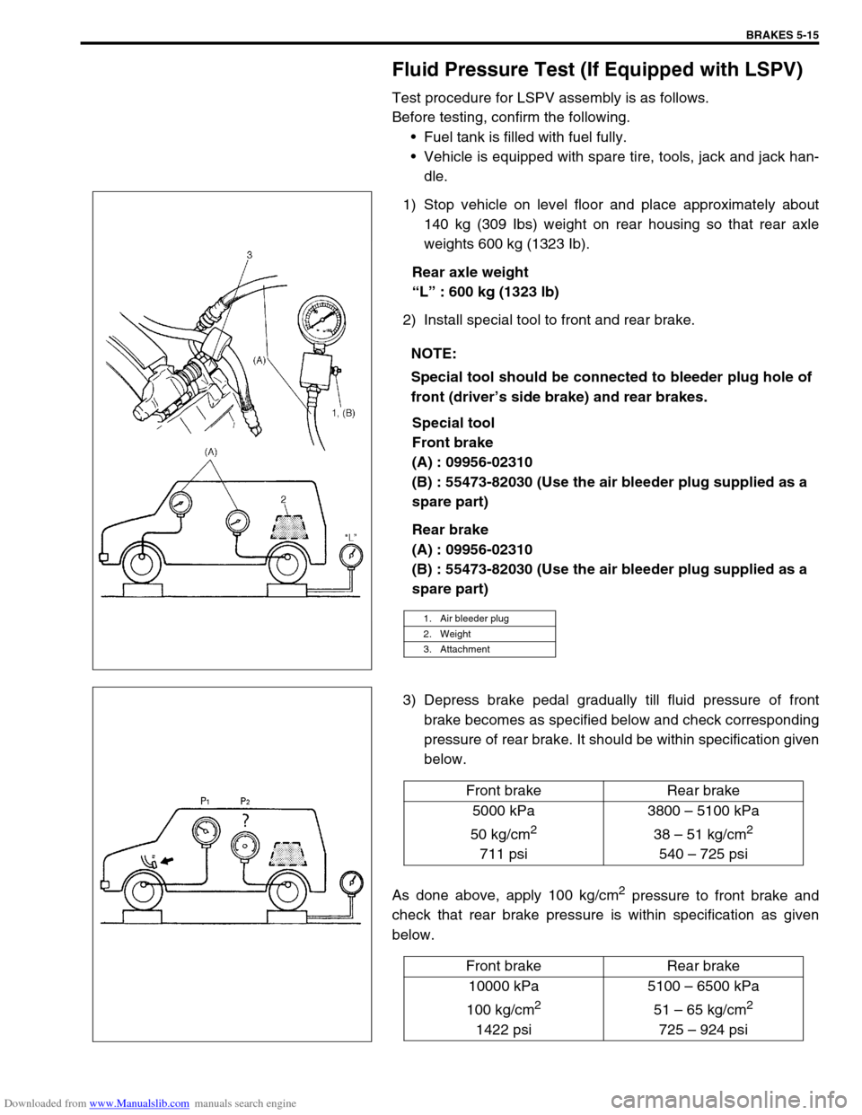
To equalize wear, rotate tires according to left figure. Radial tires
should be rotated periodically. Set tire pressure. NOTE:
Whether rim size and/or maximum load are listed or not depends on regulations of each country.
NOTE:
Due to their design, radial tires tend to wear faster in the
shoulder area, particularly in front positions. This makes
regular rotation especially necessary.
[A] : RH steering vehicle
[B] : LH steering vehicle
F : Front
Page 276 of 687

Downloaded from www.Manualslib.com manuals search engine BRAKES 5-15
Fluid Pressure Test (If Equipped with LSPV)
Test procedure for LSPV assembly is as follows.
Before testing, confirm the following.
Fuel tank is filled with fuel fully.
Vehicle is equipped with spare tire, tools, jack and jack han-
dle.
1) Stop vehicle on level floor and place approximately about
140 kg (309 Ibs) weight on rear housing so that rear axle
weights 600 kg (1323 Ib).
Rear axle weight
“L” : 600 kg (1323 lb)
2) Install special tool to front and rear brake.
Special tool
Front brake
(A) : 09956-02310
(B) : 55473-82030 (Use the air bleeder plug supplied as a
spare part)
Rear brake
(A) : 09956-02310
(B) : 55473-82030 (Use the air bleeder plug supplied as a
spare part)
3) Depress brake pedal gradually till fluid pressure of front
brake becomes as specified below and check corresponding
pressure of rear brake. It should be within specification given
below.
As done above, apply 100 kg/cm
2 pressure to front brake and
check that rear brake pressure is within specification as given
below.NOTE:
Special tool should be connected to bleeder plug hole of
front (driver’s side brake) and rear brakes.
1. Air bleeder plug
2. Weight
3. Attachment
Front brake Rear brake
5000 kPa
50 kg/cm
2
711 psi3800 – 5100 kPa
38 – 51 kg/cm
2
540 – 725 psi
Front brake Rear brake
10000 kPa
100 kg/cm
2
1422 psi5100 – 6500 kPa
51 – 65 kg/cm
2
725 – 924 psi
Page 304 of 687

Downloaded from www.Manualslib.com manuals search engine BRAKES 5-43
LSPV Assembly
INSPECTION AND ADJUSTMENT
1) Confirm the following before inspection and adjustment.
Fuel tank is filled with fuel fully.
Vehicle is equipped with spare tire, tools, jack and jack han-
dle.
Vehicle is free from any other load.
Place it on level floor.
2) Push up LSPV lever with finger till it stops and measure
length of coil spring (“a” in figure).
3) Spring length “a” should be as specified.
Spring length “a”
147 mm (5.79 in.)
4) If it isn’t, adjust it to specification by changing stay position
as shown in figure. After adjustment, tighten bolt to specified
torque.
Tightening torque
LSPV adjust bolt
(a) : 25 N·m (2.5 kg-m, 18.0 lb-ft)
NOTE:
Check to make sure that LSPV body and brake pipe joints
are free from fluid leakage. Replace defective parts, if
any.