2005 SUZUKI JIMNY ATE
[x] Cancel search: ATEPage 12 of 687

Downloaded from www.Manualslib.com manuals search engine GENERAL INFORMATION 0A-7
General Precautions
The WARNING and CAUTION below describe some general precautions that you should observe when servic-
ing a vehicle. These general precautions apply to many of the service procedures described in this manual, and
they will not necessarily be repeated with each procedure to which they apply.
Before starting any service work, cover fenders, seats
and any other parts that are likely to get scratched or
stained during servicing. Also, be aware that what you
wear (e.g, buttons) may cause damage to the vehicle’s
finish.
When performing service to electrical parts that does
not require use of battery power, disconnect the nega-
tive cable of the battery. WARNING:
Whenever raising a vehicle for service, be sure to follow the instructions under “Vehicle Lifting
Points” in this section.
When it is necessary to do service work with the engine running, make sure that the parking brake
is set fully and the transmission is in Neutral (for manual transmission vehicles) or Park (for auto-
matic transmission vehicles), Keep hands, hair, clothing, tools, etc. away from the fan and belts
when the engine is running.
When it is necessary to run the engine indoors, make sure that the exhaust gas is forced outdoors.
Do not perform service work in areas where combustible materials can come in contact with a hot
exhaust system. When working with toxic or flammable materials (such as gasoline and refriger-
ant), make sure that the area you work in is well-ventilated.
To avoid getting burned, keep away from hot metal parts such as the radiator, exhaust manifold,
tailpipe, muffler, etc.
New and used engine oil can be hazardous. Children and pets may be harmed by swallowing new or
used oil. Keep new and used oil and used engine oil filters away from children and pets.
Continuous contact with used engine oil has been found to cause [skin] cancer in laboratory ani-
mals. Brief contact with used oil may irritate skin. To minimize your exposure to used engine oil,
wear a long-sleeve shirt and moisture-proof gloves (such as dish washing gloves) when changing
engine oil. If engine oil contacts your skin, wash thoroughly with soap and water. Launder any
clothing or rags if wet with oil, recycle or properly dispose of used oil and filters.
Make sure the bonnet is fully closed and latched before driving. If it is not, it can fly up unexpectedly
during driving, obstructing your view and resulting in an accident.
Page 13 of 687

Downloaded from www.Manualslib.com manuals search engine 0A-8 GENERAL INFORMATION
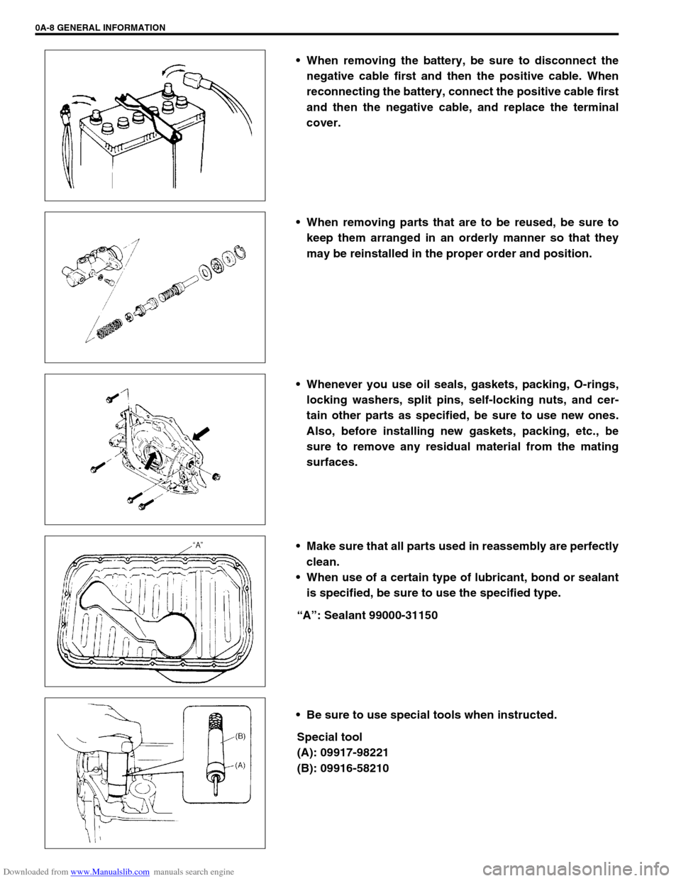
When removing the battery, be sure to disconnect the
negative cable first and then the positive cable. When
reconnecting the battery, connect the positive cable first
and then the negative cable, and replace the terminal
cover.
When removing parts that are to be reused, be sure to
keep them arranged in an orderly manner so that they
may be reinstalled in the proper order and position.
Whenever you use oil seals, gaskets, packing, O-rings,
locking washers, split pins, self-locking nuts, and cer-
tain other parts as specified, be sure to use new ones.
Also, before installing new gaskets, packing, etc., be
sure to remove any residual material from the mating
surfaces.
Make sure that all parts used in reassembly are perfectly
clean.
When use of a certain type of lubricant, bond or sealant
is specified, be sure to use the specified type.
“A”: Sealant 99000-31150
Be sure to use special tools when instructed.
Special tool
(A): 09917-98221
(B): 09916-58210
Page 14 of 687

Downloaded from www.Manualslib.com manuals search engine GENERAL INFORMATION 0A-9
When disconnecting vacuum hoses, attach a tag
describing the correct installation positions so that the
hoses can be reinstalled correctly.
After servicing fuel, oil, coolant, vacuum, exhaust or
brake systems, check all lines related to the system for
leaks.
For vehicles equipped with fuel injection systems, never
disconnect the fuel line between the fuel pump and
injector without first releasing the fuel pressure, or fuel
can be sprayed out under pressure.
When performing a work that produces a heat exceeding
80°C (176°F) in the vicinity of the electrical parts, remove
the heat sensitive electrical part(s) beforehand.
Use care not to expose connectors and electrical parts
to water which will be a cause of a trouble.
Always be careful not to handle electrical parts (com-
puter, relay, etc.) in a rough manner or drop them.
Page 17 of 687

Downloaded from www.Manualslib.com manuals search engine 0A-12 GENERAL INFORMATION
Never connect any tester (voltmeter, ohmmeter, or what-
ever) to electronic control unit when its coupler is dis-
connected. Attempt to do it may cause damage to it.
Never connect an ohmmeter to electronic control unit
with its coupler connected to it. Attempt to do it may
cause damage to electronic control unit and sensors.
Be sure to use a specified voltmeter / ohmmeter. Other-
wise, accurate measurements may not be obtained or
personal injury may result.
When taking measurements at electrical connectors
using a tester probe (2), be sure to insert the probe from
the wire harness side (backside) of the connector (1).
When connecting meter probe (2) from terminal side of
coupler (1) because it can’t be connected from harness
side, use extra care not to bend male terminal of coupler
of force its female terminal open for connection.
In case of such coupler as shown connect probe as
shown to avoid opening female terminal.
Never connect probe where male terminal is supposed
to fit.
When checking connection of terminals, check its male
half for bend and female half for excessive opening and
both for locking (looseness), corrosion, dust, etc.
Before measuring voltage to check for electrical system,
check to make sure that battery voltage is 11V or higher.
Such terminal voltage check at low battery voltage will
lead to erroneous diagnosis.
Page 18 of 687

Downloaded from www.Manualslib.com manuals search engine GENERAL INFORMATION 0A-13
Electrical Circuit Inspection Procedure
While there are various electrical circuit inspection methods,
described here is a general method to check its open and short
circuit by using an ohmmeter and a voltmeter.
Open circuit check
Possible causes for the open circuit are as follows. As the cause
is in the connector or terminal in many cases, they need to be
checked particularly carefully.
Loose connection of connector
Poor contact of terminal (due to dirt, corrosion or rust on it,
poor contact tension, entry of foreign object etc.)
Wire harness being open
When checking system circuits including an electronic control unit
such as ECM, TCM, ABS control module, etc., it is important to
perform careful check, starting with items which are easier to
check.
1) Disconnect negative cable from battery
2) Check each connector at both ends of the circuit being
checked for loose connection. Also check lock condition of
connector if equipped with connector lock.
3) Using a test male terminal, check both terminals of the circuit
being checked for contact tension of its female terminal.
Check each terminal visually for poor contact (possibly
caused by dirt, corrosion, rust entry of foreign object, etc.).
At the same time, check to make sure that each terminal is
locked in the connector fully.
4) Using the following continuity check or voltage check proce-
dure, check the wire harness for open circuit and poor con-
nection with its terminals. Locate abnormality, if any.
1. Check contact tension by inserting and removing just for once
1. Looseness of crimping
2. Open
3. Thin wire (single strand of wire)
Page 19 of 687

Downloaded from www.Manualslib.com manuals search engine 0A-14 GENERAL INFORMATION
CONTINUITY CHECK
1) Measure resistance between connector terminals at both
ends of the circuit being checked (between A-1 and C-1 in
the figure).
If no continuity is indicated (infinity or over limit), that means
that the circuit is open between terminals A-1 and C-1.
2) Disconnect the connector included in the circuit (connector-B
in the figure) and measure resistance between terminals A-1
and B-1.
If no continuity is indicated, that means that the circuit is
open between terminals A-1 and B-1. If continuity is indi-
cated, there is an open circuit between terminals B-1 and C-
1 or an abnormality in connector-B.
VOLTAGE CHECK
If voltage is supplied to the circuit being checked, voltage check
can be used as circuit check.
1) With all connectors connected and voltage applied to the cir-
cuit being checked, measure voltage between each terminal
and body ground.
a) If measurements were taken as shown in the figure at the
left and results were as listed below, it means that the cir-
cuit is open between terminals B-1 and A-1.
Voltage Between
C-1 and body ground: Approx. 5V
B-1 and body ground: Approx. 5V
A-1 and body ground: 0V
b) Also, if measured values were as listed below, it means that
there is a resistance (abnormality) of such level that corre-
sponds to the voltage drop in the circuit between terminals
A-1 and B-1.
Voltage Between
C-1 and body ground: Approx. 5V
B-1 and body ground: Approx. 5V
A-1 and body ground: Approx. 3V (2V voltage drop)
Page 20 of 687

Downloaded from www.Manualslib.com manuals search engine GENERAL INFORMATION 0A-15
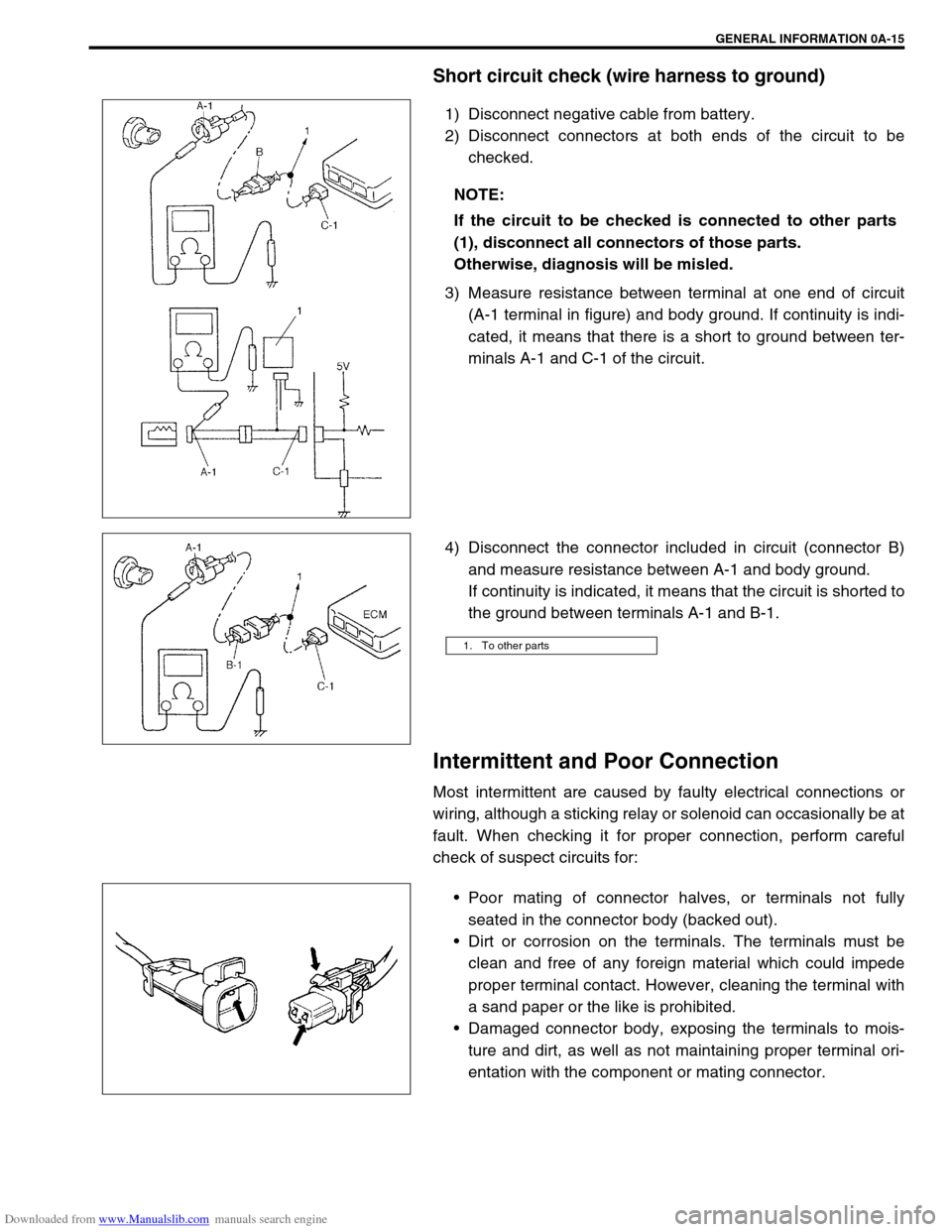
Short circuit check (wire harness to ground)
1) Disconnect negative cable from battery.
2) Disconnect connectors at both ends of the circuit to be
checked.
3) Measure resistance between terminal at one end of circuit
(A-1 terminal in figure) and body ground. If continuity is indi-
cated, it means that there is a short to ground between ter-
minals A-1 and C-1 of the circuit.
4) Disconnect the connector included in circuit (connector B)
and measure resistance between A-1 and body ground.
If continuity is indicated, it means that the circuit is shorted to
the ground between terminals A-1 and B-1.
Intermittent and Poor Connection
Most intermittent are caused by faulty electrical connections or
wiring, although a sticking relay or solenoid can occasionally be at
fault. When checking it for proper connection, perform careful
check of suspect circuits for:
Poor mating of connector halves, or terminals not fully
seated in the connector body (backed out).
Dirt or corrosion on the terminals. The terminals must be
clean and free of any foreign material which could impede
proper terminal contact. However, cleaning the terminal with
a sand paper or the like is prohibited.
Damaged connector body, exposing the terminals to mois-
ture and dirt, as well as not maintaining proper terminal ori-
entation with the component or mating connector. NOTE:
If the circuit to be checked is connected to other parts
(1), disconnect all connectors of those parts.
Otherwise, diagnosis will be misled.
1. To other parts
Page 22 of 687

Downloaded from www.Manualslib.com manuals search engine GENERAL INFORMATION 0A-17
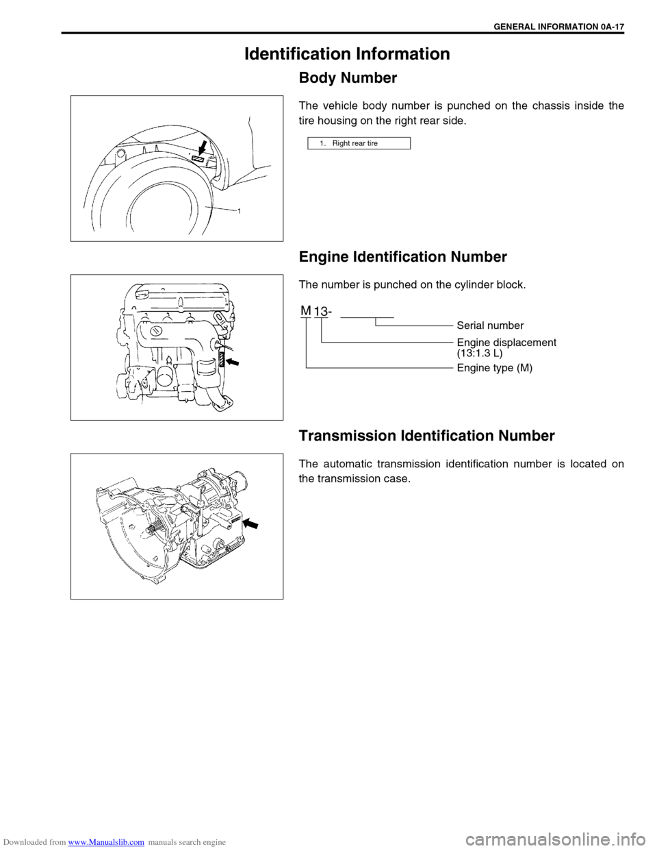
Identification Information
Body Number
The vehicle body number is punched on the chassis inside the
tire housing on the right rear side.
Engine Identification Number
The number is punched on the cylinder block.
Transmission Identification Number
The automatic transmission identification number is located on
the transmission case.
1. Right rear tire
M
13-
Serial number
Engine displacement
(13:1.3 L)
Engine type (M)