Page 495 of 687
Downloaded from www.Manualslib.com manuals search engine 6A1-14 ENGINE MECHANICAL (M13 ENGINE)
Air Cleaner Assembly
REMOVAL
1) Disconnect negative cable at battery.
2) Disconnect IAT sensor coupler (1).
3) Disconnect breather hose from air cleaner outlet No.2 hose
(2).
4) Remove air cleaner outlet No.2 hose fastening bolt (3).
5) Loosen air cleaner outlet No.2 hose clamp bolt (4).
6) Remove air cleaner case fastening bolts (5).
7) Remove air cleaner assembly with outlet hoses.
INSTALLATION
Reverse removal procedure for installation.
Knock Sensor
REMOVAL
1) Disconnect negative cable at battery.
2) Remove intake manifold referring to “Throttle Body and
Intake Manifold” in this section.
3) Disconnect knock sensor connector (1).
4) Remove knock sensor (2) from cylinder block.
INSPECTION
Check sensor for damage.
If any faulty is found, replace.
INSTALLATION
Reverse removal procedure for installation.
Tightening torque
Knock sensor (a) : 23 N·m (2.3 kg-m, 16.5 lb-ft)
Page 506 of 687
Downloaded from www.Manualslib.com manuals search engine ENGINE MECHANICAL (M13 ENGINE) 6A1-25
4) Drain engine oil by removing drain plug.
5) Remove clutch housing (torque converter housing for A/T
vehicle) lower plate (1).
6) Remove oil pan and then oil pump strainer (1) from cylinder
block.
CLEAN
Inside of oil pan and oil pump strainer screen.
Clean sealing surface on oil pan and cylinder block.
Remove oil, old sealant and dust from sealing surface.
Page 507 of 687

Downloaded from www.Manualslib.com manuals search engine 6A1-26 ENGINE MECHANICAL (M13 ENGINE)
INSTALLATION
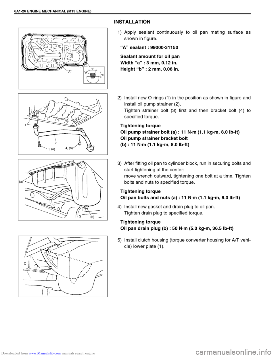
1) Apply sealant continuously to oil pan mating surface as
shown in figure.
“A” sealant : 99000-31150
Sealant amount for oil pan
Width “a” : 3 mm, 0.12 in.
Height “b” : 2 mm, 0.08 in.
2) Install new O-rings (1) in the position as shown in figure and
install oil pump strainer (2).
Tighten strainer bolt (3) first and then bracket bolt (4) to
specified torque.
Tightening torque
Oil pump strainer bolt (a) : 11 N·m (1.1 kg-m, 8.0 lb-ft)
Oil pump strainer bracket bolt
(b) : 11 N·m (1.1 kg-m, 8.0 lb-ft)
3) After fitting oil pan to cylinder block, run in securing bolts and
start tightening at the center:
move wrench outward, tightening one bolt at a time. Tighten
bolts and nuts to specified torque.
Tightening torque
Oil pan bolts and nuts (a) : 11 N·m (1.1 kg-m, 8.0 lb-ft)
4) Install new gasket and drain plug to oil pan.
Tighten drain plug to specified torque.
Tightening torque
Oil pan drain plug (b) : 50 N·m (5.0 kg-m, 36.5 lb-ft)
5) Install clutch housing (torque converter housing for A/T vehi-
cle) lower plate (1).
Page 511 of 687
Downloaded from www.Manualslib.com manuals search engine 6A1-30 ENGINE MECHANICAL (M13 ENGINE)
12) Remove crankshaft pulley bolt.
To lock crankshaft pulley (1), use special tool with it as
shown in figure.
Special tool
(A) : 09917-68221
13) Remove crankshaft pulley (1).
If it is hard to remove, use special tools as shown in figure.
If bolts of special tool are too long, replace them with those
of suitable length.
Special tool
(A) : 09944-36011
(B) : 09926-58010
14) Remove oil pan referring to “Oil Pan and Oil Pump Strainer”
in this section.
15) Remove cylinder head cover referring to “Cylinder Head
Cover” in this section.
16) Disconnect CMP sensor coupler (1) and release its harness
clamps.
17) Remove water outlet pipe (2).
18) Remove timing chain cover (3).
CLEANING
Clean sealing surface on timing chain cover, cylinder block
and cylinder head.
Remove oil, old sealant and dust from sealing surface.
Page 513 of 687

Downloaded from www.Manualslib.com manuals search engine 6A1-32 ENGINE MECHANICAL (M13 ENGINE)
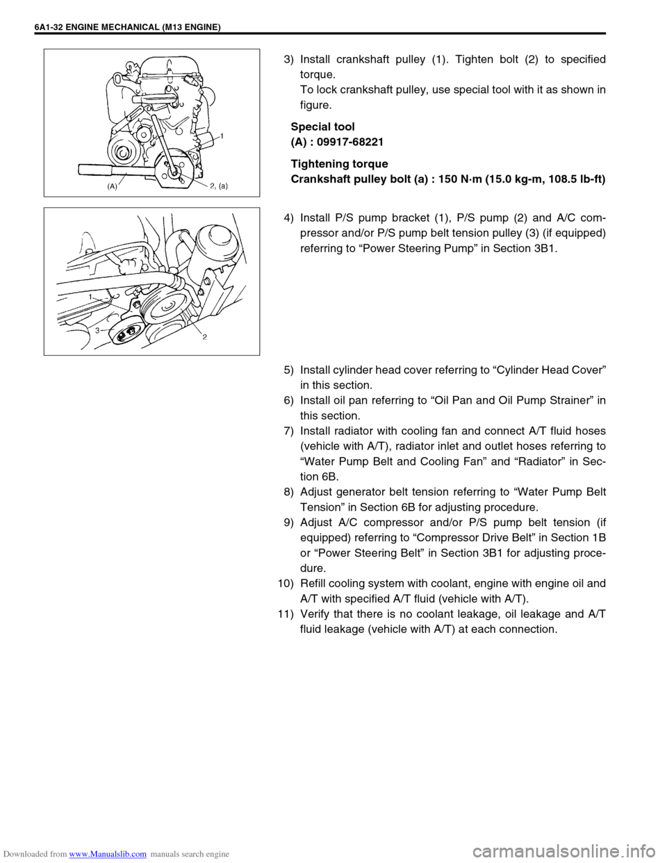
3) Install crankshaft pulley (1). Tighten bolt (2) to specified
torque.
To lock crankshaft pulley, use special tool with it as shown in
figure.
Special tool
(A) : 09917-68221
Tightening torque
Crankshaft pulley bolt (a) : 150 N·m (15.0 kg-m, 108.5 lb-ft)
4) Install P/S pump bracket (1), P/S pump (2) and A/C com-
pressor and/or P/S pump belt tension pulley (3) (if equipped)
referring to “Power Steering Pump” in Section 3B1.
5) Install cylinder head cover referring to “Cylinder Head Cover”
in this section.
6) Install oil pan referring to “Oil Pan and Oil Pump Strainer” in
this section.
7) Install radiator with cooling fan and connect A/T fluid hoses
(vehicle with A/T), radiator inlet and outlet hoses referring to
“Water Pump Belt and Cooling Fan” and “Radiator” in Sec-
tion 6B.
8) Adjust generator belt tension referring to “Water Pump Belt
Tension” in Section 6B for adjusting procedure.
9) Adjust A/C compressor and/or P/S pump belt tension (if
equipped) referring to “Compressor Drive Belt” in Section 1B
or “Power Steering Belt” in Section 3B1 for adjusting proce-
dure.
10) Refill cooling system with coolant, engine with engine oil and
A/T with specified A/T fluid (vehicle with A/T).
11) Verify that there is no coolant leakage, oil leakage and A/T
fluid leakage (vehicle with A/T) at each connection.
Page 522 of 687
Downloaded from www.Manualslib.com manuals search engine ENGINE MECHANICAL (M13 ENGINE) 6A1-41
10) Apply engine oil to timing chain and then turn crankshaft
clockwise by 2 revolutions and check that match marks (1)
on intake and exhaust camshaft timing sprockets are in
match with notches (2) on cylinder head and key (3) is on
upside of crankshaft as shown in figure.
If each mark of timing chain and each match mark are no
matches, adjust each sprocket and timing chain.
11) Install timing chain cover referring to “Timing Chain Cover” in
this section.
12) Perform Steps 3) to 8) of “INSTALLATION” of “Timing Chain
Cover” in this section.
21
1
3
Page 524 of 687
Downloaded from www.Manualslib.com manuals search engine ENGINE MECHANICAL (M13 ENGINE) 6A1-43
7) Remove tappets (1) with shims (2).
INSPECTION
Cam Wear
Using a micrometer, measure cam height “a”. If measured height
is below its limit, replace camshaft.
Cam height “a” of camshaft
Camshaft Runout
Set camshaft between two “V” blocks, and measure its runout by
using a dial gauge.
If measured runout exceeds below limit, replace camshaft.
Camshaft runout limit
0.10 mm (0.0039 in.)
Camshaft Journal Wear
Check camshaft journals and camshaft housings for pitting,
scratches, wear or damage.
If any malcondition is found, replace camshaft or cylinder head
with housing. Never replace cylinder head without replacing
housings.
Standard Limit
Intake cam 44.919 – 45.079 mm
(1.768 – 1.775 in.)44.80 mm
(1.764 in.)
Exhaust cam 44.399 – 44.559 mm
(1.748 – 1.754 in.)44.28 mm
(1.743 in.)
Page 535 of 687

Downloaded from www.Manualslib.com manuals search engine 6A1-54 ENGINE MECHANICAL (M13 ENGINE)
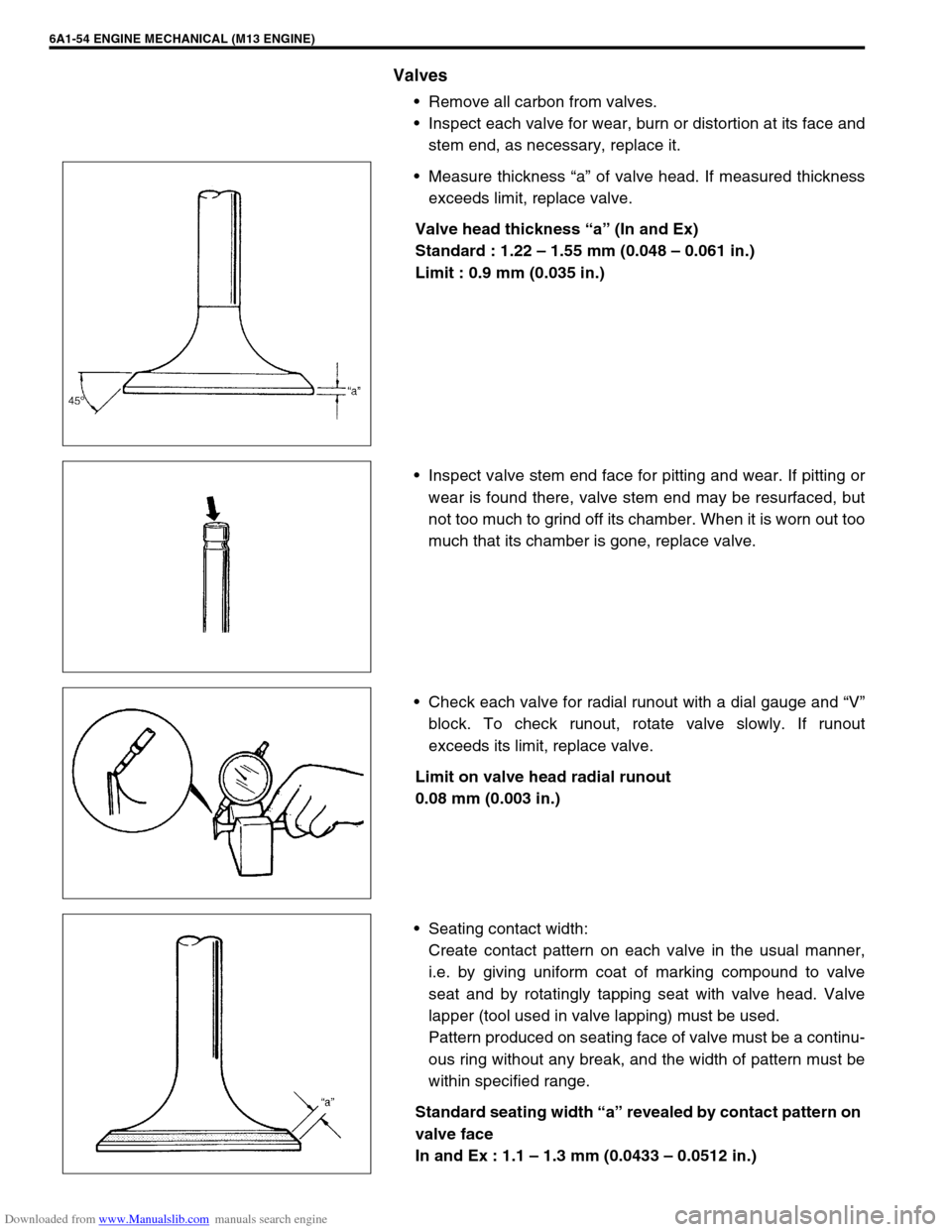
Valves
Remove all carbon from valves.
Inspect each valve for wear, burn or distortion at its face and
stem end, as necessary, replace it.
Measure thickness “a” of valve head. If measured thickness
exceeds limit, replace valve.
Valve head thickness “a” (In and Ex)
Standard : 1.22 – 1.55 mm (0.048 – 0.061 in.)
Limit : 0.9 mm (0.035 in.)
Inspect valve stem end face for pitting and wear. If pitting or
wear is found there, valve stem end may be resurfaced, but
not too much to grind off its chamber. When it is worn out too
much that its chamber is gone, replace valve.
Check each valve for radial runout with a dial gauge and “V”
block. To check runout, rotate valve slowly. If runout
exceeds its limit, replace valve.
Limit on valve head radial runout
0.08 mm (0.003 in.)
Seating contact width:
Create contact pattern on each valve in the usual manner,
i.e. by giving uniform coat of marking compound to valve
seat and by rotatingly tapping seat with valve head. Valve
lapper (tool used in valve lapping) must be used.
Pattern produced on seating face of valve must be a continu-
ous ring without any break, and the width of pattern must be
within specified range.
Standard seating width “a” revealed by contact pattern on
valve face
In and Ex : 1.1 – 1.3 mm (0.0433 – 0.0512 in.)