Page 540 of 687
Downloaded from www.Manualslib.com manuals search engine ENGINE MECHANICAL (M13 ENGINE) 6A1-59
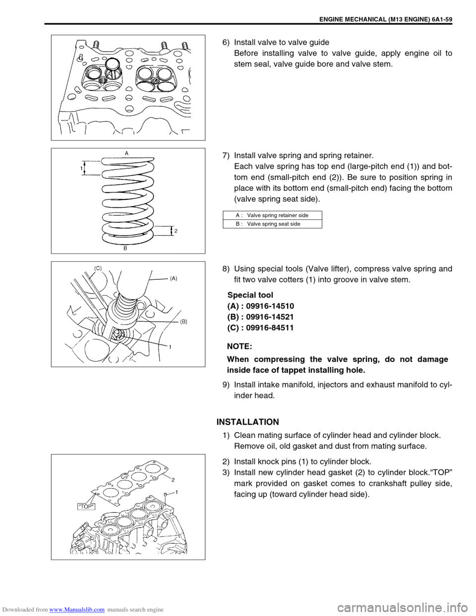
6) Install valve to valve guide
Before installing valve to valve guide, apply engine oil to
stem seal, valve guide bore and valve stem.
7) Install valve spring and spring retainer.
Each valve spring has top end (large-pitch end (1)) and bot-
tom end (small-pitch end (2)). Be sure to position spring in
place with its bottom end (small-pitch end) facing the bottom
(valve spring seat side).
8) Using special tools (Valve lifter), compress valve spring and
fit two valve cotters (1) into groove in valve stem.
Special tool
(A) : 09916-14510
(B) : 09916-14521
(C) : 09916-84511
9) Install intake manifold, injectors and exhaust manifold to cyl-
inder head.
INSTALLATION
1) Clean mating surface of cylinder head and cylinder block.
Remove oil, old gasket and dust from mating surface.
2) Install knock pins (1) to cylinder block.
3) Install new cylinder head gasket (2) to cylinder block.“TOP”
mark provided on gasket comes to crankshaft pulley side,
facing up (toward cylinder head side).
A : Valve spring retainer side
B : Valve spring seat side
NOTE:
When compressing the valve spring, do not damage
inside face of tappet installing hole.
Page 541 of 687
Downloaded from www.Manualslib.com manuals search engine 6A1-60 ENGINE MECHANICAL (M13 ENGINE)
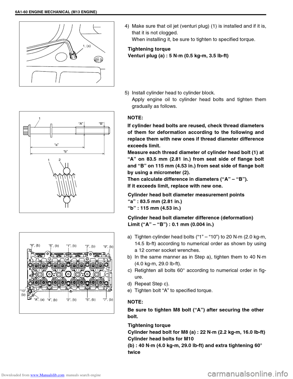
4) Make sure that oil jet (venturi plug) (1) is installed and if it is,
that it is not clogged.
When installing it, be sure to tighten to specified torque.
Tightening torque
Venturi plug (a) : 5 N·m (0.5 kg-m, 3.5 lb-ft)
5) Install cylinder head to cylinder block.
Apply engine oil to cylinder head bolts and tighten them
gradually as follows.
Cylinder head bolt diameter measurement points
“a” : 83.5 mm (2.81 in.)
“b” : 115 mm (4.53 in.)
Cylinder head bolt diameter difference (deformation)
Limit (“A” – “B”) : 0.1 mm (0.004 in.)
a) Tighten cylinder head bolts (“1” – “10”) to 20 N·m (2.0 kg-m,
14.5 lb-ft) according to numerical order as shown by using
a 12 corner socket wrenches.
b) In the same manner as in Step a), tighten them to 40 N·m
(4.0 kg-m, 29.0 lb-ft).
c) Retighten all bolts 60° according to numerical order in fig-
ure.
d) Repeat Step c).
e) Tighten bolt “A” to specified torque.
Tightening torque
Cylinder head bolt for M8 (a) : 22 N·m (2.2 kg-m, 16.0 lb-ft)
Cylinder head bolts for M10
(b) : 40 N·m (4.0 kg-m, 29.0 lb-ft) and extra tightening 60°
twice
NOTE:
If cylinder head bolts are reused, check thread diameters
of them for deformation according to the following and
replace them with new ones if thread diameter difference
exceeds limit.
Measure each thread diameter of cylinder head bolt (1) at
“A” on 83.5 mm (2.81 in.) from seat side of flange bolt
and “B” on 115 mm (4.53 in.) from seat side of flange bolt
by using a micrometer (2).
Then calculate difference in diameters (“A” – “B”).
If it exceeds limit, replace with new one.
“A”
“a”
“b”“B”
1
12
NOTE:
Be sure to tighten M8 bolt (“A”) after securing the other
bolt.
Page 551 of 687
Downloaded from www.Manualslib.com manuals search engine 6A1-70 ENGINE MECHANICAL (M13 ENGINE)
INSTALLATION
1) Apply engine oil to pistons, rings, cylinder walls, connecting
rod bearings and crankpins.
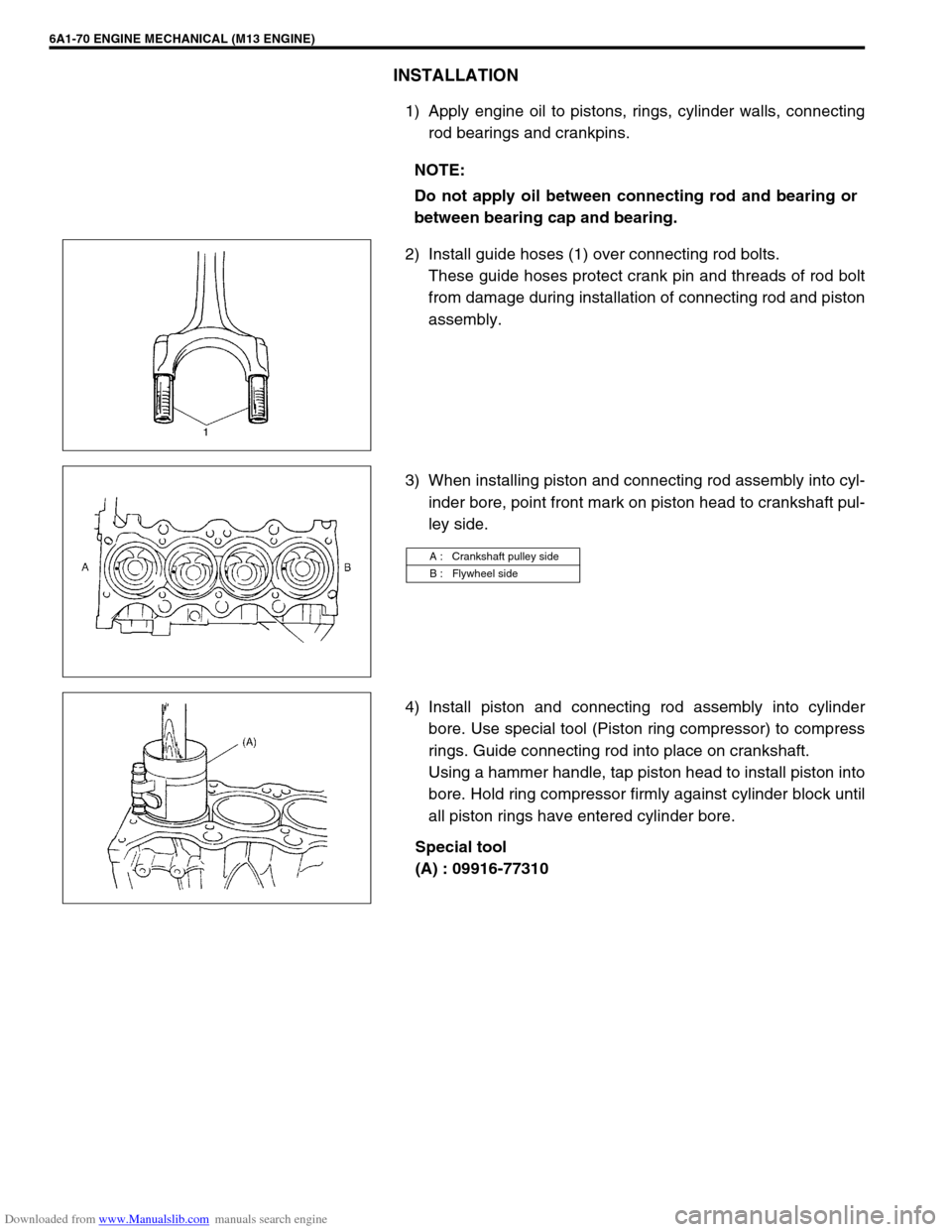
2) Install guide hoses (1) over connecting rod bolts.
These guide hoses protect crank pin and threads of rod bolt
from damage during installation of connecting rod and piston
assembly.
3) When installing piston and connecting rod assembly into cyl-
inder bore, point front mark on piston head to crankshaft pul-
ley side.
4) Install piston and connecting rod assembly into cylinder
bore. Use special tool (Piston ring compressor) to compress
rings. Guide connecting rod into place on crankshaft.
Using a hammer handle, tap piston head to install piston into
bore. Hold ring compressor firmly against cylinder block until
all piston rings have entered cylinder bore.
Special tool
(A) : 09916-77310 NOTE:
Do not apply oil between connecting rod and bearing or
between bearing cap and bearing.
A : Crankshaft pulley side
B : Flywheel side
Page 555 of 687
Downloaded from www.Manualslib.com manuals search engine 6A1-74 ENGINE MECHANICAL (M13 ENGINE)
a) For right hand steering vehicle:
With hose connected, detach A/C compressor from its
bracket.
b) For left hand steering vehicle:
i) Recover refrigerant from refrigeration system using recov-
ery and recycling equipment.
ii) Disconnect magnet clutch lead wire.
iii) Remove suction pipe and disconnect discharge pipe from
A/C compressor.
iv) Remove A/C compressor from its bracket.
When servicing above steps, refer to “Compressor” in Section 1B.
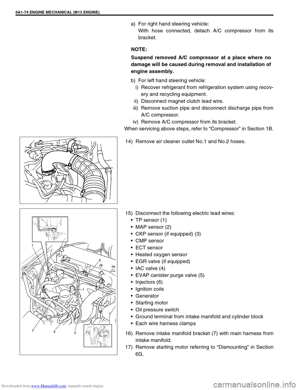
14) Remove air cleaner outlet No.1 and No.2 hoses.
15) Disconnect the following electric lead wires:
TP sensor (1)
MAP sensor (2)
CKP sensor (if equipped) (3)
CMP sensor
ECT sensor
Heated oxygen sensor
EGR valve (if equipped)
IAC valve (4)
EVAP canister purge valve (5)
Injectors (6)
Ignition coils
Generator
Starting motor
Oil pressure switch
Ground terminal from intake manifold and cylinder block
Each wire harness clamps
16) Remove intake manifold bracket (7) with main harness from
intake manifold.
17) Remove starting motor referring to “Dismounting” in Section
6G. NOTE:
Suspend removed A/C compressor at a place where no
damage will be caused during removal and installation of
engine assembly.
Page 556 of 687
Downloaded from www.Manualslib.com manuals search engine ENGINE MECHANICAL (M13 ENGINE) 6A1-75
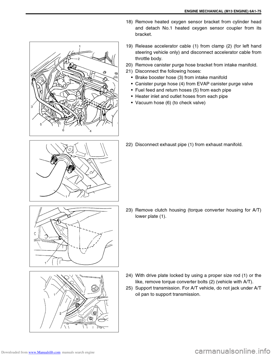
18) Remove heated oxygen sensor bracket from cylinder head
and detach No.1 heated oxygen sensor coupler from its
bracket.
19) Release accelerator cable (1) from clamp (2) (for left hand
steering vehicle only) and disconnect accelerator cable from
throttle body.
20) Remove canister purge hose bracket from intake manifold.
21) Disconnect the following hoses:
Brake booster hose (3) from intake manifold
Canister purge hose (4) from EVAP canister purge valve
Fuel feed and return hoses (5) from each pipe
Heater inlet and outlet hoses from each pipe
Vacuum hose (6) (to check valve)
22) Disconnect exhaust pipe (1) from exhaust manifold.
23) Remove clutch housing (torque converter housing for A/T)
lower plate (1).
24) With drive plate locked by using a proper size rod (1) or the
like, remove torque converter bolts (2) (vehicle with A/T).
25) Support transmission. For A/T vehicle, do not jack under A/T
oil pan to support transmission.
Page 557 of 687
Downloaded from www.Manualslib.com manuals search engine 6A1-76 ENGINE MECHANICAL (M13 ENGINE)
26) Remove bolts and nuts fastening cylinder block and trans-
mission.
27) Install board (1) or the like on A/C condenser. This prevents
damage to condenser fins when lifting and lowering engine
assembly.
28) Install lifting device.
29) Remove right and left engine mounting bracket bolts (1).
30) Before lifting engine, check to ensure all hoses, electric
wires and cables are disconnected from engine.
31) Remove engine assembly from chassis and transmission by
lifting a little, sliding toward front side, and then carefully
hoist engine assembly.
Page 558 of 687

Downloaded from www.Manualslib.com manuals search engine ENGINE MECHANICAL (M13 ENGINE) 6A1-77
INSTALLATION
1) Lower engine assembly into engine compartment.
Connect engine to transmission.
Hard-tighten bolts and nuts fastening cylinder block and
transmission.
2) Tighten right and left engine mounting bracket bolts to speci-
fied torque.
Tightening torque
Engine mounting bracket bolts
(a) : 50 N·m (5.0 kg-m, 36.5 lb-ft)
3) Tighten bolts and nuts fastening cylinder block and transmis-
sion to specified torque.
Tightening torque
Vehicle with M/T
Cylinder block and transmission fastening bolts and nuts
(a) : 94 N·m (9.4 kg-m, 68.0 lb-ft)
Vehicle with A/T
Cylinder block and transmission fastening bolts and nuts
(a) : 80 N·m (8.0 kg-m, 58.0 lb-ft)
4) Remove lifting device.
5) Reverse removal procedure for installation, noting the follow-
ing points.
Tighten torque converter bolts to specified torque (vehicle
with A/T).
Tightening torque
Torque converter bolts (a) : 20 N·m (2.0 kg-m, 14.5 lb-ft)
Page 560 of 687
Downloaded from www.Manualslib.com manuals search engine ENGINE MECHANICAL (M13 ENGINE) 6A1-79
Main Bearings, Crankshaft and Cylinder Block
Tightening torque 4. Venturi plug 12. Input shaft bearing
Do not reuse. 5. Main bearing 13. Flywheel
Apply engine oil to inside / sliding
surface.6. Sensor plate 14. Main bearing cap
“a” : 3 mm (0.12 in.) 7. Crankshaft timing sprocket key 15. Flywheel mounting bolt
: Apply sealant 99000-31110 to thread
part.
“b” : 2 mm (0.08 in.) 8. Crankshaft 16. Rear oil seal housing mounting bolt
1. CKP sensor (if equipped) 9. Thrust bearing 17. Main bearing cap No.2 bolt
2. Knock sensor 10. Rear oil seal housing
: Apply specified amount [A] of seal-
ant 99000-31150 to mating surface. 18. Main bearing cap No.1 bolt
1) Tighten all bolts to 50 N·m (5.0 kg-m)
2) Then, turn all bolts to 60°
3. Cylinder block 11. Rear oil seal