Page 530 of 687
Downloaded from www.Manualslib.com manuals search engine ENGINE MECHANICAL (M13 ENGINE) 6A1-49
REMOVAL
1) Relieve fuel pressure referring to “Fuel Pressure Relief Pro-
cedure” in Section 6.
2) Disconnect negative cable at battery.
3) Drain engine oil.
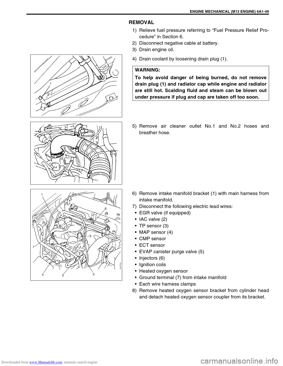
4) Drain coolant by loosening drain plug (1).
5) Remove air cleaner outlet No.1 and No.2 hoses and
breather hose.
6) Remove intake manifold bracket (1) with main harness from
intake manifold.
7) Disconnect the following electric lead wires:
EGR valve (if equipped)
IAC valve (2)
TP sensor (3)
MAP sensor (4)
CMP sensor
ECT sensor
EVAP canister purge valve (5)
Injectors (6)
Ignition coils
Heated oxygen sensor
Ground terminal (7) from intake manifold
Each wire harness clamps
8) Remove heated oxygen sensor bracket from cylinder head
and detach heated oxygen sensor coupler from its bracket. WARNING:
To help avoid danger of being burned, do not remove
drain plug (1) and radiator cap while engine and radiator
are still hot. Scalding fluid and steam can be blown out
under pressure if plug and cap are taken off too soon.
Page 538 of 687
Downloaded from www.Manualslib.com manuals search engine ENGINE MECHANICAL (M13 ENGINE) 6A1-57
Valve Springs
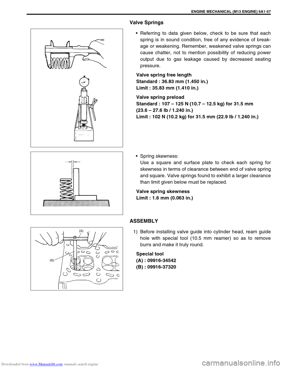
Referring to data given below, check to be sure that each
spring is in sound condition, free of any evidence of break-
age or weakening. Remember, weakened valve springs can
cause chatter, not to mention possibility of reducing power
output due to gas leakage caused by decreased seating
pressure.
Valve spring free length
Standard : 36.83 mm (1.450 in.)
Limit : 35.83 mm (1.410 in.)
Valve spring preload
Standard : 107 – 125 N (10.7 – 12.5 kg) for 31.5 mm
(23.6 – 27.6 lb / 1.240 in.)
Limit : 102 N (10.2 kg) for 31.5 mm (22.9 lb / 1.240 in.)
Spring skewness:
Use a square and surface plate to check each spring for
skewness in terms of clearance between end of valve spring
and square. Valve springs found to exhibit a larger clearance
than limit given below must be replaced.
Valve spring skewness
Limit : 1.6 mm (0.063 in.)
ASSEMBLY
1) Before installing valve guide into cylinder head, ream guide
hole with special tool (10.5 mm reamer) so as to remove
burrs and make it truly round.
Special tool
(A) : 09916-34542
(B) : 09916-37320
Page 543 of 687
Downloaded from www.Manualslib.com manuals search engine 6A1-62 ENGINE MECHANICAL (M13 ENGINE)
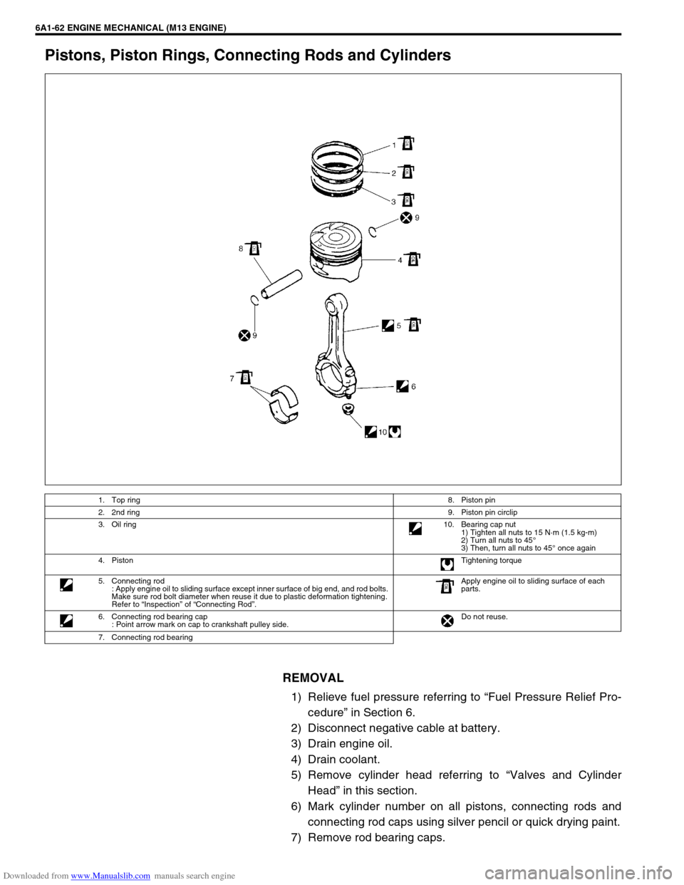
Pistons, Piston Rings, Connecting Rods and Cylinders
REMOVAL
1) Relieve fuel pressure referring to “Fuel Pressure Relief Pro-
cedure” in Section 6.
2) Disconnect negative cable at battery.
3) Drain engine oil.
4) Drain coolant.
5) Remove cylinder head referring to “Valves and Cylinder
Head” in this section.
6) Mark cylinder number on all pistons, connecting rods and
connecting rod caps using silver pencil or quick drying paint.
7) Remove rod bearing caps.
1. Top ring8. Piston pin
2. 2nd ring9. Piston pin circlip
3. Oil ring10. Bearing cap nut
1) Tighten all nuts to 15 N·m (1.5 kg-m)
2) Turn all nuts to 45°
3) Then, turn all nuts to 45° once again
4. PistonTightening torque
5. Connecting rod
: Apply engine oil to sliding surface except inner surface of big end, and rod bolts.
Make sure rod bolt diameter when reuse it due to plastic deformation tightening.
Refer to “Inspection” of “Connecting Rod”.Apply engine oil to sliding surface of each
parts.
6. Connecting rod bearing cap
: Point arrow mark on cap to crankshaft pulley side.Do not reuse.
7. Connecting rod bearing
Page 554 of 687
Downloaded from www.Manualslib.com manuals search engine ENGINE MECHANICAL (M13 ENGINE) 6A1-73
Unit Repair Overhaul
Engine Assembly
REMOVAL
1) Relieve fuel pressure referring to “Fuel Pressure Relief Pro-
cedure” in Section 6.
2) Disconnect negative cable at battery.
3) Remove engine hood after disconnecting windshield washer
hose.
4) Remove A/C compressor and/or P/S pump belt (if
equipped).
5) Remove generator belt.
6) Drain engine oil.
7) Drain coolant.
8) Disconnect radiator inlet and outlet hoses from each pipe.
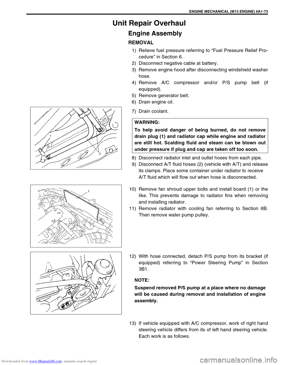
9) Disconnect A/T fluid hoses (2) (vehicle with A/T) and release
its clamps. Place some container under radiator to receive
A/T fluid which will flow out when hose is disconnected.
10) Remove fan shroud upper bolts and install board (1) or the
like. This prevents damage to radiator fins when removing
and installing radiator.
11) Remove radiator with cooling fan referring to Section 6B.
Then remove water pump pulley.
12) With hose connected, detach P/S pump from its bracket (if
equipped) referring to “Power Steering Pump” in Section
3B1.
13) If vehicle equipped with A/C compressor, work of right hand
steering vehicle differs from its of left hand steering vehicle.
Each work is as follows. WARNING:
To help avoid danger of being burned, do not remove
drain plug (1) and radiator cap while engine and radiator
are still hot. Scalding fluid and steam can be blown out
under pressure if plug and cap are taken off too soon.
NOTE:
Suspend removed P/S pump at a place where no damage
will be caused during removal and installation of engine
assembly.
Page 555 of 687
Downloaded from www.Manualslib.com manuals search engine 6A1-74 ENGINE MECHANICAL (M13 ENGINE)
a) For right hand steering vehicle:
With hose connected, detach A/C compressor from its
bracket.
b) For left hand steering vehicle:
i) Recover refrigerant from refrigeration system using recov-
ery and recycling equipment.
ii) Disconnect magnet clutch lead wire.
iii) Remove suction pipe and disconnect discharge pipe from
A/C compressor.
iv) Remove A/C compressor from its bracket.
When servicing above steps, refer to “Compressor” in Section 1B.
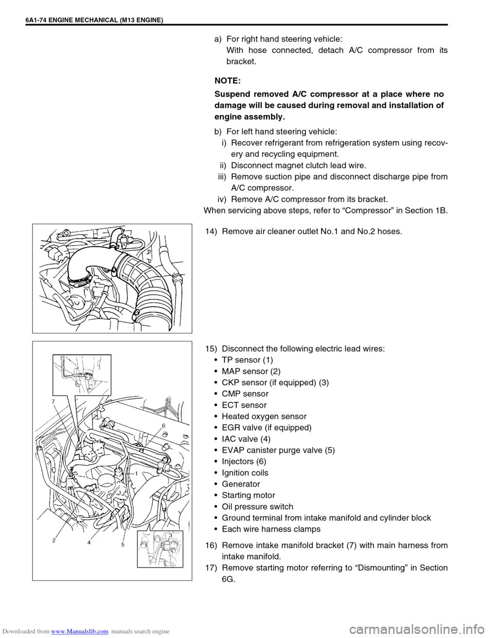
14) Remove air cleaner outlet No.1 and No.2 hoses.
15) Disconnect the following electric lead wires:
TP sensor (1)
MAP sensor (2)
CKP sensor (if equipped) (3)
CMP sensor
ECT sensor
Heated oxygen sensor
EGR valve (if equipped)
IAC valve (4)
EVAP canister purge valve (5)
Injectors (6)
Ignition coils
Generator
Starting motor
Oil pressure switch
Ground terminal from intake manifold and cylinder block
Each wire harness clamps
16) Remove intake manifold bracket (7) with main harness from
intake manifold.
17) Remove starting motor referring to “Dismounting” in Section
6G. NOTE:
Suspend removed A/C compressor at a place where no
damage will be caused during removal and installation of
engine assembly.
Page 574 of 687

Downloaded from www.Manualslib.com manuals search engine ENGINE MECHANICAL (M13 ENGINE) 6A1-93
Required Service Material
Tightening Torque Specification
MaterialRecommended SUZUKI product
(Part Number)Use
Sealant SUZUKI BOND NO. 1207C
(99000-31150)To apply to mating surface of cylinder block and oil
pan.
To apply to mating surface of cylinder block and
timing chain cover.
To apply to sealing surface of cylinder head cover.
To apply to mating surface to rear oil seal housing.
SUZUKI BOND NO. 1207B
(99000-31140)To apply to mating surface of cylinder block, cylin-
der head and timing chain cover.
SUZUKI BOND NO. 1215
(99000-31110)To flywheel (M/T) or drive plate (A/T) bolts.
Fastening partTightening torque
Nm kg-m lb-ft
Oil pressure switch 14.0 1.4 10.5
Camshaft housing bolts
(for replacement of shim)8.0 0.8 6.0
Camshaft housing bolts 11.0 1.1 8.0
Cylinder head cover bolts 8.0 0.8 6.0
Intake manifold bolts and nuts 25.0 2.5 18.0
Exhaust manifold bolts and nuts 55.0 5.5 40.0
Exhaust pipe bolts 50.0 5.0 36.5
Exhaust manifold stiffener bolts 50.0 5.0 36.5
Oil pump strainer bolt 11.0 1.1 8.0
Oil pump strainer bracket bolt 11.0 1.1 8.0
Oil pan bolts and nuts 11.0 1.1 8.0
Oil pan drain plug 50.0 5.0 36.5
Timing chain cover bolts and nut 23.0 2.3 17.0
Crankshaft pulley bolt 150.0 15.0 108.5
Oil pump rotor plate bolts 11.0 1.1 8.0
Timing chain No.1 guide bolts 9.0 0.9 6.5
Timing chain tensioner adjuster bolts 11.0 1.1 8.0
Venturi plug 5.0 0.5 3.5
Cylinder head bolt for M8 22.0 2.2 16.0
Cylinder head bolts for M10 a) Tighten 40 N·m
b) Turn 60°
c) Turn 60°a) Tighten 4.0 kg-m
b) Turn 60°
c) Turn 60°a) Tighten 29.0 lb-ft
b) Turn 60°
c) Turn 60°
Connecting rod bearing cap nuts a) Tighten 15 N·m
b) Turn 45°
c) Turn 45°a) Tighten 1.5 kg-m
b) Turn 45°
c) Turn 45°a) Tighten 11.0 lb-ft
b) Turn 45°
c) Turn 45°
Engine mounting bolts 50.0 5.0 36.5
Page 576 of 687
Downloaded from www.Manualslib.com manuals search engine ENGINE MECHANICAL (M13 ENGINE) 6A1-95
09915-67310 09915-77310 09915-78211 09916-14510
Vacuum gauge Oil pressure gauge Oil pressure gauge
attachmentValve lifter
09916-14521 09916-34542 09916-34550 09916-37320
Valve lifter attachment Reamer handle Reamer (5.5 mm) Reamer (10.5 mm)
09916-44910 09916-56011 09916-58210 09916-67020
Valve guide remover Valve guide installer
attachmentValve guide installer han-
dleTappet holder
09916-77310 09916-84511 09917-68221 09917-98221
Piston ring compressor Forceps Camshaft lock holder Valve stem seal installer
Page 580 of 687
Downloaded from www.Manualslib.com manuals search engine ENGINE COOLING 6B-3
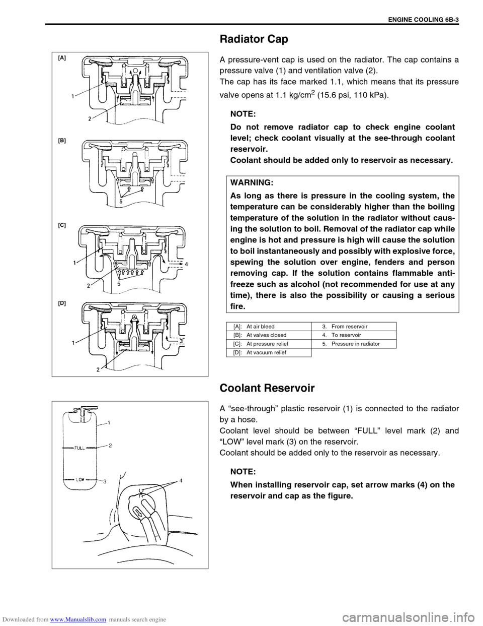
Radiator Cap
A pressure-vent cap is used on the radiator. The cap contains a
pressure valve (1) and ventilation valve (2).
The cap has its face marked 1.1, which means that its pressure
valve opens at 1.1 kg/cm
2 (15.6 psi, 110 kPa).
Coolant Reservoir
A “see-through” plastic reservoir (1) is connected to the radiator
by a hose.
Coolant level should be between “FULL” level mark (2) and
“LOW” level mark (3) on the reservoir.
Coolant should be added only to the reservoir as necessary.NOTE:
Do not remove radiator cap to check engine coolant
level; check coolant visually at the see-through coolant
reservoir.
Coolant should be added only to reservoir as necessary.
WARNING:
As long as there is pressure in the cooling system, the
temperature can be considerably higher than the boiling
temperature of the solution in the radiator without caus-
ing the solution to boil. Removal of the radiator cap while
engine is hot and pressure is high will cause the solution
to boil instantaneously and possibly with explosive force,
spewing the solution over engine, fenders and person
removing cap. If the solution contains flammable anti-
freeze such as alcohol (not recommended for use at any
time), there is also the possibility or causing a serious
fire.
[A]: At air bleed 3. From reservoir
[B]: At valves closed 4. To reservoir
[C]: At pressure relief 5. Pressure in radiator
[D]: At vacuum relief
NOTE:
When installing reservoir cap, set arrow marks (4) on the
reservoir and cap as the figure.