2005 SUZUKI JIMNY width
[x] Cancel search: widthPage 246 of 687
Downloaded from www.Manualslib.com manuals search engine WHEELS AND TIRES 3F-3
Replacement Wheels
Wheels must be replaced if they are bent, dented, have excessive
lateral or radial runout, leak air through welds, have elongated
bolt holes, if lug nuts won’t stay tight, or if they are heavily rusted.
Wheels with greater runout than shown in “How to Measure
Wheel Runout” may cause objectional vibrations.
Wheels for replacement must be equivalent to the originally
equipped wheels in load capacity, diameter, rim width, off-set and
mounting configuration. A wheel of improper size or type may
affect wheel and bearing life, brake cooling, speedometer / odom-
eter calibration, ground clearance to the body and chassis.
How To Measure Wheel Runout
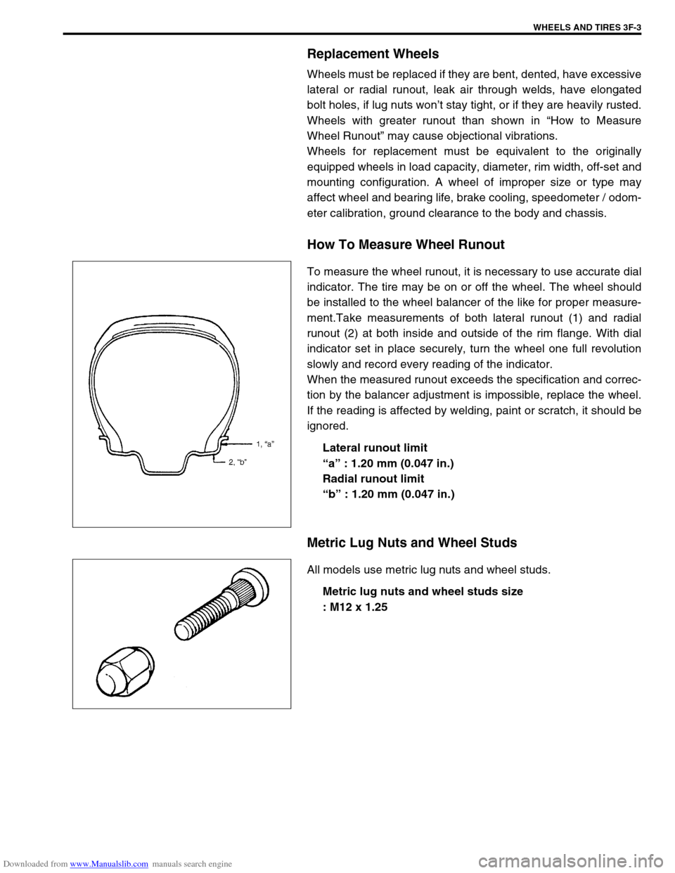
To measure the wheel runout, it is necessary to use accurate dial
indicator. The tire may be on or off the wheel. The wheel should
be installed to the wheel balancer of the like for proper measure-
ment.Take measurements of both lateral runout (1) and radial
runout (2) at both inside and outside of the rim flange. With dial
indicator set in place securely, turn the wheel one full revolution
slowly and record every reading of the indicator.
When the measured runout exceeds the specification and correc-
tion by the balancer adjustment is impossible, replace the wheel.
If the reading is affected by welding, paint or scratch, it should be
ignored.
Lateral runout limit
“a” : 1.20 mm (0.047 in.)
Radial runout limit
“b” : 1.20 mm (0.047 in.)
Metric Lug Nuts and Wheel Studs
All models use metric lug nuts and wheel studs.
Metric lug nuts and wheel studs size
: M12 x 1.25
Page 386 of 687

Downloaded from www.Manualslib.com manuals search engine ENGINE GENERAL INFORMATION AND DIAGNOSIS 6-29
∆✱
✱✱ ✱O2S B1 S2 (HEATED OXY-
GEN SENSOR-2)When engine is running at 2000 r/min. for
3 min or longer after warming up.0.01 – 0.95 V
∆✱
✱✱ ✱PSP SW No load to power steering. OFF
DESIRED IDLE
(DESIRED IDLE SPEED)At idling with no load after warming up, M/T
at neutral, A/T at “P” rangeM/T 700 r/min
A/T 750 r/min
TP SENSOR VOLT
(THROTTLE POSITION
SENSOR OUTPUT VOLT-
AGE)Ignition switch
ON / engine
stoppedThrottle valve fully closed More than 0.2 V
Throttle valve fully open Less than 4.8 V
INJ PULSE WIDTH (FUEL
INJECTION PULSE
WIDTH)At specified idle speed with no load after
warming up2.0 – 3.6 msec.
At 2500 r/min with no load after warming up 2.0 – 3.6 msec.
IAC FLOW DUTY (IDLE
AIR CONTROL FLOW
DUTY)At idling with no load after warming up 5 – 25 %
TOTAL FT B1 At specified idle speed after warming up– 35 – +35 %
BATTERY VOLTAGE Ignition switch ON / engine stop 12 – 15 V
CANIST PRG DUTY
(EVAP CANISTER PURGE
FLOW DUTY)–0 – 100 %
CLOSED THROT POS
(CLOSED THROTTLE
POSITION)Throttle valve at idle position ON
Throttle valve opens larger than idle posi-
tionOFF
FUEL CUTWhen engine is at fuel cut condition ON
Other than fuel cut condition OFF
A/C CONDENSER FANIgnition switch
ONA/C not operating OFF
A/C operating ON
ELECTRIC LOADIgnition switch ON / Headlight, small light,
heater fan and rear window defogger all
turned OFFOFF
Ignition switch ON / Headlight, small light,
heater fan or rear window defogger turned
ONON
A/C SWITCHEngine running after warming up, A/C not
operatingOFF
Engine running after warming up, A/C oper-
atingON
PNP SIGNAL (PARK / NEU-
TRAL POSITION SIGNAL)
A/T onlyIgnition switch
ONSelector lever in “P” or “N”
positionP/N Range
Selector lever in “R”, “D”,
“2” or “L” positionD Range
EGR VALVE At specified idle speed after warming up 0 %
∆FUEL TANK LEVEL–0 – 100 %
BAROMETRIC PRESS–Display the barometric pres-
sure
FUEL PUMPWithin 3 seconds after ignition switch ON or
engine runningON
Engine stop at ignition switch ON. OFF SCAN TOOL DATA CONDITION REFERENCE VALUES
Page 388 of 687

Downloaded from www.Manualslib.com manuals search engine ENGINE GENERAL INFORMATION AND DIAGNOSIS 6-31
THROTTLE POS (ABSOLUTE THROTTLE POSITION, %)
When throttle position sensor is fully closed position, throttle opening is indicated as 0% and 100% full open
position.
OXYGEN SENSOR B1 S1 (HEATED OXYGEN SENSOR-1, V)
It indicates output voltage of HO2S-1 installed on exhaust manifold (pre-catalyst).
OXYGEN SENSOR B1 S2 (HEATED OXYGEN SENSOR-2, V)
It indicates output voltage of HO2S-2 installed on exhaust pipe (post-catalyst). It is used to detect catalyst dete-
rioration.
DESIRED IDLE (DESIRED IDLE SPEED, rpm)
The Desired Idle Speed is an ECM internal parameter which indicates the ECM requested idle. If the engine is
not running, this number is not valid.
TP SENSOR VOLT (THROTTLE POSITION SENSOR OUTPUT VOLTAGE, V)
The Throttle Position Sensor reading provides throttle valve opening information in the form of voltage.
INJ PULSE WIDTH (FUEL INJECTION PULSE WIDTH, msec.)
This parameter indicates time of the injector drive (valve opening) pulse which is output from ECM (but injector
drive time of NO.1 cylinder for multiport fuel injection).
IAC FLOW DUTY (IDLE AIR (SPEED) CONTROL DUTY, %)
This parameter indicates current flow time rate within a certain set cycle of IAC valve (valve opening rate) which
controls the amount of bypass air (idle speed).
TOTAL FUEL TRIM (%)
The value of Total Fuel Trim is obtained by putting values of short Term Fuel Trim and Long Term Fuel Trim
together. This value indicates how much correction is necessary to keep the air / fuel mixture stoichiometrical.
BATTERY VOLTAGE (V)
This parameter indicates battery positive voltage inputted from main relay to ECM.
CANIST PURGE DUTY (EVAP CANISTER PURGE FLOW DUTY, %)
This parameter indicates valve ON (valve open) time rate within a certain set cycle of EVAP purge solenoid
valve which controls the amount of EVAP purge.
0% means that the purge valve is completely closed while 100% is a fully open valve.
CLOSED THROTTLE POSITION (ON / OFF)
This parameter will read ON when throttle valve is fully closed, or OFF when the throttle is not fully closed.
FUEL CUT (ON / OFF)
ON : Fuel being cut (output signal to injector is stopped)
OFF : Fuel not being cut
A/C CONDENSER FAN (A/C CONDENSER FAN RELAY, ON / OFF)
ON : Command for condenser fan relay operation being output.
OFF : Command for relay operation not being output.
ELECTRIC LOAD (ON / OFF)
ON : Headlight, small light, heater fan or rear window defogger ON signal inputted.
OFF : Above electric loads all turned OFF.
A/C SWITCH (ON / OFF)
ON : Command for A/C operation being output from ECM to A/C amplifier.
OFF : Command for A/C operation not being output.
Page 507 of 687
Downloaded from www.Manualslib.com manuals search engine 6A1-26 ENGINE MECHANICAL (M13 ENGINE)
INSTALLATION
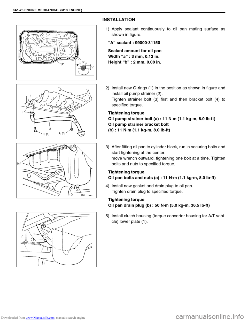
1) Apply sealant continuously to oil pan mating surface as
shown in figure.
“A” sealant : 99000-31150
Sealant amount for oil pan
Width “a” : 3 mm, 0.12 in.
Height “b” : 2 mm, 0.08 in.
2) Install new O-rings (1) in the position as shown in figure and
install oil pump strainer (2).
Tighten strainer bolt (3) first and then bracket bolt (4) to
specified torque.
Tightening torque
Oil pump strainer bolt (a) : 11 N·m (1.1 kg-m, 8.0 lb-ft)
Oil pump strainer bracket bolt
(b) : 11 N·m (1.1 kg-m, 8.0 lb-ft)
3) After fitting oil pan to cylinder block, run in securing bolts and
start tightening at the center:
move wrench outward, tightening one bolt at a time. Tighten
bolts and nuts to specified torque.
Tightening torque
Oil pan bolts and nuts (a) : 11 N·m (1.1 kg-m, 8.0 lb-ft)
4) Install new gasket and drain plug to oil pan.
Tighten drain plug to specified torque.
Tightening torque
Oil pan drain plug (b) : 50 N·m (5.0 kg-m, 36.5 lb-ft)
5) Install clutch housing (torque converter housing for A/T vehi-
cle) lower plate (1).
Page 512 of 687
Downloaded from www.Manualslib.com manuals search engine ENGINE MECHANICAL (M13 ENGINE) 6A1-31
INSPECTION
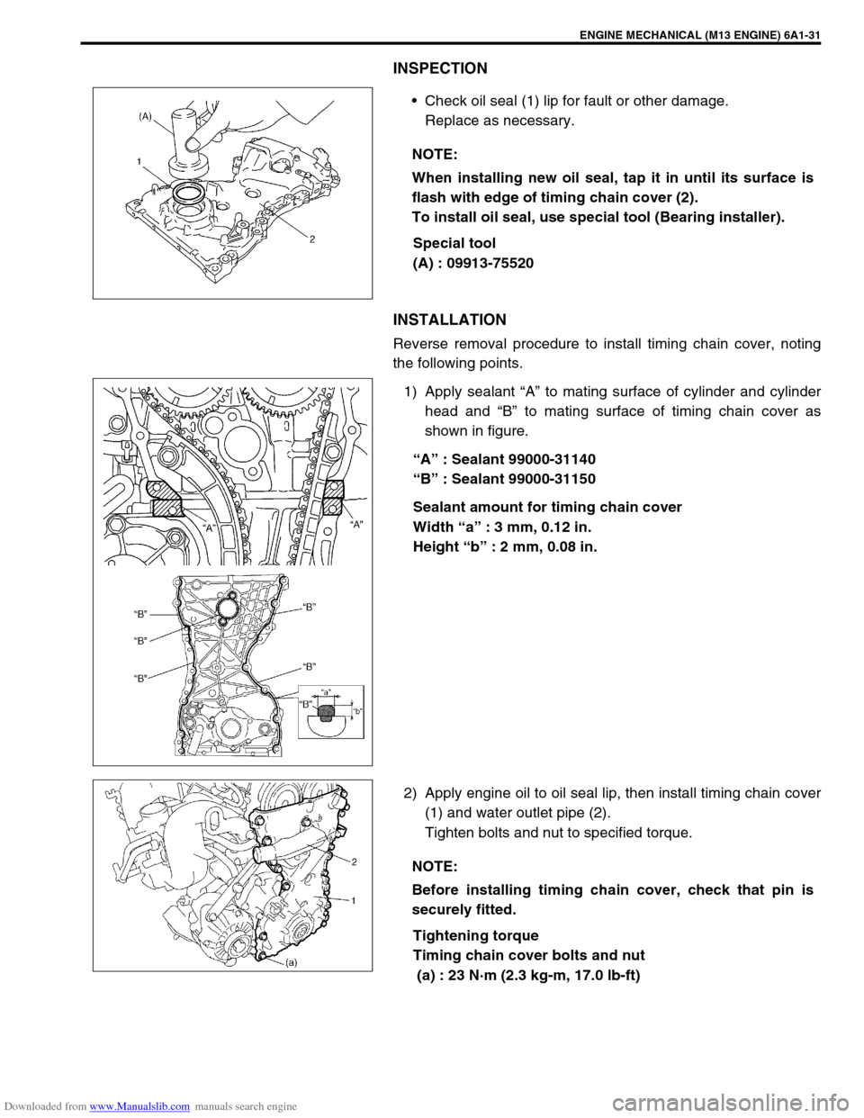
Check oil seal (1) lip for fault or other damage.
Replace as necessary.
Special tool
(A) : 09913-75520
INSTALLATION
Reverse removal procedure to install timing chain cover, noting
the following points.
1) Apply sealant “A” to mating surface of cylinder and cylinder
head and “B” to mating surface of timing chain cover as
shown in figure.
“A” : Sealant 99000-31140
“B” : Sealant 99000-31150
Sealant amount for timing chain cover
Width “a” : 3 mm, 0.12 in.
Height “b” : 2 mm, 0.08 in.
2) Apply engine oil to oil seal lip, then install timing chain cover
(1) and water outlet pipe (2).
Tighten bolts and nut to specified torque.
Tightening torque
Timing chain cover bolts and nut
(a) : 23 N·m (2.3 kg-m, 17.0 lb-ft) NOTE:
When installing new oil seal, tap it in until its surface is
flash with edge of timing chain cover (2).
To install oil seal, use special tool (Bearing installer).
NOTE:
Before installing timing chain cover, check that pin is
securely fitted.
Page 525 of 687

Downloaded from www.Manualslib.com manuals search engine 6A1-44 ENGINE MECHANICAL (M13 ENGINE)
Check clearance by using gauging plastic. Checking procedure is
as follows.
1) Clean housings and camshaft journals.
2) Remove all tappets with shims.
3) Install camshafts to cylinder head.
4) Place a piece of gauging plastic to full width of journal of
camshaft (parallel to camshaft).
5) Install camshaft housing.
6) Tighten camshaft housing bolts in such order as indicated in
figure a little at a time till they are tightened to specified
torque.
Tightening torque
Camshaft housing bolts (a) : 11 N·m (1.1 kg-m, 8.0 lb-ft)
7) Remove housing, and using scale (2) on gauging plastic (1)
envelop, measure gauging plastic width at its widest point.
Camshaft journal clearance
If measured camshaft journal clearance exceeds limit, measure
journal (housing) bore and outside diameter of camshaft journal.
Replace camshaft or cylinder head assembly whichever the dif-
ference from specification is greater.
Camshaft journal outside diameter [A]
Camshaft journal bore diameter [B] NOTE:
Do not rotate camshaft while gauging plastic is installed.
Standard Limit
0.045 – 0.087 mm
(0.0018 – 0.0034 in.)0.12 mm
(0.0047 in.)
Item Standard
No.126.934 – 26.955 mm
(1.0604 – 1.0612 in.)
Other22.934 – 22.955 mm
(0.9029 – 0.9037 in.)
Item Standard
No.127.000 – 27.021 mm
(1.0630 – 1.0638 in.)
Other23.000 – 23.021 mm
(0.9055 – 0.9063 in.)
Page 535 of 687
Downloaded from www.Manualslib.com manuals search engine 6A1-54 ENGINE MECHANICAL (M13 ENGINE)
Valves
Remove all carbon from valves.
Inspect each valve for wear, burn or distortion at its face and
stem end, as necessary, replace it.
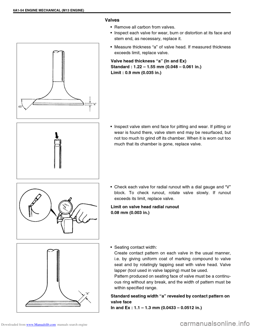
Measure thickness “a” of valve head. If measured thickness
exceeds limit, replace valve.
Valve head thickness “a” (In and Ex)
Standard : 1.22 – 1.55 mm (0.048 – 0.061 in.)
Limit : 0.9 mm (0.035 in.)
Inspect valve stem end face for pitting and wear. If pitting or
wear is found there, valve stem end may be resurfaced, but
not too much to grind off its chamber. When it is worn out too
much that its chamber is gone, replace valve.
Check each valve for radial runout with a dial gauge and “V”
block. To check runout, rotate valve slowly. If runout
exceeds its limit, replace valve.
Limit on valve head radial runout
0.08 mm (0.003 in.)
Seating contact width:
Create contact pattern on each valve in the usual manner,
i.e. by giving uniform coat of marking compound to valve
seat and by rotatingly tapping seat with valve head. Valve
lapper (tool used in valve lapping) must be used.
Pattern produced on seating face of valve must be a continu-
ous ring without any break, and the width of pattern must be
within specified range.
Standard seating width “a” revealed by contact pattern on
valve face
In and Ex : 1.1 – 1.3 mm (0.0433 – 0.0512 in.)
Page 536 of 687
Downloaded from www.Manualslib.com manuals search engine ENGINE MECHANICAL (M13 ENGINE) 6A1-55
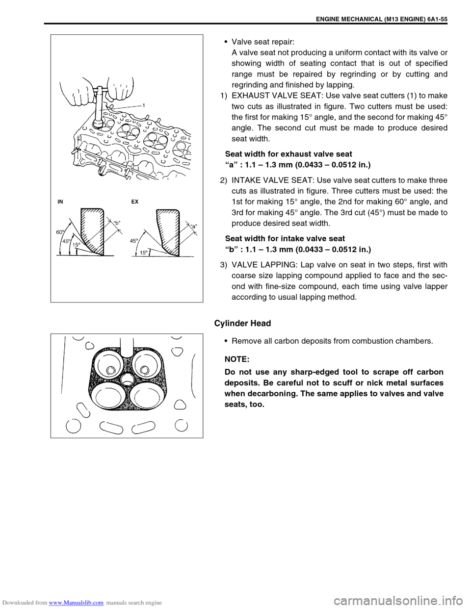
Valve seat repair:
A valve seat not producing a uniform contact with its valve or
showing width of seating contact that is out of specified
range must be repaired by regrinding or by cutting and
regrinding and finished by lapping.
1) EXHAUST VALVE SEAT: Use valve seat cutters (1) to make
two cuts as illustrated in figure. Two cutters must be used:
the first for making 15° angle, and the second for making 45°
angle. The second cut must be made to produce desired
seat width.
Seat width for exhaust valve seat
“a” : 1.1 – 1.3 mm (0.0433 – 0.0512 in.)
2) INTAKE VALVE SEAT: Use valve seat cutters to make three
cuts as illustrated in figure. Three cutters must be used: the
1st for making 15° angle, the 2nd for making 60° angle, and
3rd for making 45° angle. The 3rd cut (45°) must be made to
produce desired seat width.
Seat width for intake valve seat
“b” : 1.1 – 1.3 mm (0.0433 – 0.0512 in.)
3) VALVE LAPPING: Lap valve on seat in two steps, first with
coarse size lapping compound applied to face and the sec-
ond with fine-size compound, each time using valve lapper
according to usual lapping method.
Cylinder Head
Remove all carbon deposits from combustion chambers.
NOTE:
Do not use any sharp-edged tool to scrape off carbon
deposits. Be careful not to scuff or nick metal surfaces
when decarboning. The same applies to valves and valve
seats, too.