Page 549 of 687

Downloaded from www.Manualslib.com manuals search engine 6A1-68 ENGINE MECHANICAL (M13 ENGINE)
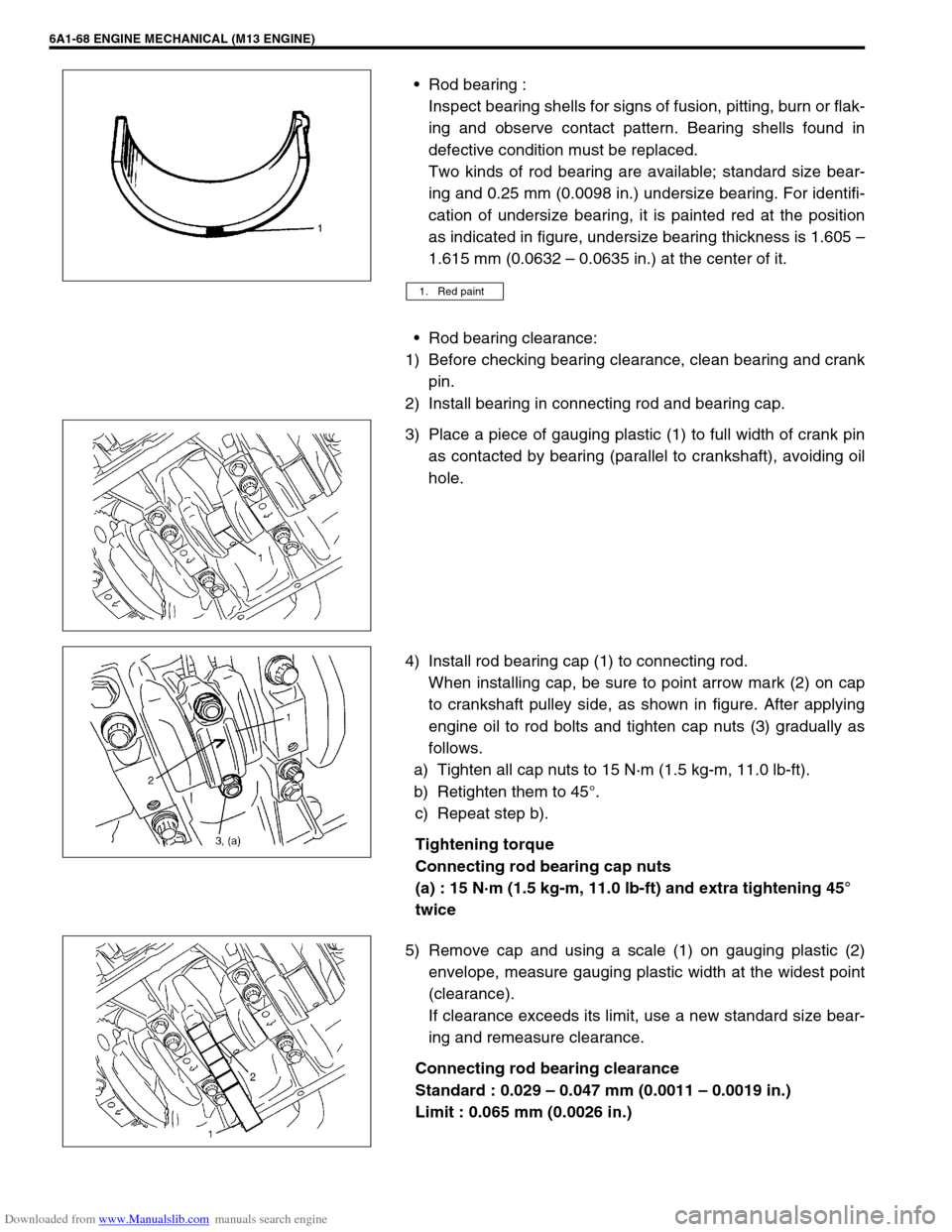
Rod bearing :
Inspect bearing shells for signs of fusion, pitting, burn or flak-
ing and observe contact pattern. Bearing shells found in
defective condition must be replaced.
Two kinds of rod bearing are available; standard size bear-
ing and 0.25 mm (0.0098 in.) undersize bearing. For identifi-
cation of undersize bearing, it is painted red at the position
as indicated in figure, undersize bearing thickness is 1.605 –
1.615 mm (0.0632 – 0.0635 in.) at the center of it.
Rod bearing clearance:
1) Before checking bearing clearance, clean bearing and crank
pin.
2) Install bearing in connecting rod and bearing cap.
3) Place a piece of gauging plastic (1) to full width of crank pin
as contacted by bearing (parallel to crankshaft), avoiding oil
hole.
4) Install rod bearing cap (1) to connecting rod.
When installing cap, be sure to point arrow mark (2) on cap
to crankshaft pulley side, as shown in figure. After applying
engine oil to rod bolts and tighten cap nuts (3) gradually as
follows.
a) Tighten all cap nuts to 15 N·m (1.5 kg-m, 11.0 lb-ft).
b) Retighten them to 45°.
c) Repeat step b).
Tightening torque
Connecting rod bearing cap nuts
(a) : 15 N·m (1.5 kg-m, 11.0 lb-ft) and extra tightening 45°
twice
5) Remove cap and using a scale (1) on gauging plastic (2)
envelope, measure gauging plastic width at the widest point
(clearance).
If clearance exceeds its limit, use a new standard size bear-
ing and remeasure clearance.
Connecting rod bearing clearance
Standard : 0.029 – 0.047 mm (0.0011 – 0.0019 in.)
Limit : 0.065 mm (0.0026 in.)
1. Red paint
Page 564 of 687

Downloaded from www.Manualslib.com manuals search engine ENGINE MECHANICAL (M13 ENGINE) 6A1-83
Upper half of bearing (1) has an oil groove (2) as shown in
figure.
Install this half with oil groove to cylinder block.
Lower half of bearing does not have an oil groove.
Visual inspection
Check bearings for pitting, scratches, wear or damage.
If any malcondition is found, replace both upper and lower halves.
Do not replace either half without replacing the other half.
Main bearing clearance
Check clearance by using gauging plastic according to the follow-
ing procedure.
1) Remove bearing caps.
2) Clean bearings and main journals.
3) Place a piece of gauging plastic (1) the full width of bearing
(parallel to crankshaft) on journal, avoiding oil hole.
4) Tighten bearing cap No.1 bolts (1) – (10) and No.2 bolts (11)
– (20) gradually as follows.
a) Tighten bolts (1) – (10) to 30 N·m (3.0 kg-m, 22.0 lb-ft)
according to numerical order in figure.
b) In the same manner as in Step a), tighten them to 50 N·m
(5.0 kg-m, 36.5 lb-ft).
c) In the same manner as in step a), retighten them to 60°.
d) Tighten bolts (11) – (20) to 22 N·m (2.2 kg-m, 16.0 lb-ft)
according to numerical order in figure.
Tightening torque
Crankshaft bearing No.1 bolts (1) – (10) :
50 N·m (5.0 kg-m, 36.5 lb-ft) and extra tightening 60°
Crankshaft bearing No.2 bolts (11) – (20) :
22 N·m (2.2 kg-m, 16.0 lb-ft)
NOTE:
Do not rotate crankshaft while gauging plastic is
installed.
Page 565 of 687

Downloaded from www.Manualslib.com manuals search engine 6A1-84 ENGINE MECHANICAL (M13 ENGINE)
5) Remove bearing caps and using scale (1) on gauging plastic
(2) envelop, measure gauging plastic width at its widest
point. If clearance exceeds its limit, replace bearing. Always
replace both upper and lower inserts as a unit.
A new standard bearing may produce proper clearance. If
not, it will be necessary to regrind crankshaft journal for use
of 0.25 mm undersize bearing.
After selecting new bearing, recheck clearance.
Main bearing clearance
Standard : 0.025 – 0.045 mm (0.0010 – 0.0018 in.)
Limit : 0.065 mm (0.0026 in.)
Selection of main bearings
STANDARD BEARING:
If bearing is in malcondition, or bearing clearance is out of specifi-
cation, select a new standard bearing according to the following
procedure and install it.
1) First check journal diameter. As shown in figure, crank web
No.2 has stamped numbers.
Three kinds of numbers (“1”, “2” and “3”) represent the fol-
lowing journal diameters.
Stamped numbers on crank web No.2 represent journal
diameters marked with an arrow in figure respectively.
For example, stamped number “1” indicates that correspond-
ing journal diameter is 44.994 – 45.000 mm (1.7714 –
1.7717 in.).
Crankshaft journal diameter NOTE:
After checking the bearing clearance, check for thread
deformation of each bearing cap No.1 bolt according to
previous mentioned Step 4) once again.
Stamped numbers Journal diameter
144.994 – 45.000 mm
(1.7714 – 1.7717 in.)
244.988 – 44.994 mm
(1.7712 – 1.7714 in.)
344.982 – 44.988 mm
(1.7709 – 1.7712 in.)
Page 572 of 687

Downloaded from www.Manualslib.com manuals search engine ENGINE MECHANICAL (M13 ENGINE) 6A1-91
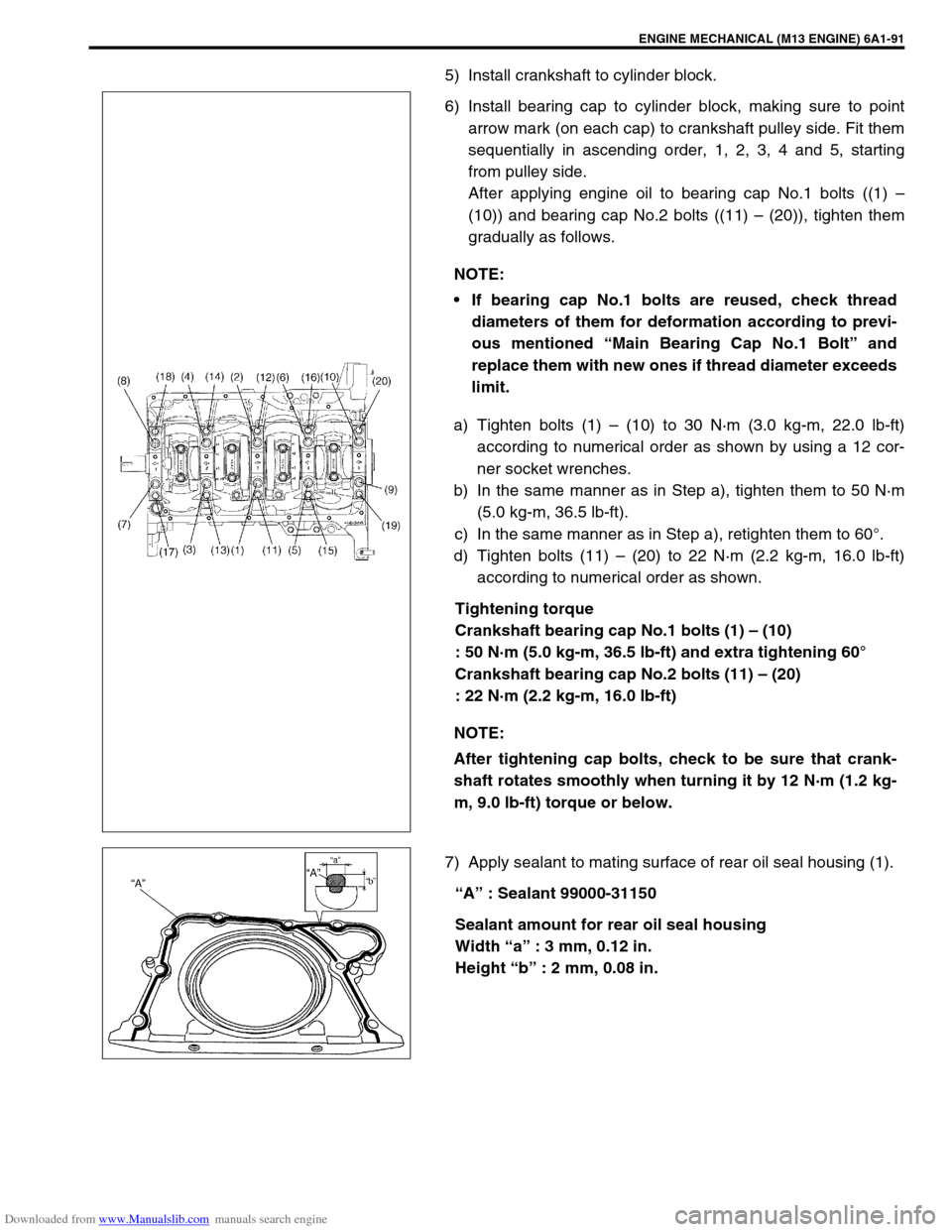
5) Install crankshaft to cylinder block.
6) Install bearing cap to cylinder block, making sure to point
arrow mark (on each cap) to crankshaft pulley side. Fit them
sequentially in ascending order, 1, 2, 3, 4 and 5, starting
from pulley side.
After applying engine oil to bearing cap No.1 bolts ((1) –
(10)) and bearing cap No.2 bolts ((11) – (20)), tighten them
gradually as follows.
a) Tighten bolts (1) – (10) to 30 N·m (3.0 kg-m, 22.0 lb-ft)
according to numerical order as shown by using a 12 cor-
ner socket wrenches.
b) In the same manner as in Step a), tighten them to 50 N·m
(5.0 kg-m, 36.5 lb-ft).
c) In the same manner as in Step a), retighten them to 60°.
d) Tighten bolts (11) – (20) to 22 N·m (2.2 kg-m, 16.0 lb-ft)
according to numerical order as shown.
Tightening torque
Crankshaft bearing cap No.1 bolts (1) – (10)
: 50 N·m (5.0 kg-m, 36.5 lb-ft) and extra tightening 60°
Crankshaft bearing cap No.2 bolts (11) – (20)
: 22 N·m (2.2 kg-m, 16.0 lb-ft)
7) Apply sealant to mating surface of rear oil seal housing (1).
“A” : Sealant 99000-31150
Sealant amount for rear oil seal housing
Width “a” : 3 mm, 0.12 in.
Height “b” : 2 mm, 0.08 in. NOTE:
If bearing cap No.1 bolts are reused, check thread
diameters of them for deformation according to previ-
ous mentioned “Main Bearing Cap No.1 Bolt” and
replace them with new ones if thread diameter exceeds
limit.
NOTE:
After tightening cap bolts, check to be sure that crank-
shaft rotates smoothly when turning it by 12 N·m (1.2 kg-
m, 9.0 lb-ft) torque or below.
Page 593 of 687

Downloaded from www.Manualslib.com manuals search engine 6B-16 ENGINE COOLING
INSPECTION
Rotate water pump by hand to check for smooth operation.
If pump does not rotate smoothly or makes an abnormal
noise, replace it.
INSTALLATION
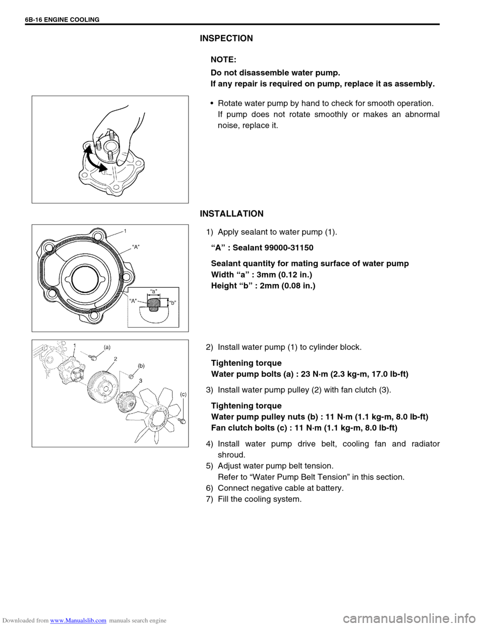
1) Apply sealant to water pump (1).
“A” : Sealant 99000-31150
Sealant quantity for mating surface of water pump
Width “a” : 3mm (0.12 in.)
Height “b” : 2mm (0.08 in.)
2) Install water pump (1) to cylinder block.
Tightening torque
Water pump bolts (a) : 23 N·m (2.3 kg-m, 17.0 lb-ft)
3) Install water pump pulley (2) with fan clutch (3).
Tightening torque
Water pump pulley nuts (b) : 11 N·m (1.1 kg-m, 8.0 lb-ft)
Fan clutch bolts (c) : 11 N·m (1.1 kg-m, 8.0 lb-ft)
4) Install water pump drive belt, cooling fan and radiator
shroud.
5) Adjust water pump belt tension.
Refer to “Water Pump Belt Tension” in this section.
6) Connect negative cable at battery.
7) Fill the cooling system.NOTE:
Do not disassemble water pump.
If any repair is required on pump, replace it as assembly.