2005 SUZUKI JIMNY rear diff
[x] Cancel search: rear diffPage 4 of 687
Downloaded from www.Manualslib.com manuals search engine TABLE OF CONTENTS
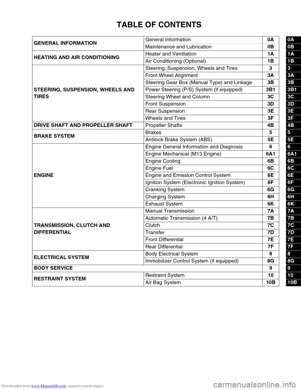
GENERAL INFORMATIONGeneral Information0A0A
Maintenance and Lubrication0B
0B
HEATING AND AIR CONDITIONINGHeater and Ventilation1A
1A
Air Conditioning (Optional)1B
1B
STEERING, SUSPENSION, WHEELS AND
TIRESSteering, Suspension, Wheels and Tires3
3
Front Wheel Alignment3A
3A
Steering Gear Box (Manual Type) and Linkage3B
3B
Power Steering (P/S) System (if equipped)3B1
3B1
Steering Wheel and Column3C
3C
Front Suspension3D
3D
Rear Suspension3E
3E
Wheels and Tires3F
3F
DRIVE SHAFT AND PROPELLER SHAFT
Propeller Shafts4B
4B
BRAKE SYSTEMBrakes5
5
Antilock Brake System (ABS)5E
5E
ENGINEEngine General Information and Diagnosis6
6
Engine Mechanical (M13 Engine)6A1
6A1
Engine Cooling6B
6B
Engine Fuel6C
6C
Engine and Emission Control System6E
6E
Ignition System (Electronic Ignition System)6F
6F
Cranking System6G
6G
Charging System6H
6H
Exhaust System6K
6K
TRANSMISSION, CLUTCH AND
DIFFERENTIALManual Transmission7A
7A
Automatic Transmission (4 A/T)7B
7B
Clutch7C
7C
Transfer7D
7D
Front Differential7E
7E
Rear Differential7F
7F
ELECTRICAL SYSTEMBody Electrical System8
8
Immobilizer Control System (if equipped)8G
8G
BODY SERVICE9
9
RESTRAINT SYSTEMRestraint System10
10
Air Bag System10B
10B
Page 43 of 687
Downloaded from www.Manualslib.com manuals search engine 0B-12 MAINTENANCE AND LUBRICATION
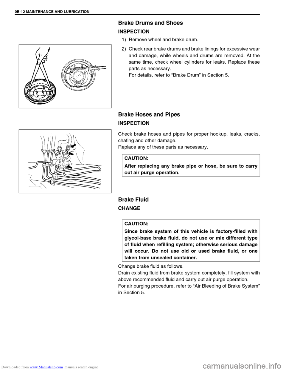
Brake Drums and Shoes
INSPECTION
1) Remove wheel and brake drum.
2) Check rear brake drums and brake linings for excessive wear
and damage, while wheels and drums are removed. At the
same time, check wheel cylinders for leaks. Replace these
parts as necessary.
For details, refer to “Brake Drum” in Section 5.
Brake Hoses and Pipes
INSPECTION
Check brake hoses and pipes for proper hookup, leaks, cracks,
chafing and other damage.
Replace any of these parts as necessary.
Brake Fluid
CHANGE
Change brake fluid as follows.
Drain existing fluid from brake system completely, fill system with
above recommended fluid and carry out air purge operation.
For air purging procedure, refer to “Air Bleeding of Brake System”
in Section 5.
CAUTION:
After replacing any brake pipe or hose, be sure to carry
out air purge operation.
CAUTION:
Since brake system of this vehicle is factory-filled with
glycol-base brake fluid, do not use or mix different type
of fluid when refilling system; otherwise serious damage
will occur. Do not use old or used brake fluid, or one
taken from unsealed container.
Page 48 of 687
Downloaded from www.Manualslib.com manuals search engine MAINTENANCE AND LUBRICATION 0B-17
FLUID COOLER HOSE CHANGE
Replace inlet and outlet hoses of cooler hose and their clamps.
For replacement procedure, refer to “Oil Cooler Hoses” in Section
7B.
Transfer and Differential Oil
INSPECTION
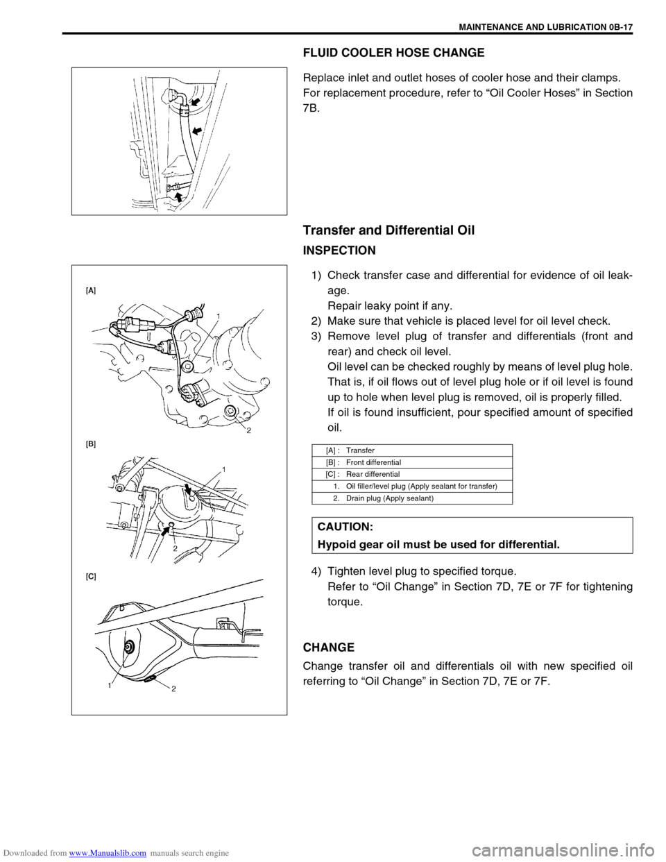
1) Check transfer case and differential for evidence of oil leak-
age.
Repair leaky point if any.
2) Make sure that vehicle is placed level for oil level check.
3) Remove level plug of transfer and differentials (front and
rear) and check oil level.
Oil level can be checked roughly by means of level plug hole.
That is, if oil flows out of level plug hole or if oil level is found
up to hole when level plug is removed, oil is properly filled.
If oil is found insufficient, pour specified amount of specified
oil.
4) Tighten level plug to specified torque.
Refer to “Oil Change” in Section 7D, 7E or 7F for tightening
torque.
CHANGE
Change transfer oil and differentials oil with new specified oil
referring to “Oil Change” in Section 7D, 7E or 7F.
[A] : Transfer
[B] : Front differential
[C] : Rear differential
1. Oil filler/level plug (Apply sealant for transfer)
2. Drain plug (Apply sealant)
CAUTION:
Hypoid gear oil must be used for differential.
Page 53 of 687

Downloaded from www.Manualslib.com manuals search engine 0B-22 MAINTENANCE AND LUBRICATION
Recommended Fluids and Lubricants
Engine oilSE, SF, SG, SH, SJ or SL
(Refer to “Engine Oil and Oil Filter” in this section for engine oil viscos-
ity.)
Engine coolant
(Ethylene glycol base coolant)“Antifreeze/Anticorrosion coolant”
Brake fluid DOT 3
Manual transmission oil Refer to “Maintenance Service” in Section 7A.
Transfer oil Refer to “Oil Change” in Section 7D.
Differential oil (front & rear) Refer to “Oil Change” in Section 7E and 7F.
Automatic transmission fluid
An equivalent of DEXRON
®-IIE or DEXRON®-III
Power steering fluid
An equivalent of DEXRON
®-II, DEXRON®-IIE or DEXRON®-III
Clutch linkage pivot points
Water resistance chassis grease
(SUZUKI SUPER GREASE A 99000-25010)
Steering knuckle seal
Door hinges
Engine oil or water resistance chassis grease
Hood latch assembly
Key lock cylinder Spray lubricant
Page 114 of 687

Downloaded from www.Manualslib.com manuals search engine STEERING, SUSPENSION, WHEELS AND TIRES 3-5
Tire Diagnosis
Irregular and/or Premature Wear
Irregular and premature wear has many possible causes. Some
of them are: incorrect inflation pressures lack of tire rotation, driv-
ing habits, improper alignment.
If the following conditions are noted rotation is in order:
Front tire wear is different from rear.
Uneven wear exists across the tread of any tire.
Left front and right front tire wear is unequal.
Left rear and right rear tire wear is unequal.
There is cupping, flat spotting, etc.
A wheel alignment check is in order if the following conditions are
noted:
Left front and right front tire wear is unequal.
Wear is uneven across the tread of any front tire.
Front tire treads have scuffed appearance with “feather”
edges on one side of tread ribs or blocks.
Wear Indicators
The original equipment tires have built-in tread wear indicators to
show when tires need replacement. These indicators will appear
as 12 mm (0.47 inch) wide bands when the tire tread depth
becomes 1.6 mm (0.063 inch). When the indicators appear in 3 or
more grooves at 6 locations, tire replacement is recommended.
Radial Tire Waddle
Waddle is side to side movement at the front and/or rear of the
vehicle. It is caused by the steel belt not being straight within the
tire. It is most noticeable at low speed, 5 to 30 mph. It is possible
to road test a vehicle and tell on which end of the vehicle the
faulty tire is located. If the waddle tire is on the rear, the rear end
of the vehicle will shake from side to side or “waddle”. From the
driver’s seat it feels as though someone is pushing on the side of
the vehicle. If the faulty tire is on the front, the waddle is more
visual. The front sheet metal appears to be moving back and forth
and the driver feels as though he is at the pivot point in the vehi-
cle. Waddle can be quickly diagnosed by using a Tire Problem
Detector (TPD) and following the equipment manufacturer’s rec-
ommendations.
If a TPD is not available, the more time consuming method of sub-
stituting known good tire / wheel assemblies on the problem vehi-
cle can be used as follows:
[A] : Hard cornering, under inflation or lack of tire rotation
[B] : Incorrect wheel alignment, tire construction not uniform or wheel heavy acceleration
Page 116 of 687

Downloaded from www.Manualslib.com manuals search engine STEERING, SUSPENSION, WHEELS AND TIRES 3-7
Radial Tire Lead
“Lead” is the deviation of the vehicle from a straight path on a level rod even with no pressure on the steering
wheel.
Lead is usually caused by:
1) Incorrect alignment.
2) Uneven brake adjustment.
3) Tire construction.
The way in which a tire is built can produce lead in a vehicle. An example of this is placement of the belt. Off
center belts on radial tires can cause the tire to develop a side force while rolling straight down the road. If one
side of the tire has a little larger diameter than the other, the tire will tend to roll to one side. This will develop a
side force which can produce vehicle lead.
The procedure in above figure (Lead Diagnosis) should be used to make sure that front alignment is not mis-
taken for tire lead.
1) Part of the lead diagnosis procedure is different from the proper tire rotation pattern currently in the owner
and service manuals. If a medium to high mileage tire is moved to the other side of the vehicle, be sure to
check that ride roughness has not developed.
2) Rear tires will not cause lead.
Vibration Diagnosis
Wheel unbalance causes most of the highway speed vibration problems. If a vibration remains after dynamic
balancing, its possible causes are as follows.
1) Tire runout.
2) Wheel runout.
3) Tire stiffness variation.
Measuring tire and/or wheel free runout will uncover only part of the problem. All three causes, known as loaded
radial runout, must be checked by using a Tire Problem Detector (TPD). If TPD is not available, alternative
method of substituting known good tire and wheel assemblies on the problem vehicle can be used, although it
takes a longer time.
[A] : Tire out of round 1. Smooth road
[B] : Tire stiffness variation 2. Suspension movement (loaded runout)
[C] : Rim bent or out of round
Page 227 of 687
Downloaded from www.Manualslib.com manuals search engine 3E-8 REAR SUSPENSION
INSTALLATION
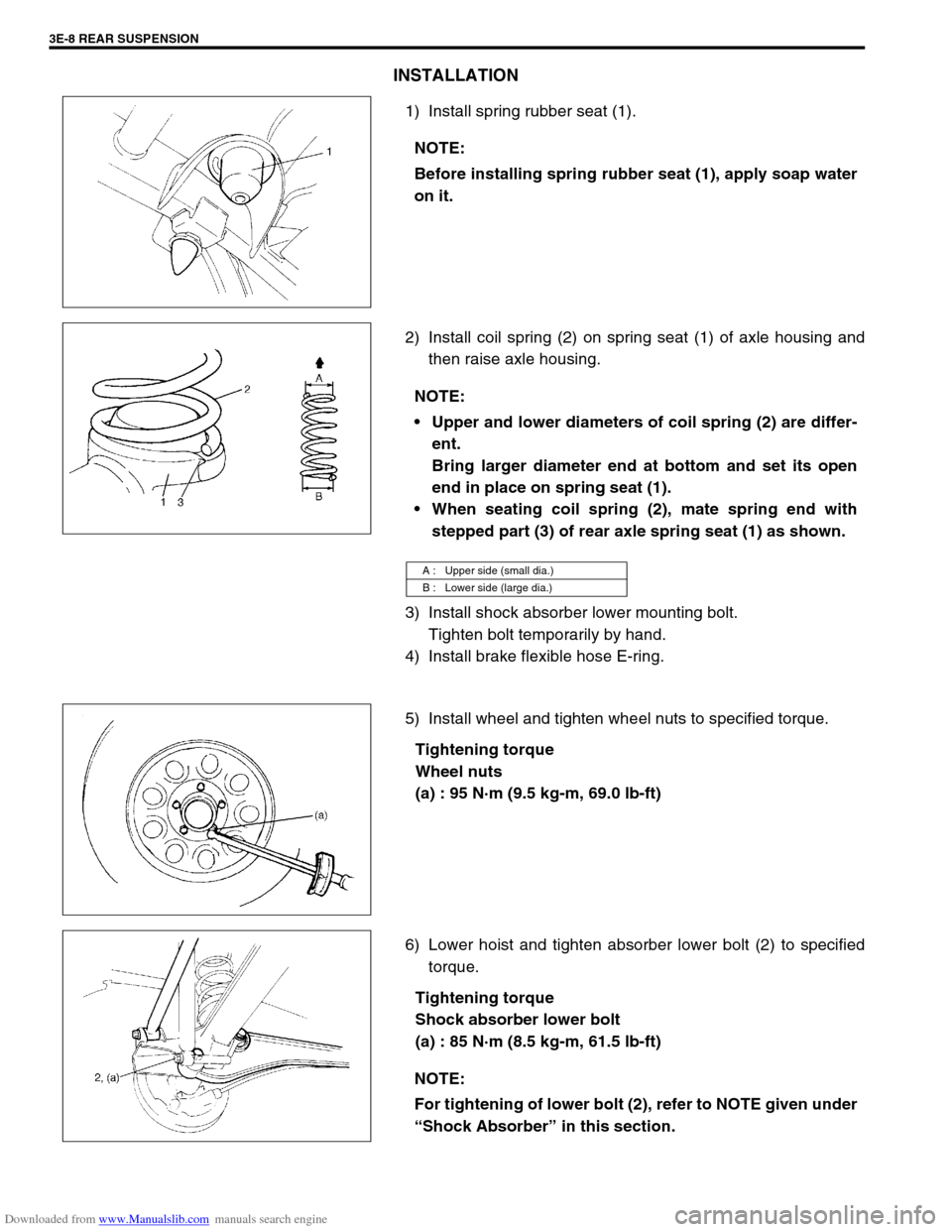
1) Install spring rubber seat (1).
2) Install coil spring (2) on spring seat (1) of axle housing and
then raise axle housing.
3) Install shock absorber lower mounting bolt.
Tighten bolt temporarily by hand.
4) Install brake flexible hose E-ring.
5) Install wheel and tighten wheel nuts to specified torque.
Tightening torque
Wheel nuts
(a) : 95 N·m (9.5 kg-m, 69.0 lb-ft)
6) Lower hoist and tighten absorber lower bolt (2) to specified
torque.
Tightening torque
Shock absorber lower bolt
(a) : 85 N·m (8.5 kg-m, 61.5 lb-ft) NOTE:
Before installing spring rubber seat (1), apply soap water
on it.
NOTE:
Upper and lower diameters of coil spring (2) are differ-
ent.
Bring larger diameter end at bottom and set its open
end in place on spring seat (1).
When seating coil spring (2), mate spring end with
stepped part (3) of rear axle spring seat (1) as shown.
A : Upper side (small dia.)
B : Lower side (large dia.)
NOTE:
For tightening of lower bolt (2), refer to NOTE given under
“Shock Absorber” in this section.
Page 235 of 687
Downloaded from www.Manualslib.com manuals search engine 3E-16 REAR SUSPENSION
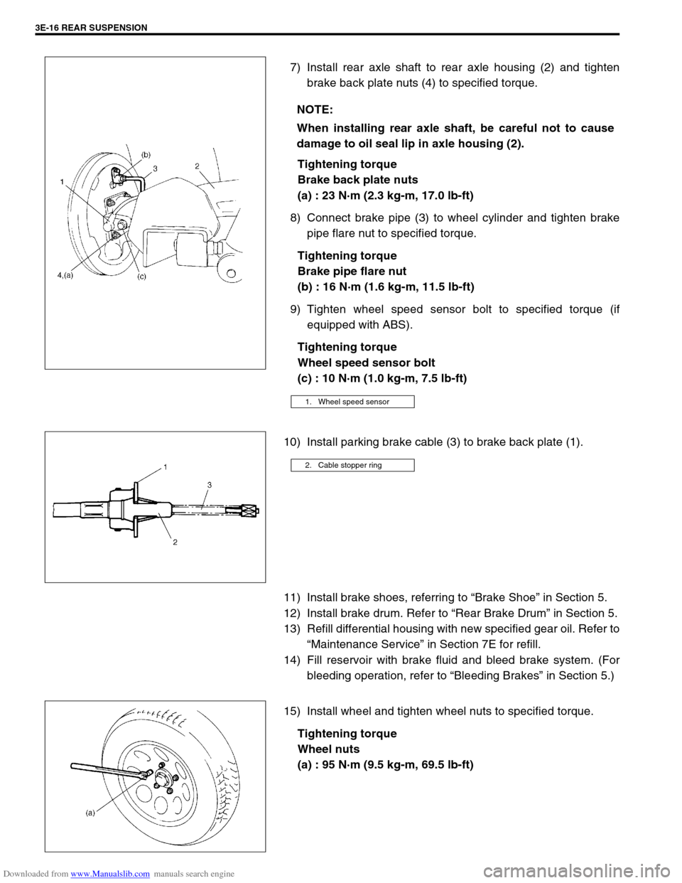
7) Install rear axle shaft to rear axle housing (2) and tighten
brake back plate nuts (4) to specified torque.
Tightening torque
Brake back plate nuts
(a) : 23 N·m (2.3 kg-m, 17.0 lb-ft)
8) Connect brake pipe (3) to wheel cylinder and tighten brake
pipe flare nut to specified torque.
Tightening torque
Brake pipe flare nut
(b) : 16 N·m (1.6 kg-m, 11.5 lb-ft)
9) Tighten wheel speed sensor bolt to specified torque (if
equipped with ABS).
Tightening torque
Wheel speed sensor bolt
(c) : 10 N·m (1.0 kg-m, 7.5 lb-ft)
10) Install parking brake cable (3) to brake back plate (1).
11) Install brake shoes, referring to “Brake Shoe” in Section 5.
12) Install brake drum. Refer to “Rear Brake Drum” in Section 5.
13) Refill differential housing with new specified gear oil. Refer to
“Maintenance Service” in Section 7E for refill.
14) Fill reservoir with brake fluid and bleed brake system. (For
bleeding operation, refer to “Bleeding Brakes” in Section 5.)
15) Install wheel and tighten wheel nuts to specified torque.
Tightening torque
Wheel nuts
(a) : 95 N·m (9.5 kg-m, 69.5 lb-ft) NOTE:
When installing rear axle shaft, be careful not to cause
damage to oil seal lip in axle housing (2).
1. Wheel speed sensor
2. Cable stopper ring