Page 236 of 687
Downloaded from www.Manualslib.com manuals search engine REAR SUSPENSION 3E-17
16) Upon completion of all jobs, depress brake pedal with about
30 kg (66 lbs) load over ten times so as to obtain proper
drum-to shoe clearance.
Adjust parking brake cable. (For adjustment, refer to “Parking
Brake Check and Adjustment” in Section 5.)
17) Tighten parking brake lever cover screws.
18) Check to ensure that brake drum is free from dragging and
proper braking is obtained. Then remove vehicle from hoist
and perform brake test (foot brake and parking brake).
19) Check each installed part for oil leakage.
Rear Axle Shaft Inner Oil Seal
REMOVAL
1) Remove rear axle shaft. For details, refer to “Rear Axle Shaft
and Wheel Bearing” in this section.
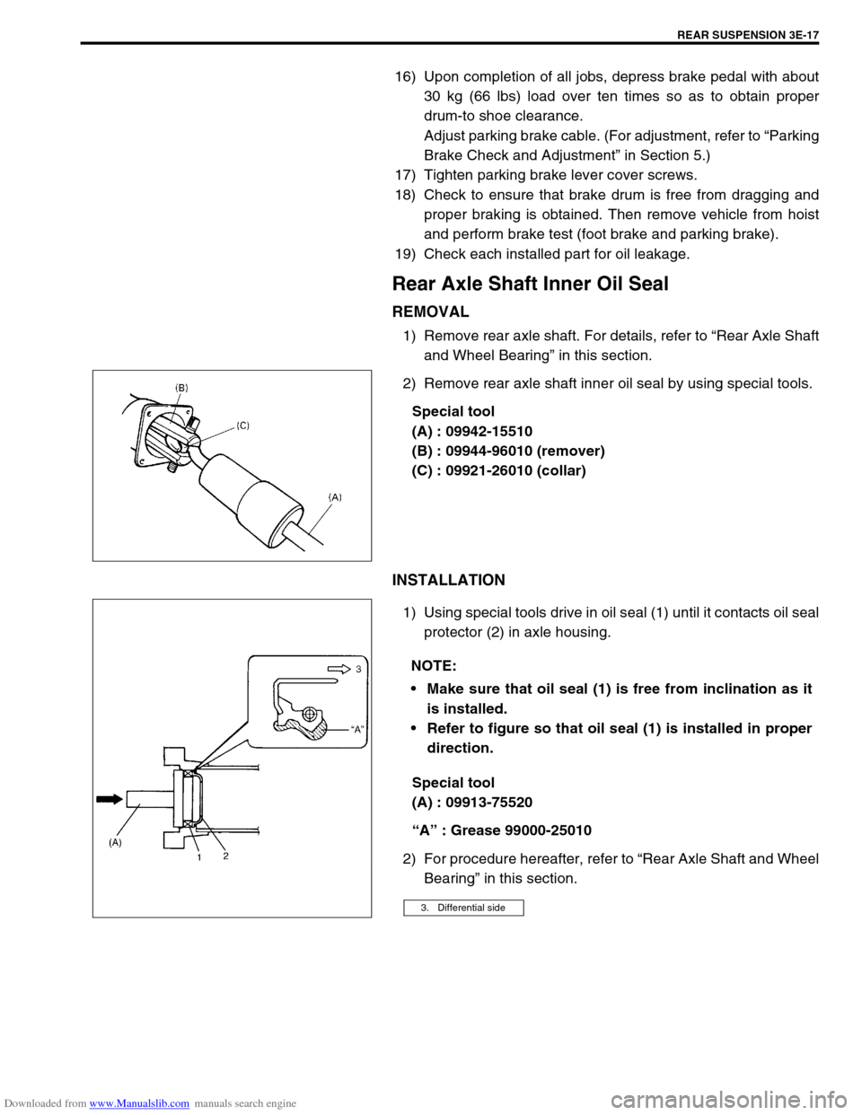
2) Remove rear axle shaft inner oil seal by using special tools.
Special tool
(A) : 09942-15510
(B) : 09944-96010 (remover)
(C) : 09921-26010 (collar)
INSTALLATION
1) Using special tools drive in oil seal (1) until it contacts oil seal
protector (2) in axle housing.
Special tool
(A) : 09913-75520
“A” : Grease 99000-25010
2) For procedure hereafter, refer to “Rear Axle Shaft and Wheel
Bearing” in this section.
NOTE:
Make sure that oil seal (1) is free from inclination as it
is installed.
Refer to figure so that oil seal (1) is installed in proper
direction.
3. Differential side
Page 237 of 687
Downloaded from www.Manualslib.com manuals search engine 3E-18 REAR SUSPENSION
Rear Axle Housing
REMOVAL
1) Hoist vehicle and remove wheels.
2) Remove rear axle shaft, refer to “Rear Axle Shaft and Wheel
Bearing” in this section.
3) Disconnect brake pipe (3) from flexible hose (1) and remove
E-ring (2).
4) Remove brake pipe clamps and pipes from axle housing.
5) For jobs hereafter, support rear axle housing (2) by using
floor jack (1) under axle housing (2).
6) Remove LSPV stay from axle housing (if equipped with
LSPV).
7) Before removing propeller shaft (2), give match marks (1) on
joint flange and propeller shaft (2) as shown.
Remove propeller shaft (2).
8) Remove differential carrier assembly (3).
9) Remove lateral rod (1).
Page 238 of 687
Downloaded from www.Manualslib.com manuals search engine REAR SUSPENSION 3E-19
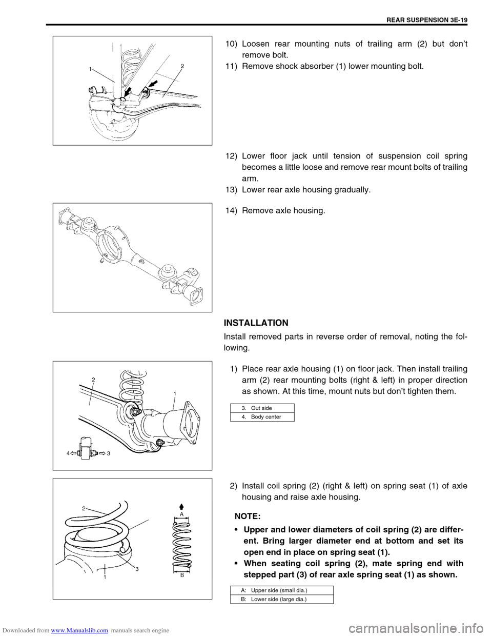
10) Loosen rear mounting nuts of trailing arm (2) but don’t
remove bolt.
11) Remove shock absorber (1) lower mounting bolt.
12) Lower floor jack until tension of suspension coil spring
becomes a little loose and remove rear mount bolts of trailing
arm.
13) Lower rear axle housing gradually.
14) Remove axle housing.
INSTALLATION
Install removed parts in reverse order of removal, noting the fol-
lowing.
1) Place rear axle housing (1) on floor jack. Then install trailing
arm (2) rear mounting bolts (right & left) in proper direction
as shown. At this time, mount nuts but don’t tighten them.
2) Install coil spring (2) (right & left) on spring seat (1) of axle
housing and raise axle housing.
3. Out side
4. Body center
NOTE:
Upper and lower diameters of coil spring (2) are differ-
ent. Bring larger diameter end at bottom and set its
open end in place on spring seat (1).
When seating coil spring (2), mate spring end with
stepped part (3) of rear axle spring seat (1) as shown.
A: Upper side (small dia.)
B: Lower side (large dia.)
Page 239 of 687
Downloaded from www.Manualslib.com manuals search engine 3E-20 REAR SUSPENSION
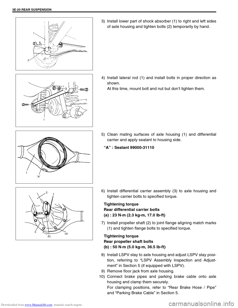
3) Install lower part of shock absorber (1) to right and left sides
of axle housing and tighten bolts (2) temporarily by hand.
4) Install lateral rod (1) and install bolts in proper direction as
shown.
At this time, mount bolt and nut but don’t tighten them.
5) Clean mating surfaces of axle housing (1) and differential
carrier and apply sealant to housing side.
“A” : Sealant 99000-31110
6) Install differential carrier assembly (3) to axle housing and
tighten carrier bolts to specified torque.
Tightening torque
Rear differential carrier bolts
(a) : 23 N·m (2.3 kg-m, 17.0 lb-ft)
7) Install propeller shaft (2) to joint flange aligning match marks
(1) and tighten flange bolts to specified torque.
Tightening torque
Rear propeller shaft bolts
(b) : 50 N·m (5.0 kg-m, 36.5 lb-ft)
8) Install LSPV stay to axle housing and adjust LSPV stay posi-
tion, referring to “LSPV Assembly Inspection and Adjust-
ment” in Section 5 (if equipped with LSPV).
9) Remove floor jack from axle housing.
10) Connect brake pipes and parking brake cable onto axle
housing and clamp them securely.
For clamping positions, refer to “Rear Brake Hose / Pipe”
and “Parking Brake Cable” in Section 5.
Page 241 of 687

Downloaded from www.Manualslib.com manuals search engine 3E-22 REAR SUSPENSION
Tightening Torque Specifications
Required Service Materials
Fastening portionTightening torque
Nm kg-m lb-ft
Shock absorber upper and lower bolt 85 8.5 61.5
Bump stopper 50 5.0 36.5
Lateral rod bolt and nut
90 9.0 65.0
Trailing arm nut (Front and Rear)
Brake back plate nut 23 2.3 17.0
Brake pipe flare nut 16 1.6 11.5
Rear differential carrier bolt 23 2.3 17.0
Rear propeller shaft bolt (Differential case side) 50 5.0 36.5
Rear propeller shaft bolt (Shaft No.3 transfer case side) 33 3.3 24.0
Wheel nut 95 9.5 69.0
Wheel speed sensor bolt and harness clamp bolt 10 1.0 7.5
MaterialRecommended SUZUKI product
(Part Number)Use
Lithium greaseSUZUKI SUPER GREASE A
(99000-25010)Oil seal lip
SealantSUZUKI BOND NO. 1215
(99000-31110)Joint seam of differential carrier and
axle housing
Water tight sealantSEALING COMPOUND 366E
(99000-31090)To apply to mating surfaces of brake
back plate and rear axle.
Gear oilFor gear oil information, refer to “Mainte-
nance Service” in Section 7E of this manual.Differential gear
(Rear axle housing)
Page 257 of 687
Downloaded from www.Manualslib.com manuals search engine 4B-4 PROPELLER SHAFTS
INSTALLATION
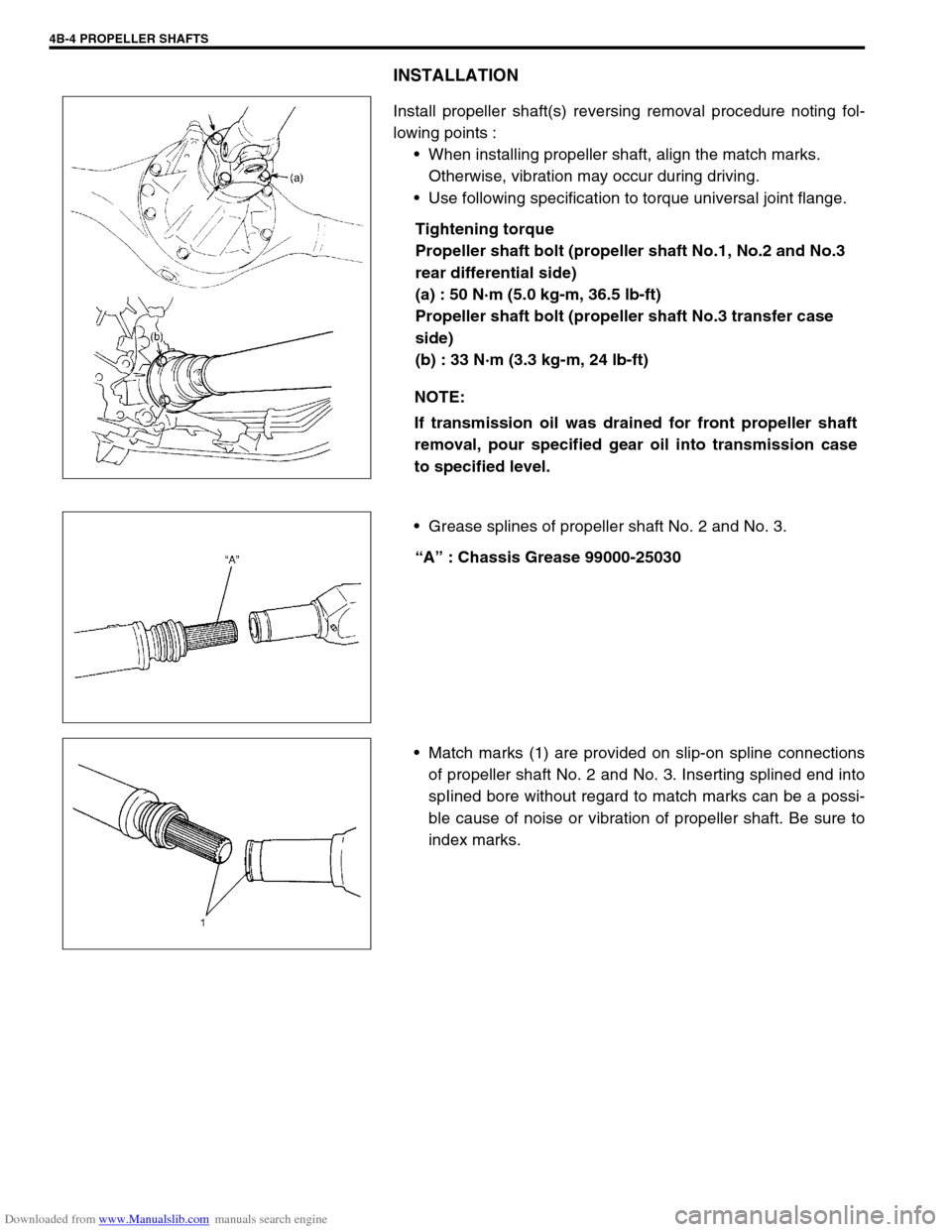
Install propeller shaft(s) reversing removal procedure noting fol-
lowing points :
When installing propeller shaft, align the match marks.
Otherwise, vibration may occur during driving.
Use following specification to torque universal joint flange.
Tightening torque
Propeller shaft bolt (propeller shaft No.1, No.2 and No.3
rear differential side)
(a) : 50 N·m (5.0 kg-m, 36.5 lb-ft)
Propeller shaft bolt (propeller shaft No.3 transfer case
side)
(b) : 33 N·m (3.3 kg-m, 24 lb-ft)
Grease splines of propeller shaft No. 2 and No. 3.
“A” : Chassis Grease 99000-25030
Match marks (1) are provided on slip-on spline connections
of propeller shaft No. 2 and No. 3. Inserting splined end into
spIined bore without regard to match marks can be a possi-
ble cause of noise or vibration of propeller shaft. Be sure to
index marks. NOTE:
If transmission oil was drained for front propeller shaft
removal, pour specified gear oil into transmission case
to specified level.
Page 295 of 687
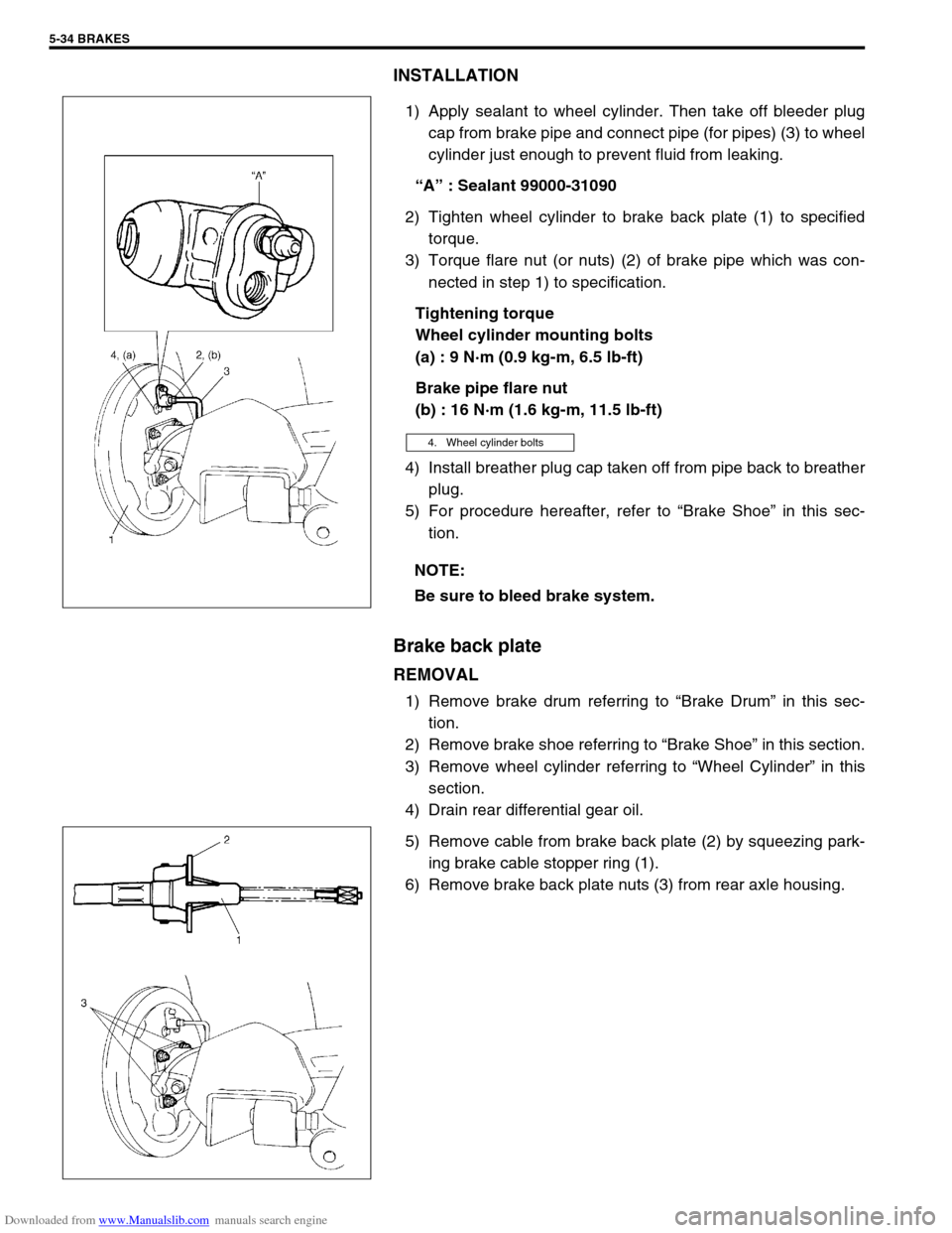
Downloaded from www.Manualslib.com manuals search engine 5-34 BRAKES
INSTALLATION
1) Apply sealant to wheel cylinder. Then take off bleeder plug
cap from brake pipe and connect pipe (for pipes) (3) to wheel
cylinder just enough to prevent fluid from leaking.
“A” : Sealant 99000-31090
2) Tighten wheel cylinder to brake back plate (1) to specified
torque.
3) Torque flare nut (or nuts) (2) of brake pipe which was con-
nected in step 1) to specification.
Tightening torque
Wheel cylinder mounting bolts
(a) : 9 N·m (0.9 kg-m, 6.5 lb-ft)
Brake pipe flare nut
(b) : 16 N·m (1.6 kg-m, 11.5 lb-ft)
4) Install breather plug cap taken off from pipe back to breather
plug.
5) For procedure hereafter, refer to “Brake Shoe” in this sec-
tion.
Brake back plate
REMOVAL
1) Remove brake drum referring to “Brake Drum” in this sec-
tion.
2) Remove brake shoe referring to “Brake Shoe” in this section.
3) Remove wheel cylinder referring to “Wheel Cylinder” in this
section.
4) Drain rear differential gear oil.
5) Remove cable from brake back plate (2) by squeezing park-
ing brake cable stopper ring (1).
6) Remove brake back plate nuts (3) from rear axle housing.
4. Wheel cylinder bolts
NOTE:
Be sure to bleed brake system.
Page 341 of 687

Downloaded from www.Manualslib.com manuals search engine 5E-24 ANTILOCK BRAKE SYSTEM (ABS)
DTC C1041 (DTC 41), DTC C1042 (DTC 42) – Right Front Solenoid Circuit
DTC C1045 (DTC 45), DTC C1046 (DTC 46) – Left Front Solenoid Circuit
DTC C1055 (DTC 55), DTC C1056 (DTC 56) – Rear Solenoid Circuit
DESCRIPTION
The ABS control module monitors the voltage of the terminal of the solenoid circuit constantly with the ignition
switch turned ON. It sets this DTC when the terminal voltage does not become low / high for the ON / OFF com-
mand to the solenoid or the voltage difference between solenoid circuit terminals exceeds the specified value
with the solenoid turned OFF.
INSPECTION
1. ABS hydraulic unit / control module assembly 2-1. Lock position
2. ABS hydraulic unit / control module connector of harness 2-2. Unlock position
Step Action Yes No
1 1) Check solenoid referring to “ABS Hydraulic Unit
Operation Check” in this section.
Is it in good condition?Check terminals “A25” and
“A23” connection.
If connections OK, substitute
a known-good ABS hydraulic
unit / control module assem-
bly and recheck.Go to step 2.
2 1) Ignition switch OFF.
2) Disconnect ABS hydraulic unit / control module
connector.
3) Check for proper connection to ABS hydraulic unit
/ control module connector at terminal “A25”.
4) If OK, then measure voltage between terminal
“A25” of module connector and body ground.
Is it 10 – 14 V?Substitute a known-good
ABS hydraulic unit / control
module assembly and
recheck.“W/Bl” circuit
open.