Page 3173 of 4555
EXHAUST SYSTEM
EX-3
C
D
E
F
G
H
I
J
K
L
MA
EX
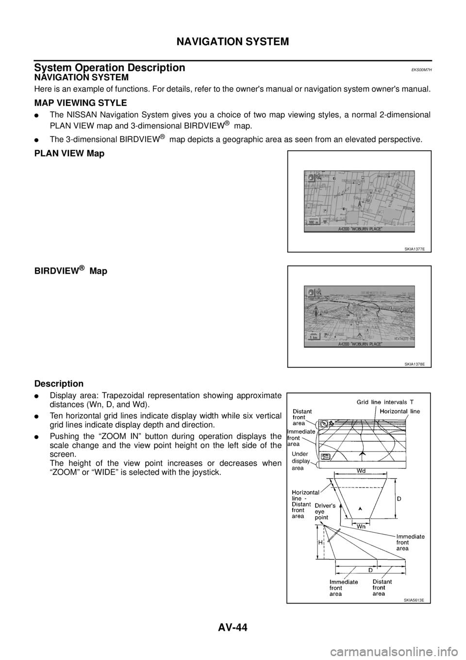
*: In regard to the notation of torque in the figure, “NEW” shows an ISO standard, “OLD” shows a conventional standard, and the mea-
surements of hexagonal width across flats are in parentheses.
YD22DDTi
*: In regard to the notation of torque in the figure, “NEW” shows an ISO standard, “OLD” shows a conventional standard, and the mea-
surements of hexagonal width across flats are in parentheses.
REMOVAL
Separate each connection as necessity.
INSTALLATION
Note the following, and install in the reverse order of removal.
CAUTION:
�Always replace exhaust gaskets and seal bearings with new ones when reassembling.
�If insulator is badly deformed, repair or replace it. If deposits such as mud pile up on insulator,
remove them.
�When installing insulator avoid large gaps or interference between insulator and each exhaust
pipe.
�Remove deposits from the sealing surface of each connection. Connect them securely to avoid
gas leakage.
1. Main muffler 2. Mounting rubber 3. Spring
4. Gasket 5. Three way catalyst 6. Exhaust front tube
7. Seal bearing 8. Mounting rubber bracket 9. Mounting bracket
10. Exhaust center tube
PBIC3628E
1. Main muffler 2. Mounting rubber 3. Spring
4. Ring gasket 5. Exhaust tube 6. Exhaust front tube
7. Mounting bracket 8. Mounting rubber bracket 9. Mounting bracket
10. Exhaust center tube 11. Gasket 12. Seal bearing
Page 3386 of 4555
AV-44
NAVIGATION SYSTEM
System Operation DescriptionEKS00M7H
NAVIGATION SYSTEM
Here is an example of functions. For details, refer to the owner's manual or navigation system owner's manual.
MAP VIEWING STYLE
�The NISSAN Navigation System gives you a choice of two map viewing styles, a normal 2-dimensional
PLAN VIEW map and 3-dimensional BIRDVIEW
® map.
�The 3-dimensional BIRDVIEW® map depicts a geographic area as seen from an elevated perspective.
PLAN VIEW Map
BIRDVIEW
® Map
Description
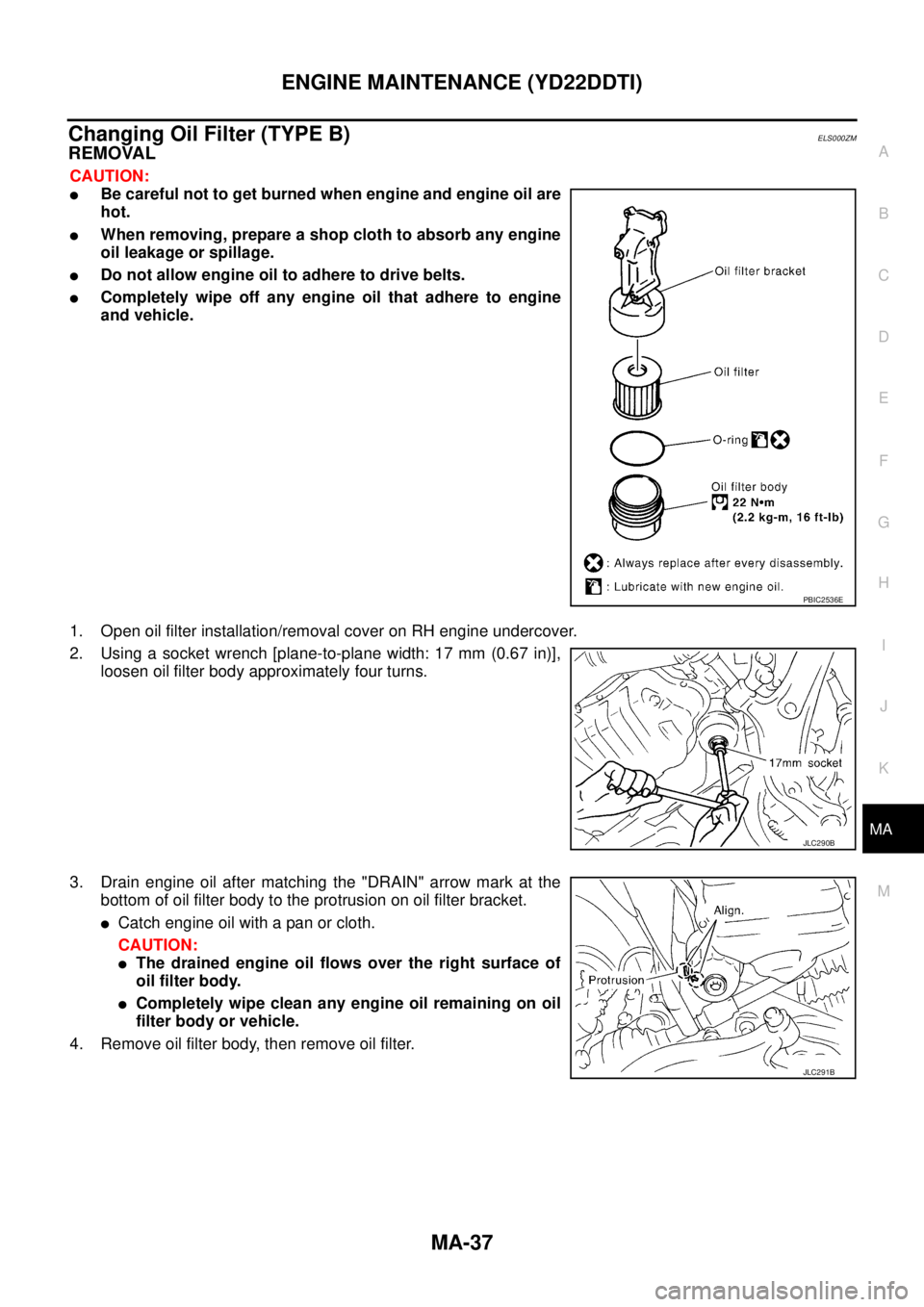
�Display area: Trapezoidal representation showing approximate
distances (Wn, D, and Wd).
�Ten horizontal grid lines indicate display width while six vertical
grid lines indicate display depth and direction.
�Pushing the “ZOOM IN” button during operation displays the
scale change and the view point height on the left side of the
screen.
The height of the view point increases or decreases when
“ZOOM” or “WIDE” is selected with the joystick.
SKIA1377E
SKIA1378E
SKIA5613E
Page 4533 of 4555
ENGINE MAINTENANCE (YD22DDTI)
MA-37
C
D
E
F
G
H
I
J
K
MA
B
MA
Changing Oil Filter (TYPE B)ELS000ZM
REMOVAL
CAUTION:
�Be careful not to get burned when engine and engine oil are
hot.
�When removing, prepare a shop cloth to absorb any engine
oil leakage or spillage.
�Do not allow engine oil to adhere to drive belts.
�Completely wipe off any engine oil that adhere to engine
and vehicle.
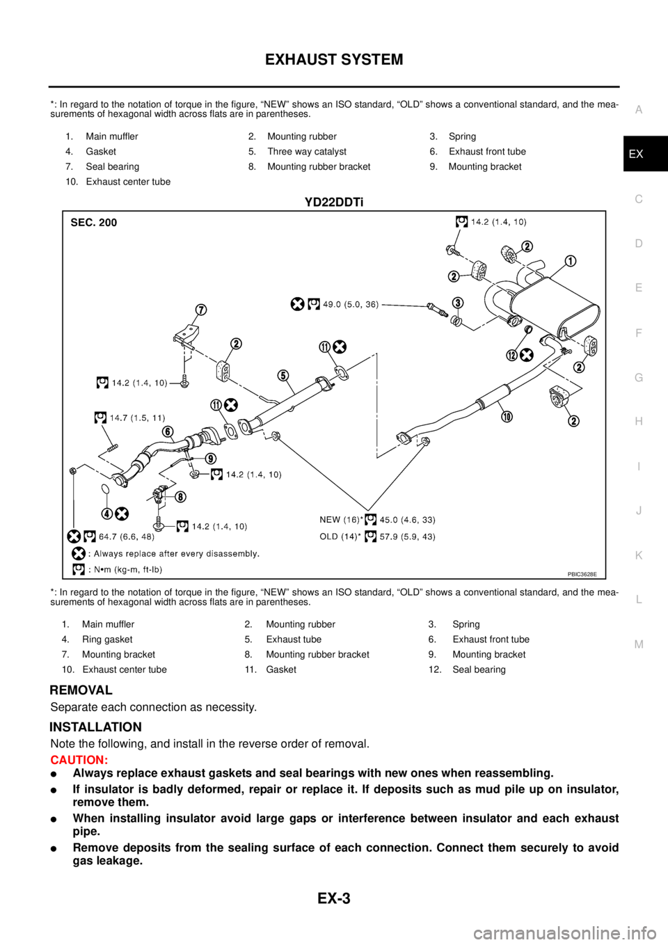
1. Open oil filter installation/removal cover on RH engine undercover.
2. Using a socket wrench [plane-to-plane width: 17 mm (0.67 in)],
loosen oil filter body approximately four turns.
3. Drain engine oil after matching the "DRAIN" arrow mark at the
bottom of oil filter body to the protrusion on oil filter bracket.
�Catch engine oil with a pan or cloth.
CAUTION:
�The drained engine oil flows over the right surface of
oil filter body.
�Completely wipe clean any engine oil remaining on oil
filter body or vehicle.
4. Remove oil filter body, then remove oil filter.
PBIC2536E
JLC290B
JLC291B