Page 3732 of 4555

GW-18
REAR WINDOW DEFOGGER
With power and ground supplied, the rear window defogger and door mirror defogger filaments heat and defog
the rear window and door mirror.
When the system is activated, the rear window defogger indicator illuminates in the rear window defogger
switch.
Power is supplied
�through rear window defogger relay terminal 3 (without door mirror defogger or side air bag) or
�through rear window defogger relay terminal 5 (with door mirror defogger or side air bag)
�to rear window defogger switch terminal 3 (without auto A/C) or
�to A/C auto amp, terminal 23 (with auto A/C).
System Description / RHD ModelsEIS008O7
The rear window defogger system is controlled by time control unit. The rear window defogger operates only
for approximately 15 minutes.
Power is supplied at all times
�through 20A fuse (No.25, located in the fuse and fusible link box) and
�to rear window defogger relay terminal 3 (with side air bag) or
�to rear window defogger relay terminal 5 (without side air bag).
With the ignition switch in the ON or START position, power is supplied
�through 10A fuse [No.5, located in the fuse block (J/B)]
�to rear window defogger relay terminal 1 and
�to time control unit terminal 17.
Ground is supplied
�to rear window defogger switch terminals 2 and 4 (without auto A/C) or
�to A/C auto amp. Terminal 3 (with auto A/C)
�through body ground M27 and M70.
When the rear window defogger switch is turned ON, ground is supplied
�to time control unit terminal 35
�through rear window defogger switch terminal 1 (without auto A/C) or
�through A/C auto amp, terminal 22 (with auto A/C).
Terminal 27 of the time control unit then supplies ground to the rear window defogger relay terminal 2.
With power and ground supplied, the rear window defogger relay is energized.
Power is supplied
�through rear window defogger terminal 3 (without side air bag) or
�through rear window defogger terminal 5 (with side air bag)
�to the rear window defogger.
The rear window defogger and door mirror defogger has an independent ground.
With power and ground supplied, the rear window defogger and door mirror defogger filaments heat and defog
the rear window and door mirror.
When the system is activated, the rear window defogger indicator illuminates in the rear window defogger
switch.
Power is supplied
�through rear window defogger relay terminal 3 (without side air bag) or
�through rear window defogger relay terminal 5 (with side air bag)
�to rear window defogger switch terminal 3 (without auto A/C) or
�to A/C auto amp, terminal 23 (with auto A/C).
Page 3754 of 4555
GW-40
POWER WINDOW SYSTEM
POWER WINDOW SYSTEMPFP:25401
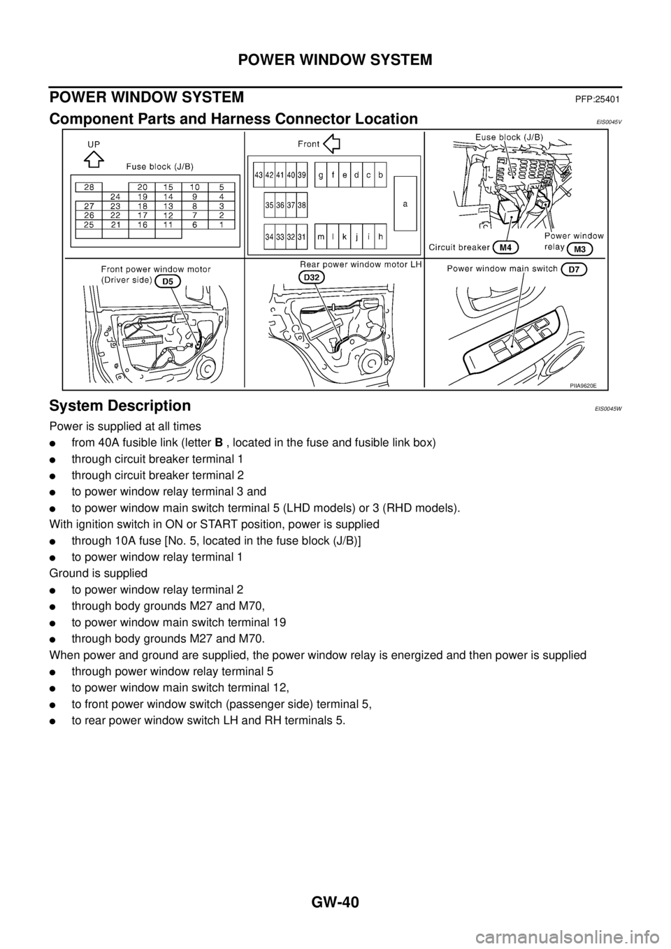
Component Parts and Harness Connector LocationEIS0045V
System DescriptionEIS0045W
Power is supplied at all times
�from 40A fusible link (letter B , located in the fuse and fusible link box)
�through circuit breaker terminal 1
�through circuit breaker terminal 2
�to power window relay terminal 3 and
�to power window main switch terminal 5 (LHD models) or 3 (RHD models).
With ignition switch in ON or START position, power is supplied
�through 10A fuse [No. 5, located in the fuse block (J/B)]
�to power window relay terminal 1
Ground is supplied
�to power window relay terminal 2
�through body grounds M27 and M70,
�to power window main switch terminal 19
�through body grounds M27 and M70.
When power and ground are supplied, the power window relay is energized and then power is supplied
�through power window relay terminal 5
�to power window main switch terminal 12,
�to front power window switch (passenger side) terminal 5,
�to rear power window switch LH and RH terminals 5.
PIIA9620E
Page 3773 of 4555
![NISSAN X-TRAIL 2005 Service Repair Manual POWER WINDOW SYSTEM
GW-59
C
D
E
F
G
H
J
K
L
MA
B
GW
Power Window Relay Power Supply and Ground Circuit CheckEIS008BB
1. CHECK FUSE
�Check 10A fuse [No. 5, located in fuse block (J/B)]
�Check 40A fus NISSAN X-TRAIL 2005 Service Repair Manual POWER WINDOW SYSTEM
GW-59
C
D
E
F
G
H
J
K
L
MA
B
GW
Power Window Relay Power Supply and Ground Circuit CheckEIS008BB
1. CHECK FUSE
�Check 10A fuse [No. 5, located in fuse block (J/B)]
�Check 40A fus](/manual-img/5/57403/w960_57403-3772.png)
POWER WINDOW SYSTEM
GW-59
C
D
E
F
G
H
J
K
L
MA
B
GW
Power Window Relay Power Supply and Ground Circuit CheckEIS008BB
1. CHECK FUSE
�Check 10A fuse [No. 5, located in fuse block (J/B)]
�Check 40A fusible link (litter B , located in the fuse and fusible link box.)
NOTE:
Refer to GW-40, "
Component Parts and Harness Connector Location" .
OK or NG
OK >> GO TO 2.
NG >> If fuse is blown out, be sure to eliminate cause of malfunction before installing new fuse. Refer to
PG-2, "
POWER SUPPLY ROUTING" .
2. CHECK POWER WINDOW RELAY POWER SUPPLY
1. Turn ignition switch OFF.
2. Remove power window relay.
3. Turn ignition switch ON.
4. Check voltage between power window relay connector M3 ter-
minal 1, 3 and ground.
OK or NG
OK >> GO TO 3.
NG >> Check power window relay power supply circuit for open
or short.
3. CHECK POWER WINDOW RELAY GROUND
1. Turn ignition switch OFF.
2. Check continuity between power window relay connector M3
terminal 2 and ground.
OK or NG
OK >> GO TO 4.
NG >> Check power window relay ground circuit for open or
short.
4. CHECK POWER WINDOW RELAY
Check continuity between power window relay terminal 3 and 5.
OK or NG
OK >> Check the condition of the harness and the connector.
NG >> Replace power window relay.1 (G) - Ground : Battery voltage
3 (W) - Ground : Battery voltage
PIIA9574E
2 (B) - Ground : Continuity should exist.
PIIA9575E
Terminal Condition Continuity
3512V direct current supply between
terminals 1 and 2Ye s
No current supply No
PIIA2636E
Page 3877 of 4555
INSTRUMENT PANEL ASSEMBLY
IP-11
C
D
E
F
G
H
J
K
L
MA
B
IP
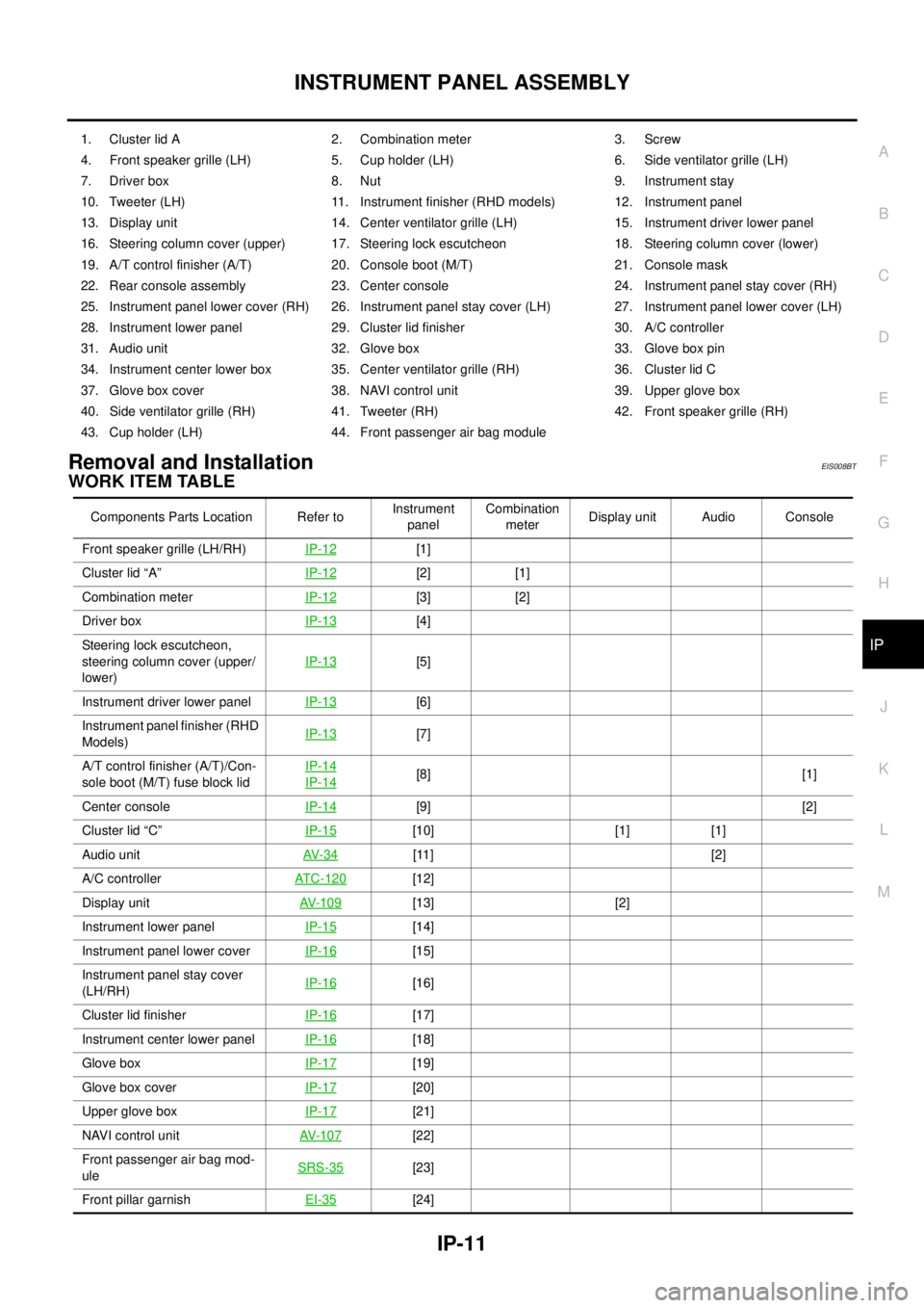
Removal and InstallationEIS008BT
WORK ITEM TABLE
1. Cluster lid A 2. Combination meter 3. Screw
4. Front speaker grille (LH) 5. Cup holder (LH) 6. Side ventilator grille (LH)
7. Driver box 8. Nut 9. Instrument stay
10. Tweeter (LH) 11. Instrument finisher (RHD models) 12. Instrument panel
13. Display unit 14. Center ventilator grille (LH) 15. Instrument driver lower panel
16. Steering column cover (upper) 17. Steering lock escutcheon 18. Steering column cover (lower)
19. A/T control finisher (A/T) 20. Console boot (M/T) 21. Console mask
22. Rear console assembly 23. Center console 24. Instrument panel stay cover (RH)
25. Instrument panel lower cover (RH) 26. Instrument panel stay cover (LH) 27. Instrument panel lower cover (LH)
28. Instrument lower panel 29. Cluster lid finisher 30. A/C controller
31. Audio unit 32. Glove box 33. Glove box pin
34. Instrument center lower box 35. Center ventilator grille (RH) 36. Cluster lid C
37. Glove box cover 38. NAVI control unit 39. Upper glove box
40. Side ventilator grille (RH) 41. Tweeter (RH) 42. Front speaker grille (RH)
43. Cup holder (LH) 44. Front passenger air bag module
Components Parts Location Refer toInstrument
panelCombination
meterDisplay unit Audio Console
Front speaker grille (LH/RH)IP-12
[1]
Cluster lid “A”IP-12
[2] [1]
Combination meterIP-12
[3] [2]
Driver boxIP-13
[4]
Steering lock escutcheon,
steering column cover (upper/
lower)IP-13
[5]
Instrument driver lower panel IP-13
[6]
Instrument panel finisher (RHD
Models)IP-13
[7]
A/T control finisher (A/T)/Con-
sole boot (M/T) fuse block lidIP-14
IP-14[8] [1]
Center consoleIP-14
[9] [2]
Cluster lid “C”IP-15
[10] [1] [1]
Audio unitAV- 3 4
[11] [2]
A/C controllerATC-120
[12]
Display unitAV- 1 0 9
[13] [2]
Instrument lower panelIP-15
[14]
Instrument panel lower cover IP-16
[15]
Instrument panel stay cover
(LH/RH)IP-16
[16]
Cluster lid finisherIP-16
[17]
Instrument center lower panelIP-16
[18]
Glove boxIP-17
[19]
Glove box coverIP-17
[20]
Upper glove boxIP-17
[21]
NAVI control unitAV- 1 0 7
[22]
Front passenger air bag mod-
uleSRS-35
[23]
Front pillar garnishEI-35
[24]
Page 3879 of 4555
INSTRUMENT PANEL ASSEMBLY
IP-13
C
D
E
F
G
H
J
K
L
MA
B
IP
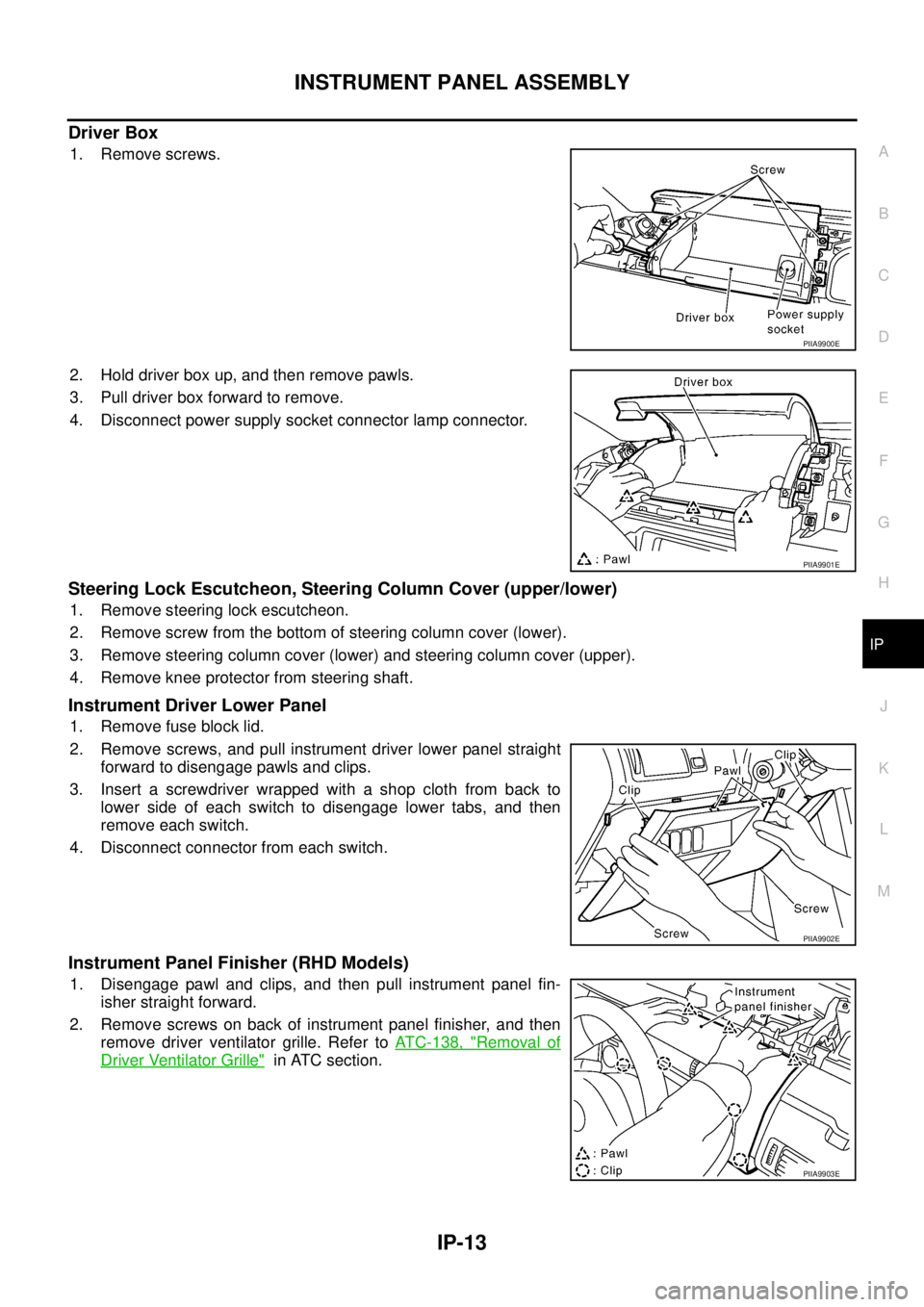
Driver Box
1. Remove screws.
2. Hold driver box up, and then remove pawls.
3. Pull driver box forward to remove.
4. Disconnect power supply socket connector lamp connector.
Steering Lock Escutcheon, Steering Column Cover (upper/lower)
1. Remove steering lock escutcheon.
2. Remove screw from the bottom of steering column cover (lower).
3. Remove steering column cover (lower) and steering column cover (upper).
4. Remove knee protector from steering shaft.
Instrument Driver Lower Panel
1. Remove fuse block lid.
2. Remove screws, and pull instrument driver lower panel straight
forward to disengage pawls and clips.
3. Insert a screwdriver wrapped with a shop cloth from back to
lower side of each switch to disengage lower tabs, and then
remove each switch.
4. Disconnect connector from each switch.
Instrument Panel Finisher (RHD Models)
1. Disengage pawl and clips, and then pull instrument panel fin-
isher straight forward.
2. Remove screws on back of instrument panel finisher, and then
remove driver ventilator grille. Refer to ATC-138, "
Removal of
Driver Ventilator Grille" in ATC section.
PIIA9900E
PIIA9901E
PIIA9902E
PIIA9903E
Page 3936 of 4555
MTC-12
TROUBLE DIAGNOSIS
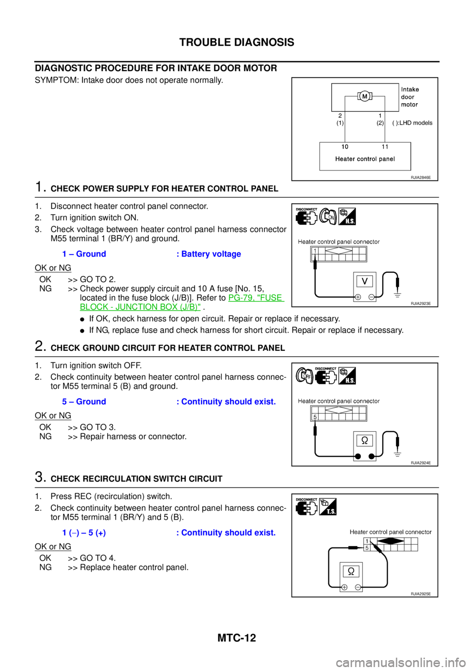
DIAGNOSTIC PROCEDURE FOR INTAKE DOOR MOTOR
SYMPTOM: Intake door does not operate normally.
1. CHECK POWER SUPPLY FOR HEATER CONTROL PANEL
1. Disconnect heater control panel connector.
2. Turn ignition switch ON.
3. Check voltage between heater control panel harness connector
M55 terminal 1 (BR/Y) and ground.
OK or NG
OK >> GO TO 2.
NG >> Check power supply circuit and 10 A fuse [No. 15,
located in the fuse block (J/B)]. Refer to PG-79, "
FUSE
BLOCK - JUNCTION BOX (J/B)" .
�If OK, check harness for open circuit. Repair or replace if necessary.
�If NG, replace fuse and check harness for short circuit. Repair or replace if necessary.
2. CHECK GROUND CIRCUIT FOR HEATER CONTROL PANEL
1. Turn ignition switch OFF.
2. Check continuity between heater control panel harness connec-
tor M55 terminal 5 (B) and ground.
OK or NG
OK >> GO TO 3.
NG >> Repair harness or connector.
3. CHECK RECIRCULATION SWITCH CIRCUIT
1. Press REC (recirculation) switch.
2. Check continuity between heater control panel harness connec-
tor M55 terminal 1 (BR/Y) and 5 (B).
OK or NG
OK >> GO TO 4.
NG >> Replace heater control panel.
RJIA2846E
1 – Ground : Battery voltage
RJIA2923E
5 – Ground : Continuity should exist.
RJIA2924E
1 (−) – 5 (+) : Continuity should exist.
RJIA2925E
Page 3940 of 4555
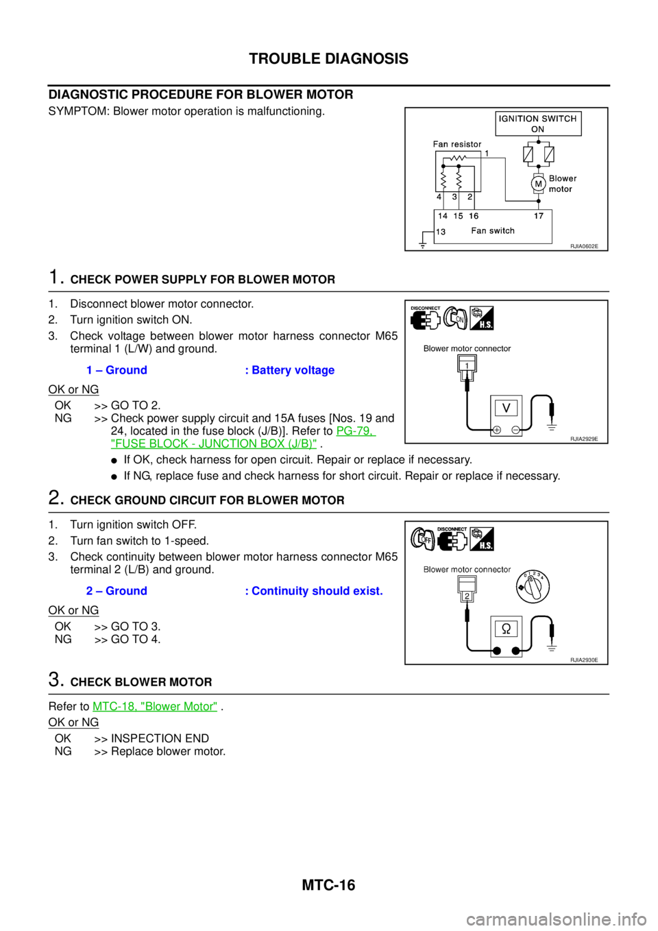
MTC-16
TROUBLE DIAGNOSIS
DIAGNOSTIC PROCEDURE FOR BLOWER MOTOR
SYMPTOM: Blower motor operation is malfunctioning.
1. CHECK POWER SUPPLY FOR BLOWER MOTOR
1. Disconnect blower motor connector.
2. Turn ignition switch ON.
3. Check voltage between blower motor harness connector M65
terminal 1 (L/W) and ground.
OK or NG
OK >> GO TO 2.
NG >> Check power supply circuit and 15A fuses [Nos. 19 and
24, located in the fuse block (J/B)]. Refer to PG-79,
"FUSE BLOCK - JUNCTION BOX (J/B)" .
�If OK, check harness for open circuit. Repair or replace if necessary.
�If NG, replace fuse and check harness for short circuit. Repair or replace if necessary.
2. CHECK GROUND CIRCUIT FOR BLOWER MOTOR
1. Turn ignition switch OFF.
2. Turn fan switch to 1-speed.
3. Check continuity between blower motor harness connector M65
terminal 2 (L/B) and ground.
OK or NG
OK >> GO TO 3.
NG >> GO TO 4.
3. CHECK BLOWER MOTOR
Refer to MTC-18, "
Blower Motor" .
OK or NG
OK >> INSPECTION END
NG >> Replace blower motor.
RJIA0602E
1 – Ground : Battery voltage
RJIA2929E
2 – Ground : Continuity should exist.
RJIA2930E
Page 3949 of 4555
BLOWER FAN RESISTOR
MTC-25
C
D
E
F
G
H
I
K
L
MA
B
MTC
BLOWER FAN RESISTORPFP:27150
Removal and InstallationEJS004HE
REMOVAL
1. Remove glove box cover. Refer to IP-11, "Removal and Installation" .
2. Remove mounting screws, and then remove fan resistor.
CAUTION:
Do not repair the thermal fuse of the fan resistor.
INSTALLATION
Installation is basically the reverse order of removal.
RJIA0093E