Page 715 of 4555
![NISSAN X-TRAIL 2005 Service Repair Manual DTC P1124, P1126 THROTTLE CONTROL MOTOR RELAY
EC-311
[QR (WITH EURO-OBD)]
C
D
E
F
G
H
I
J
K
L
MA
EC
Specification data are reference values and are measured between each terminal and ground.
CAUTION](/manual-img/5/57403/w960_57403-714.png "NISSAN X-TRAIL 2005 Service Repair Manual DTC P1124, P1126 THROTTLE CONTROL MOTOR RELAY
EC-311
[QR (WITH EURO-OBD)]
C
D
E
F
G
H
I
J
K
L
MA
EC
Specification data are reference values and are measured between each terminal and ground.
CAUTION")
DTC P1124, P1126 THROTTLE CONTROL MOTOR RELAY
EC-311
[QR (WITH EURO-OBD)]
C
D
E
F
G
H
I
J
K
L
MA
EC
Specification data are reference values and are measured between each terminal and ground.
CAUTION:
Do not use ECM ground terminals when measuring input/output voltage. Doing so may result in dam-
age to the ECM's transistor. Use a ground other than ECM terminals, such as the ground.
Diagnostic ProcedureEBS010RU
1. CHECK THROTTLE CONTROL MOTOR RELAY POWER SUPPLY CIRCUIT
1. Turn ignition switch OFF.
2. Disconnect throttle control motor relay.
3. Check voltage between throttle control motor relay terminals 2, 5
and ground.
OK or NG
OK >> GO TO 3.
NG >> GO TO 2.
2. DETECT MALFUNCTIONING PART
Check the following.
�15A fuse
�Harness for open or short between throttle control motor relay and battery
>> Repair or replace harness or connectors.
TERMI-
NAL
NO.WIRE
COLORITEM CONDITION DATA (DC Voltage)
3W/BThrottle control motor
relay power supply[Ignition switch: ON]BATTERY VOLTAGE
(11 - 14V)
104 W/BThrottle control motor
relay[Ignition switch: OFF]BATTERY VOLTAGE
(11 - 14V)
[Ignition switch: ON]0 - 1.0V
PBIB1972E
Voltage: Battery voltage
PBIB0575E
Page 767 of 4555
DTC P1217 ENGINE OVER TEMPERATURE
EC-363
[QR (WITH EURO-OBD)]
C
D
E
F
G
H
I
J
K
L
MA
EC
PROCEDURE A
1. CHECK COOLING FAN POWER SUPPLY CIRCUIT
1. Turn ignition switch OFF.
2. Disconnect cooling fan relay-1.
3. Turn ignition switch ON.
4. Check voltage between cooling fan relay-1 terminals 1, 5, 7 and
ground with CONSULT-II or tester.
OK or NG
OK >> GO TO 3.
NG >> GO TO 2.
2. DETECT MALFUNCTIONING PART
Check the following.
�Fuse block (J/B) connector E103
�10A fuse
�40A fusible links
�Harness for open or short between cooling fan relay-1 and fuse
�Harness for open or short between cooling fan relay-1 and battery
>> Repair open circuit or short to ground or short to power in harness or connectors.
PBIB1972E
Voltage: Battery voltage
PBIB0577E
Page 769 of 4555
![NISSAN X-TRAIL 2005 Service Repair Manual DTC P1217 ENGINE OVER TEMPERATURE
EC-365
[QR (WITH EURO-OBD)]
C
D
E
F
G
H
I
J
K
L
MA
EC
8. CHECK INTERMITTENT INCIDENT
Perform EC-124, "
TROUBLE DIAGNOSIS FOR INTERMITTENT INCIDENT" .
>>INSPECTION E](/manual-img/5/57403/w960_57403-768.png "NISSAN X-TRAIL 2005 Service Repair Manual DTC P1217 ENGINE OVER TEMPERATURE
EC-365
[QR (WITH EURO-OBD)]
C
D
E
F
G
H
I
J
K
L
MA
EC
8. CHECK INTERMITTENT INCIDENT
Perform EC-124, \"
TROUBLE DIAGNOSIS FOR INTERMITTENT INCIDENT\" .
>>INSPECTION E")
DTC P1217 ENGINE OVER TEMPERATURE
EC-365
[QR (WITH EURO-OBD)]
C
D
E
F
G
H
I
J
K
L
MA
EC
8. CHECK INTERMITTENT INCIDENT
Perform EC-124, "
TROUBLE DIAGNOSIS FOR INTERMITTENT INCIDENT" .
>>INSPECTION END
PROCEDURE B
1. CHECK COOLING FAN POWER SUPPLY CIRCUIT
1. Turn ignition switch OFF.
2. Disconnect cooling fan relay-3.
3. Turn ignition switch ON.
4. Check voltage between cooling fan relay-3 terminals 1, 3 and
ground with CONSULT-II or tester.
OK or NG
OK >> GO TO 3.
NG >> GO TO 2.
2. DETECT MALFUNCTIONING PART
Check the following.
�Harness for open or short between cooling fan relay-3 and fuse
�Harness for open or short between cooling fan relay-3 and battery
>> Repair open circuit or short to ground or short to power in harness or connectors.
3. CHECK COOLING FAN MOTORS CONTROL CIRCUIT FOR OPEN AND SHORT
1. Turn ignition switch OFF.
2. Disconnect cooling fan motor-2 harness connector.
3. Check harness continuity between cooling fan relay-3 terminal 5
and cooling fan motor-2 terminal 2, cooling fan motor-2 terminal
3 and cooling fan relay-3 terminal 6, cooling fan relay-3 terminal
7 and ground.
4. Also check harness for short to ground and short to power.
OK or NG
OK >> GO TO 4.
NG >> Repair open circuit or short to ground or short to power
in harness or connectors.
PBIB1972E
Voltage: Battery voltage
PBIB0251E
Continuity should exist.
PBIB0504E
Page 796 of 4555
![NISSAN X-TRAIL 2005 Service Repair Manual EC-392
[QR (WITH EURO-OBD)]
DTC P1572 ASCD BRAKE SWITCH
4. DETECT MALFUNCTIONING PART
Check the following.
�Fuse block (J/B) connector M2
�10A fuse
�Harness for open or short between ASCD brake swit](/manual-img/5/57403/w960_57403-795.png "NISSAN X-TRAIL 2005 Service Repair Manual EC-392
[QR (WITH EURO-OBD)]
DTC P1572 ASCD BRAKE SWITCH
4. DETECT MALFUNCTIONING PART
Check the following.
�Fuse block (J/B) connector M2
�10A fuse
�Harness for open or short between ASCD brake swit")
EC-392
[QR (WITH EURO-OBD)]
DTC P1572 ASCD BRAKE SWITCH
4. DETECT MALFUNCTIONING PART
Check the following.
�Fuse block (J/B) connector M2
�10A fuse
�Harness for open or short between ASCD brake switch and fuse
>> Repair open circuit or short to ground or short to power in harness or connectors.
5. CHECK ASCD CLUTCH SWITCH POWER SUPPLY CIRCUIT
1. Turn ignition switch OFF.
2. Disconnect ASCD clutch switch harness connector.
3. Turn ignition switch ON.
4. Check voltage between ASCD clutch switch terminal 1 and
ground with CONSULT-II or tester.
OK or NG
OK >> GO TO 7.
NG >> GO TO 6.
6. DETECT MALFUNCTIONING PART
Check the following.
�Fuse block (J/B) connector M2
�10A fuse
�Harness for open or short between ASCD clutch switch and fuse
>> Repair open circuit or short to ground or short to power in harness or connectors.
7. CHECK ASCD BRAKE SWITCH INPUT SIGNAL CIRCUIT FOR OPEN AND SHORT
1. Turn ignition switch OFF.
2. Check harness continuity between ASCD clutch switch terminal 2 and ASCD brake switch terminal 1.
Refer to Wiring Diagram.
3. Also check harness for short to ground and short to power.
OK or NG
OK >> GO TO 8.
NG >> Repair open circuit or short to ground or short to power in harness or connectors.
8. CHECK ASCD CLUTCH SWITCH
Refer to EC-395, "
Component Inspection"
OK or NG
OK >> GO TO 15.
NG >> Replace ASCD clutch switch.Voltage: Battery voltage
PBIB0799E
Continuity should exist.
Page 798 of 4555
EC-394
[QR (WITH EURO-OBD)]
DTC P1572 ASCD BRAKE SWITCH
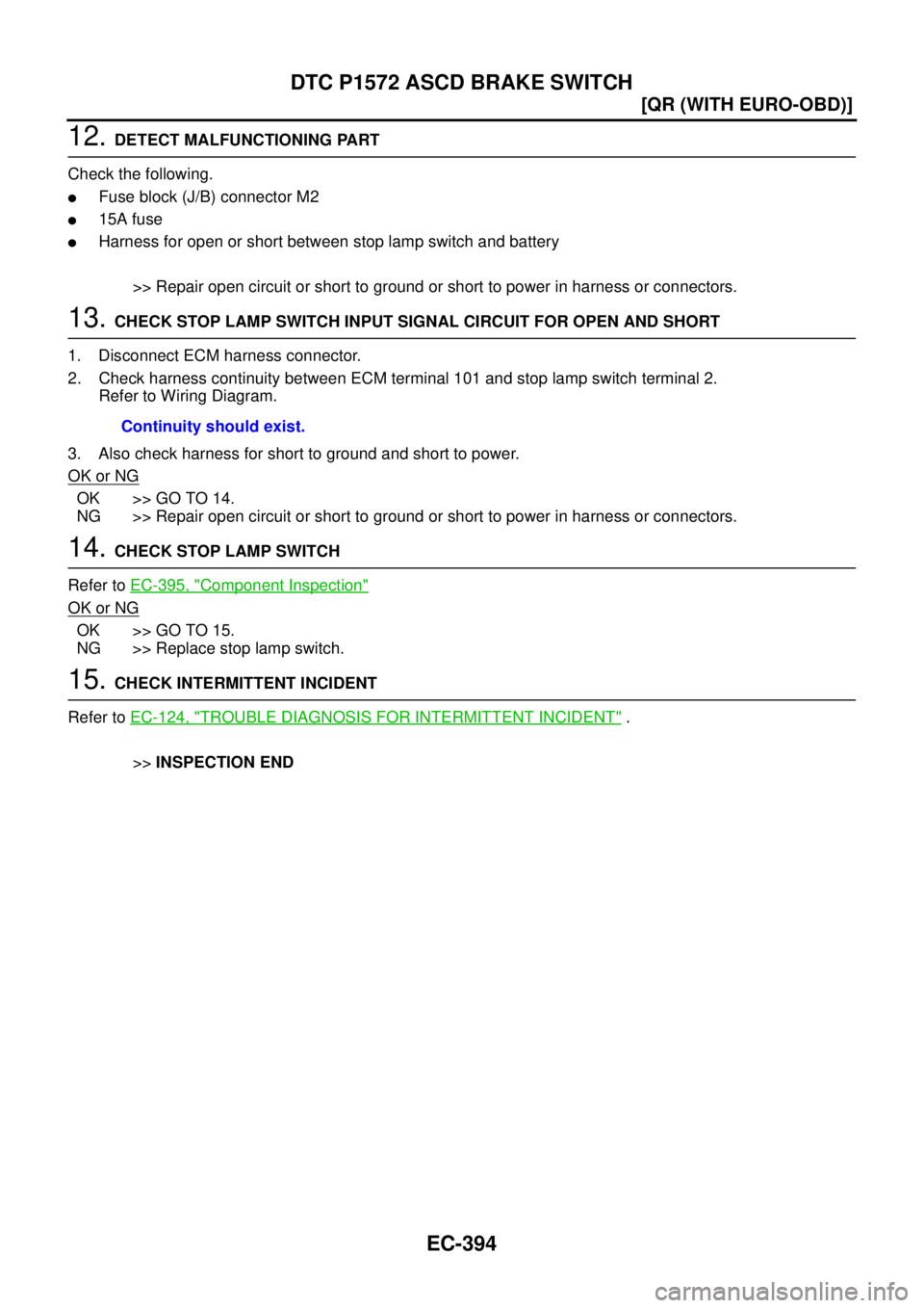
12. DETECT MALFUNCTIONING PART
Check the following.
�Fuse block (J/B) connector M2
�15A fuse
�Harness for open or short between stop lamp switch and battery
>> Repair open circuit or short to ground or short to power in harness or connectors.
13. CHECK STOP LAMP SWITCH INPUT SIGNAL CIRCUIT FOR OPEN AND SHORT
1. Disconnect ECM harness connector.
2. Check harness continuity between ECM terminal 101 and stop lamp switch terminal 2.
Refer to Wiring Diagram.
3. Also check harness for short to ground and short to power.
OK or NG
OK >> GO TO 14.
NG >> Repair open circuit or short to ground or short to power in harness or connectors.
14. CHECK STOP LAMP SWITCH
Refer to EC-395, "
Component Inspection"
OK or NG
OK >> GO TO 15.
NG >> Replace stop lamp switch.
15. CHECK INTERMITTENT INCIDENT
Refer to EC-124, "
TROUBLE DIAGNOSIS FOR INTERMITTENT INCIDENT" .
>>INSPECTION END Continuity should exist.
Page 812 of 4555
![NISSAN X-TRAIL 2005 Service Repair Manual EC-408
[QR (WITH EURO-OBD)]
DTC P1805 BRAKE SWITCH
3. DETECT MALFUNCTIONING PART
Check the following.
�15A fuse
�Fuse block (J/B) connector M2
�Harness for open and short between stop lamp switch an](/manual-img/5/57403/w960_57403-811.png "NISSAN X-TRAIL 2005 Service Repair Manual EC-408
[QR (WITH EURO-OBD)]
DTC P1805 BRAKE SWITCH
3. DETECT MALFUNCTIONING PART
Check the following.
�15A fuse
�Fuse block (J/B) connector M2
�Harness for open and short between stop lamp switch an")
EC-408
[QR (WITH EURO-OBD)]
DTC P1805 BRAKE SWITCH
3. DETECT MALFUNCTIONING PART
Check the following.
�15A fuse
�Fuse block (J/B) connector M2
�Harness for open and short between stop lamp switch and battery
>> Repair open circuit or short to ground or short to power in harness or connectors.
4. CHECK STOP LAMP SWITCH INPUT SIGNAL CIRCUIT FOR OPEN AND SHORT
1. Disconnect ECM harness connector.
2. Check harness continuity between stop lamp switch terminal 2 and ECM terminal 101.
Refer to Wiring Diagram.
3. Also check harness for short to ground and short to power.
OK or NG
OK >> GO TO 5.
NG >> Repair open circuit or short to ground or short to power in harness or connectors.
5. CHECK STOP LAMP SWITCH
Refer to EC-408, "
Component Inspection" .
OK or NG
OK >> GO TO 6.
NG >> Replace stop lamp switch.
6. CHECK INTERMITTENT INCIDENT
Refer to EC-124, "
TROUBLE DIAGNOSIS FOR INTERMITTENT INCIDENT" .
>>INSPECTION END
Component InspectionEBS01FF8
STOP LAMP SWITCH
1. Turn ignition switch OFF.
2. Disconnect stop lamp switch harness connector.
3. Check continuity between stop lamp switch terminals 1 and 2 under the following conditions.
If NG, adjust stop lamp switch installation, refer to BR-6, "
BRAKE PEDAL" , and perform step 3 again. Continuity should exist.
Condition Continuity
Brake pedal: Fully released. Should not exist.
Brake pedal: Slightly depressed. Should exist.
PBIB2285E
Page 851 of 4555
IGNITION SIGNAL
EC-447
[QR (WITH EURO-OBD)]
C
D
E
F
G
H
I
J
K
L
MA
EC
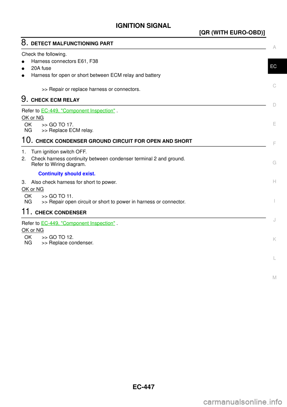
8. DETECT MALFUNCTIONING PART
Check the following.
�Harness connectors E61, F38
�20A fuse
�Harness for open or short between ECM relay and battery
>> Repair or replace harness or connectors.
9. CHECK ECM RELAY
Refer to EC-449, "
Component Inspection" .
OK or NG
OK >> GO TO 17.
NG >> Replace ECM relay.
10. CHECK CONDENSER GROUND CIRCUIT FOR OPEN AND SHORT
1. Turn ignition switch OFF.
2. Check harness continuity between condenser terminal 2 and ground.
Refer to Wiring diagram.
3. Also check harness for short to power.
OK or NG
OK >> GO TO 11.
NG >> Repair open circuit or short to power in harness or connector.
11 . CHECK CONDENSER
Refer to EC-449, "
Component Inspection" .
OK or NG
OK >> GO TO 12.
NG >> Replace condenser.Continuity should exist.
Page 859 of 4555
![NISSAN X-TRAIL 2005 Service Repair Manual INJECTOR CIRCUIT
EC-455
[QR (WITH EURO-OBD)]
C
D
E
F
G
H
I
J
K
L
MA
EC
3. CHECK INJECTOR POWER SUPPLY CIRCUIT
1. Turn ignition switch OFF.
2. Disconnect injector harness connector.
3. Turn ignition](/manual-img/5/57403/w960_57403-858.png "NISSAN X-TRAIL 2005 Service Repair Manual INJECTOR CIRCUIT
EC-455
[QR (WITH EURO-OBD)]
C
D
E
F
G
H
I
J
K
L
MA
EC
3. CHECK INJECTOR POWER SUPPLY CIRCUIT
1. Turn ignition switch OFF.
2. Disconnect injector harness connector.
3. Turn ignition")
INJECTOR CIRCUIT
EC-455
[QR (WITH EURO-OBD)]
C
D
E
F
G
H
I
J
K
L
MA
EC
3. CHECK INJECTOR POWER SUPPLY CIRCUIT
1. Turn ignition switch OFF.
2. Disconnect injector harness connector.
3. Turn ignition switch ON.
4. Check voltage between injector terminal 1 and ground with
CONSULT-II or tester.
OK or NG
OK >> GO TO 5.
NG >> GO TO 4.
4. DETECT MALFUNCTIONING PART
Check the following.
�Harness connectors M61, F41
�Harness connectors F1, F101
�Fuse block (J/B) connector M1
�10A fuse
�Harness for open or short between injector and fuse
>> Repair open circuit or short to ground or short to power in harness or connectors.
5. CHECK INJECTOR OUTPUT SIGNAL CIRCUIT FOR OPEN AND SHORT
1. Turn ignition switch OFF.
2. Disconnect ECM harness connector.
3. Check harness continuity between injector terminal 2 and ECM terminals 22, 23, 41, 42.
Refer to Wiring Diagram.
4. Also check harness for short to ground and short to power.
OK or NG
OK >> GO TO 7.
NG >> GO TO 6.
PBIB1970E
Voltage: Battery voltage
PBIB0582E
Continuity should exist.
![NISSAN X-TRAIL 2005 Service Repair Manual DTC P1217 ENGINE OVER TEMPERATURE
EC-363
[QR (WITH EURO-OBD)]
C
D
E
F
G
H
I
J
K
L
MA
EC
PROCEDURE A
1. CHECK COOLING FAN POWER SUPPLY CIRCUIT
1. Turn ignition switch OFF.
2. Disconnect cooling fan r](/manual-img/5/57403/w960_57403-766.png "NISSAN X-TRAIL 2005 Service Repair Manual DTC P1217 ENGINE OVER TEMPERATURE
EC-363
[QR (WITH EURO-OBD)]
C
D
E
F
G
H
I
J
K
L
MA
EC
PROCEDURE A
1. CHECK COOLING FAN POWER SUPPLY CIRCUIT
1. Turn ignition switch OFF.
2. Disconnect cooling fan r")