Page 4205 of 4555
WARNING CHIME
DI-57
C
D
E
F
G
H
I
J
L
MA
B
DI
Wiring Diagram — CHIME —/LHD ModelsEKS002XJ
TKWA1626E
Page 4206 of 4555
DI-58
WARNING CHIME
Wiring Diagram — CHIME —/RHD ModelsEKS00EKI
TKWA1628E
Page 4207 of 4555
WARNING CHIME
DI-59
C
D
E
F
G
H
I
J
L
MA
B
DI
TKWA1629E
Page 4208 of 4555

DI-60
WARNING CHIME
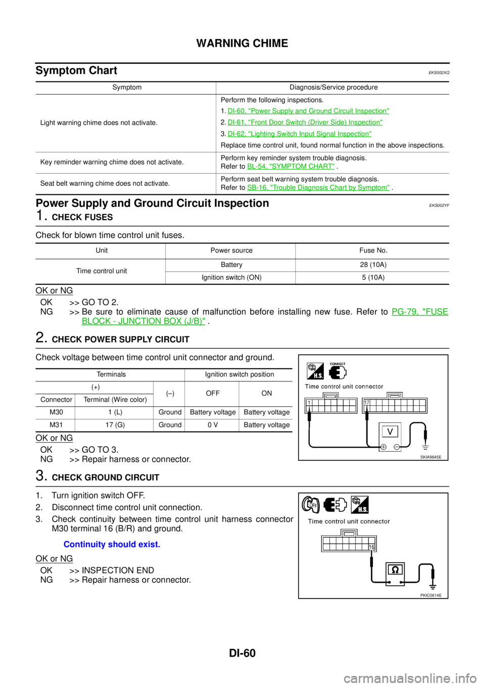
Symptom ChartEKS002XQ
Power Supply and Ground Circuit InspectionEKS002YF
1. CHECK FUSES
Check for blown time control unit fuses.
OK or NG
OK >> GO TO 2.
NG >> Be sure to eliminate cause of malfunction before installing new fuse. Refer to PG-79, "
FUSE
BLOCK - JUNCTION BOX (J/B)" .
2. CHECK POWER SUPPLY CIRCUIT
Check voltage between time control unit connector and ground.
OK or NG
OK >> GO TO 3.
NG >> Repair harness or connector.
3. CHECK GROUND CIRCUIT
1. Turn ignition switch OFF.
2. Disconnect time control unit connection.
3. Check continuity between time control unit harness connector
M30 terminal 16 (B/R) and ground.
OK or NG
OK >> INSPECTION END
NG >> Repair harness or connector.
Symptom Diagnosis/Service procedure
Light warning chime does not activate.Perform the following inspections.
1.DI-60, "
Power Supply and Ground Circuit Inspection"
2.DI-61, "Front Door Switch (Driver Side) Inspection"
3.DI-62, "Lighting Switch Input Signal Inspection"
Replace time control unit, found normal function in the above inspections.
Key reminder warning chime does not activate. Perform key reminder system trouble diagnosis.
Refer to BL-54, "
SYMPTOM CHART" .
Seat belt warning chime does not activate.Perform seat belt warning system trouble diagnosis.
Refer to SB-16, "
Trouble Diagnosis Chart by Symptom" .
Unit Power source Fuse No.
Time control unitBattery 28 (10A)
Ignition switch (ON) 5 (10A)
Terminals Ignition switch position
(+)
(–) OFF ON
Connector Terminal (Wire color)
M30 1 (L) Ground Battery voltage Battery voltage
M31 17 (G) Ground 0 V Battery voltage
SKIA9645E
Continuity should exist.
PKIC0614E
Page 4209 of 4555

WARNING CHIME
DI-61
C
D
E
F
G
H
I
J
L
MA
B
DI
Front Door Switch (Driver Side) InspectionEKS002YH
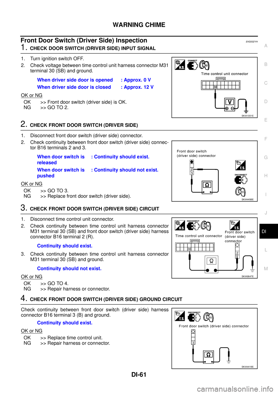
1. CHECK DOOR SWITCH (DRIVER SIDE) INPUT SIGNAL
1. Turn ignition switch OFF.
2. Check voltage between time control unit harness connector M31
terminal 30 (SB) and ground.
OK or NG
OK >> Front door switch (driver side) is OK.
NG >> GO TO 2.
2. CHECK FRONT DOOR SWITCH (DRIVER SIDE)
1. Disconnect front door switch (driver side) connector.
2. Check continuity between front door switch (driver side) connec-
tor B16 terminals 2 and 3.
OK or NG
OK >> GO TO 3.
NG >> Replace front door switch (driver side).
3. CHECK FRONT DOOR SWITCH (DRIVER SIDE) CIRCUIT
1. Disconnect time control unit connector.
2. Check continuity between time control unit harness connector
M31 terminal 30 (SB) and front door switch (driver side) harness
connector B16 terminal 2 (R).
3. Check continuity between time control unit harness connector
M31 terminal 30 (SB) and ground.
OK or NG
OK >> GO TO 4.
NG >> Repair harness or connector.
4. CHECK FRONT DOOR SWITCH (DRIVER SIDE) GROUND CIRCUIT
Check continuity between front door switch (driver side) harness
connector B16 terminal 3 (B) and ground.
OK or NG
OK >> Replace time control unit.
NG >> Repair harness or connector.When driver side door is opened : Approx. 0 V
When driver side door is closed : Approx. 12 V
SKIA1001E
When door switch is
released: Continuity should exist.
When door switch is
pushed: Continuity should not exist.
SKIA4498E
Continuity should exist.
Continuity should not exist.
SKIA9647E
Continuity should exist.
SKIA4418E
Page 4210 of 4555

DI-62
WARNING CHIME
Lighting Switch Input Signal Inspection EKS002XU
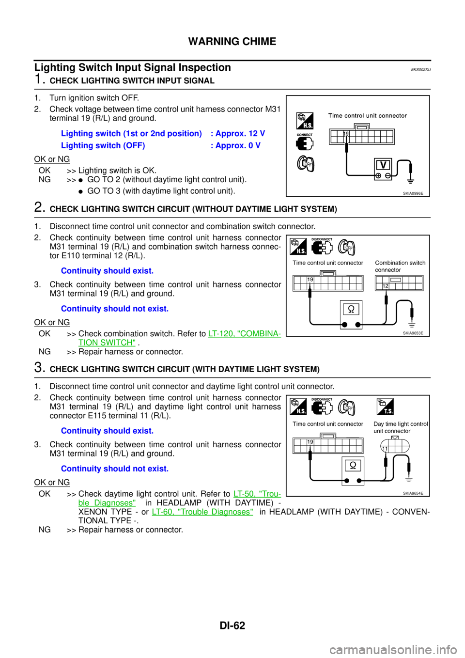
1. CHECK LIGHTING SWITCH INPUT SIGNAL
1. Turn ignition switch OFF.
2. Check voltage between time control unit harness connector M31
terminal 19 (R/L) and ground.
OK or NG
OK >> Lighting switch is OK.
NG >>
�GO TO 2 (without daytime light control unit).
�GO TO 3 (with daytime light control unit).
2. CHECK LIGHTING SWITCH CIRCUIT (WITHOUT DAYTIME LIGHT SYSTEM)
1. Disconnect time control unit connector and combination switch connector.
2. Check continuity between time control unit harness connector
M31 terminal 19 (R/L) and combination switch harness connec-
tor E110 terminal 12 (R/L).
3. Check continuity between time control unit harness connector
M31 terminal 19 (R/L) and ground.
OK or NG
OK >> Check combination switch. Refer to LT- 1 2 0 , "COMBINA-
TION SWITCH" .
NG >> Repair harness or connector.
3. CHECK LIGHTING SWITCH CIRCUIT (WITH DAYTIME LIGHT SYSTEM)
1. Disconnect time control unit connector and daytime light control unit connector.
2. Check continuity between time control unit harness connector
M31 terminal 19 (R/L) and daytime light control unit harness
connector E115 terminal 11 (R/L).
3. Check continuity between time control unit harness connector
M31 terminal 19 (R/L) and ground.
OK or NG
OK >> Check daytime light control unit. Refer to LT- 5 0 , "Trou-
ble Diagnoses" in HEADLAMP (WITH DAYTIME) -
XENON TYPE - or LT- 6 0 , "
Trouble Diagnoses" in HEADLAMP (WITH DAYTIME) - CONVEN-
TIONAL TYPE -.
NG >> Repair harness or connector.Lighting switch (1st or 2nd position) : Approx. 12 V
Lighting switch (OFF) : Approx. 0 V
SKIA0996E
Continuity should exist.
Continuity should not exist.
SKIA9653E
Continuity should exist.
Continuity should not exist.
SKIA9654E
Page 4215 of 4555

PRECAUTIONS
WW-3
C
D
E
F
G
H
I
J
L
MA
B
WW
PRECAUTIONS PFP:00011
Precautions for Supplemental Restraint System (SRS) “AIR BAG” and “SEAT
BELT PRE-TENSIONER”
EKS0079K
The Supplemental Restraint System such as “AIR BAG” and “SEAT BELT PRE-TENSIONER”, used along
with a front seat belt, helps to reduce the risk or severity of injury to the driver and front passenger for certain
types of collision. Information necessary to service the system safely is included in the SRS and SB section of
this Service Manual.
WARNING:
�To avoid rendering the SRS inoperative, which could increase the risk of personal injury or death
in the event of a collision which would result in air bag inflation, all maintenance must be per-
formed by an authorized NISSAN/INFINITI dealer.
�Improper maintenance, including incorrect removal and installation of the SRS, can lead to per-
sonal injury caused by unintentional activation of the system. For removal of Spiral Cable and Air
Bag Module, see the SRS section.
�Do not use electrical test equipment on any circuit related to the SRS unless instructed to in this
Service Manual. SRS wiring harnesses can be identified by yellow and/or orange harnesses or
harness connectors.
Wiring Diagrams and Trouble Diagnosis EKS0079L
When you read wiring diagrams, refer to the following:
�Refer to GI-14, "How to Read Wiring Diagrams" in GI section
�Refer to PG-2, "POWER SUPPLY ROUTING" for power distribution circuit in PG section
When you perform trouble diagnosis, refer to the following:
�Refer to GI-10, "HOW TO FOLLOW TEST GROUPS IN TROUBLE DIAGNOSES" in GI section
�Refer to GI-23, "How to Perform Efficient Diagnosis for an Electrical Incident" in GI section
Page 4247 of 4555
![NISSAN X-TRAIL 2005 Service Repair Manual PRECAUTIONS
LAN-3
[CAN]
C
D
E
F
G
H
I
J
L
MA
B
LAN
[CAN]PRECAUTIONSPFP:00001
Precautions for Supplemental Restraint System (SRS) “AIR BAG” and “SEAT
BELT PRE-TENSIONER”
EKS001U0
The Supplem NISSAN X-TRAIL 2005 Service Repair Manual PRECAUTIONS
LAN-3
[CAN]
C
D
E
F
G
H
I
J
L
MA
B
LAN
[CAN]PRECAUTIONSPFP:00001
Precautions for Supplemental Restraint System (SRS) “AIR BAG” and “SEAT
BELT PRE-TENSIONER”
EKS001U0
The Supplem](/manual-img/5/57403/w960_57403-4246.png)
PRECAUTIONS
LAN-3
[CAN]
C
D
E
F
G
H
I
J
L
MA
B
LAN
[CAN]PRECAUTIONSPFP:00001
Precautions for Supplemental Restraint System (SRS) “AIR BAG” and “SEAT
BELT PRE-TENSIONER”
EKS001U0
The Supplemental Restraint System such as “AIR BAG” and “SEAT BELT PRE-TENSIONER”, used along
with a front seat belt, helps to reduce the risk or severity of injury to the driver and front passenger for certain
types of collision. Information necessary to service the system safely is included in the SRS and SB section of
this Service Manual.
WARNING:
�To avoid rendering the SRS inoperative, which could increase the risk of personal injury or death
in the event of a collision which would result in air bag inflation, all maintenance must be per-
formed by an authorized NISSAN/INFINITI dealer.
�Improper maintenance, including incorrect removal and installation of the SRS, can lead to per-
sonal injury caused by unintentional activation of the system. For removal of Spiral Cable and Air
Bag Module, see the SRS section.
�Do not use electrical test equipment on any circuit related to the SRS unless instructed to in this
Service Manual. SRS wiring harnesses can be identified by yellow and/or orange harnesses or
harness connectors.
Precautions For Trouble DiagnosisEKS001U1
CAN SYSTEM
�Do not apply voltage of 7.0 V or higher to the measurement terminals.
�Use the tester with its open terminal voltage being 7.0 V or less.
�Be sure to turn ignition switch off and disconnect the battery cable from the negative terminal before
checking the circuit.
Precautions For Harness RepairEKS001U2
CAN SYSTEM
�Solder the repaired parts, and wrap with tape. [Frays of twisted
line must be within 110 mm (4.33 in).]
�Do not perform bypass wire connections for the repair parts.
(The spliced wire will become separated and the characteristics
of twisted line will be lost.)
PKIA0306E
PKIA0307E