2005 NISSAN X-TRAIL warning
[x] Cancel search: warningPage 3526 of 4555
SB-18
SEAT BELT WARNING SYSTEM
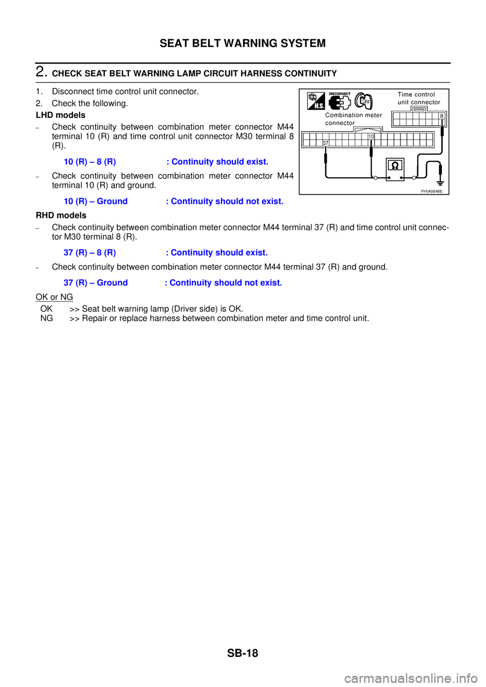
2. CHECK SEAT BELT WARNING LAMP CIRCUIT HARNESS CONTINUITY
1. Disconnect time control unit connector.
2. Check the following.
LHD models
–Check continuity between combination meter connector M44
terminal 10 (R) and time control unit connector M30 terminal 8
(R).
–Check continuity between combination meter connector M44
terminal 10 (R) and ground.
RHD models
–Check continuity between combination meter connector M44 terminal 37 (R) and time control unit connec-
tor M30 terminal 8 (R).
–Check continuity between combination meter connector M44 terminal 37 (R) and ground.
OK or NG
OK >> Seat belt warning lamp (Driver side) is OK.
NG >> Repair or replace harness between combination meter and time control unit.10 (R) – 8 (R) : Continuity should exist.
10 (R) – Ground : Continuity should not exist.
37 (R) – 8 (R) : Continuity should exist.
37 (R) – Ground : Continuity should not exist.
PHIA0648E
Page 3527 of 4555
SEAT BELT WARNING SYSTEM
SB-19
C
D
E
F
G
I
J
K
L
MA
B
SB
Seat belt Warning Lamp Check (Passenger Side)EHS000GU
1. CHECK SEAT BELT WARNING LAMP CIRCUIT
1. Turn ignition switch OFF.
2. Disconnect combination meter connector.
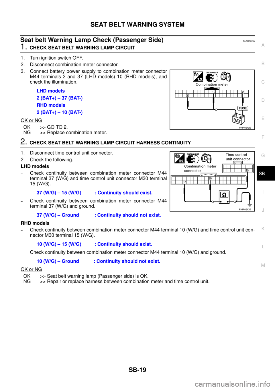
3. Connect battery power supply to combination meter connector
M44 terminals 2 and 37 (LHD models) 10 (RHD models), and
check the illumination.
OK or NG
OK >> GO TO 2.
NG >> Replace combination meter.
2. CHECK SEAT BELT WARNING LAMP CIRCUIT HARNESS CONTINUITY
1. Disconnect time control unit connector.
2. Check the following.
LHD models
–Check continuity between combination meter connector M44
terminal 37 (W/G) and time control unit connector M30 terminal
15 (W/G).
–Check continuity between combination meter connector M44
terminal 37 (W/G) and ground.
RHD models
–Check continuity between combination meter connector M44 terminal 10 (W/G) and time control unit con-
nector M30 terminal 15 (W/G).
–Check continuity between combination meter connector M44 terminal 10 (W/G) and ground.
OK or NG
OK >> Seat belt warning lamp (Passenger side) is OK.
NG >> Repair or replace harness between combination meter and time control unit.LHD models
2 (BAT+) – 37 (BAT-)
RHD models
2 (BAT+) – 10 (BAT-)
PHIA0642E
37 (W/G) – 15 (W/G) : Continuity should exist.
37 (W/G) – Ground : Continuity should not exist.
10 (W/G) – 15 (W/G) : Continuity should exist.
10 (W/G) – Ground : Continuity should not exist.
PHIA0643E
Page 3528 of 4555
SB-20
SEAT BELT WARNING SYSTEM
Seat Belt Buckle Switch CheckEHS000GW
1. CHECK SEAT BELT BUCKLE SWITCH (DRIVER SIDE) INPUT SIGNAL
1. Turn ignition switch “ON”.
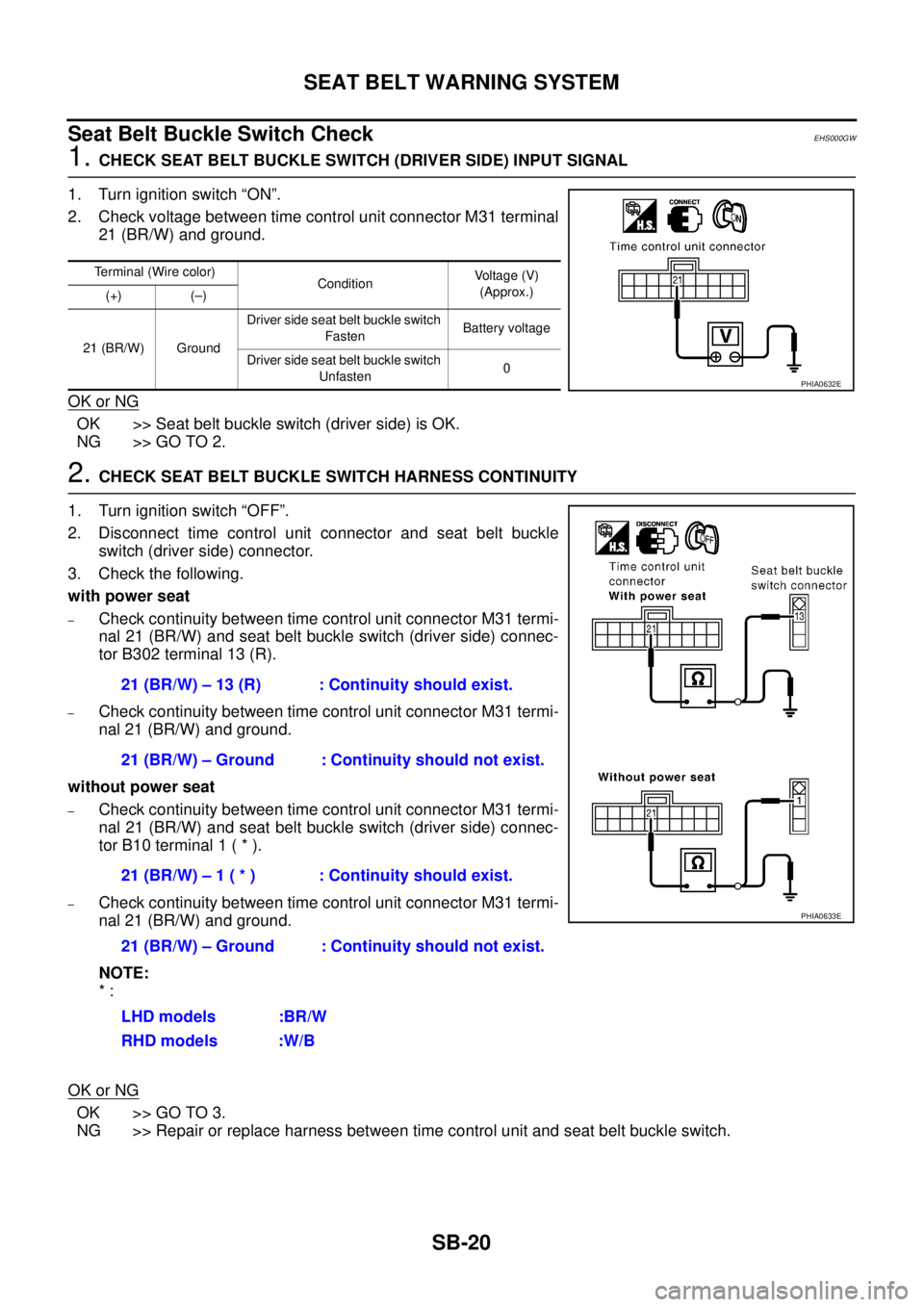
2. Check voltage between time control unit connector M31 terminal
21 (BR/W) and ground.
OK or NG
OK >> Seat belt buckle switch (driver side) is OK.
NG >> GO TO 2.
2. CHECK SEAT BELT BUCKLE SWITCH HARNESS CONTINUITY
1. Turn ignition switch “OFF”.
2. Disconnect time control unit connector and seat belt buckle
switch (driver side) connector.
3. Check the following.
with power seat
–Check continuity between time control unit connector M31 termi-
nal 21 (BR/W) and seat belt buckle switch (driver side) connec-
tor B302 terminal 13 (R).
–Check continuity between time control unit connector M31 termi-
nal 21 (BR/W) and ground.
without power seat
–Check continuity between time control unit connector M31 termi-
nal 21 (BR/W) and seat belt buckle switch (driver side) connec-
tor B10 terminal 1 ( * ).
–Check continuity between time control unit connector M31 termi-
nal 21 (BR/W) and ground.
NOTE:
* :
OK or NG
OK >> GO TO 3.
NG >> Repair or replace harness between time control unit and seat belt buckle switch.
Terminal (Wire color)
ConditionVoltage (V)
(Approx.)
(+) (–)
21 (BR/W) GroundDriver side seat belt buckle switch
FastenBattery voltage
Driver side seat belt buckle switch
Unfasten0
PHIA0632E
21 (BR/W) – 13 (R) : Continuity should exist.
21 (BR/W) – Ground : Continuity should not exist.
21 (BR/W) – 1 ( * ) : Continuity should exist.
21 (BR/W) – Ground : Continuity should not exist.
LHD models :BR/W
RHD models :W/B
PHIA0633E
Page 3529 of 4555
SEAT BELT WARNING SYSTEM
SB-21
C
D
E
F
G
I
J
K
L
MA
B
SB
3. CHECK SEAT BELT BUCKLE SWITCH (DRIVER SIDE)
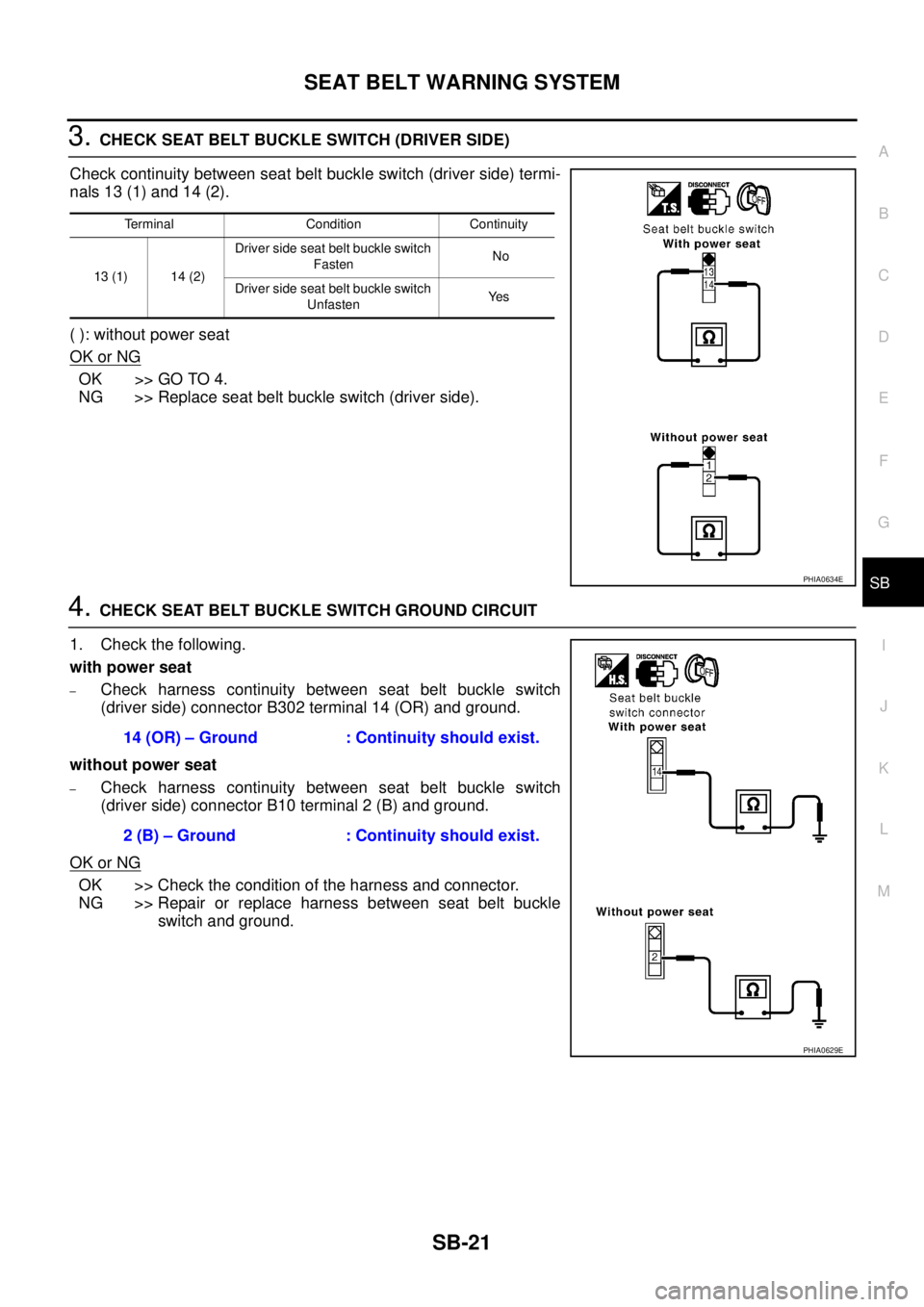
Check continuity between seat belt buckle switch (driver side) termi-
nals 13 (1) and 14 (2).
( ): without power seat
OK or NG
OK >> GO TO 4.
NG >> Replace seat belt buckle switch (driver side).
4. CHECK SEAT BELT BUCKLE SWITCH GROUND CIRCUIT
1. Check the following.
with power seat
–Check harness continuity between seat belt buckle switch
(driver side) connector B302 terminal 14 (OR) and ground.
without power seat
–Check harness continuity between seat belt buckle switch
(driver side) connector B10 terminal 2 (B) and ground.
OK or NG
OK >> Check the condition of the harness and connector.
NG >> Repair or replace harness between seat belt buckle
switch and ground.
Terminal Condition Continuity
13 (1) 14 (2)Driver side seat belt buckle switch
Fasten No
Driver side seat belt buckle switch
UnfastenYe s
PHIA0634E
14 (OR) – Ground : Continuity should exist.
2 (B) – Ground : Continuity should exist.
PHIA0629E
Page 3530 of 4555
SB-22
SEAT BELT WARNING SYSTEM
Seat Belt Buckle Switch and Seat Pressure Switch CheckEHS000GX
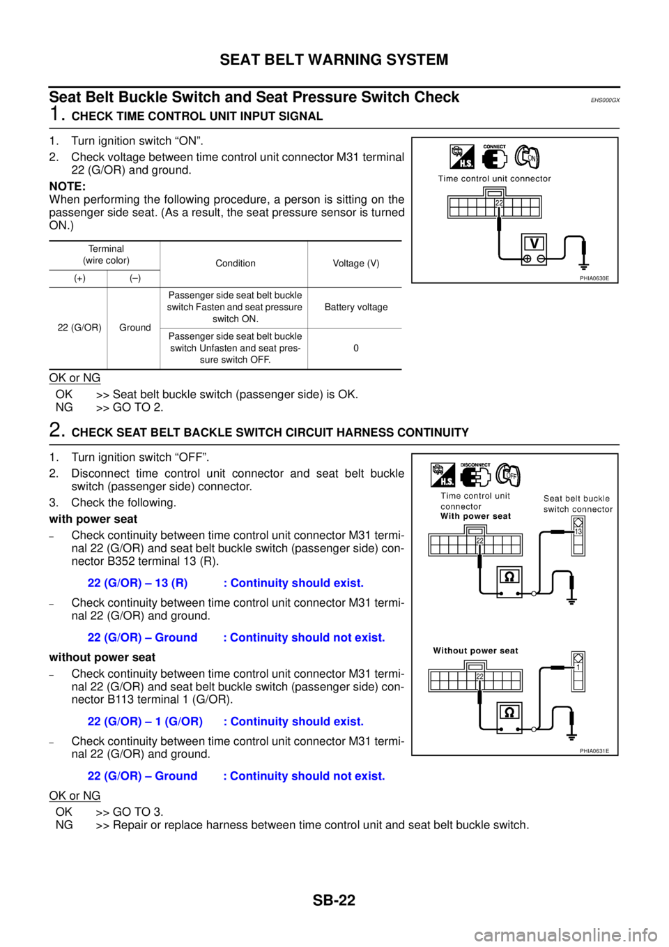
1. CHECK TIME CONTROL UNIT INPUT SIGNAL
1. Turn ignition switch “ON”.
2. Check voltage between time control unit connector M31 terminal
22 (G/OR) and ground.
NOTE:
When performing the following procedure, a person is sitting on the
passenger side seat. (As a result, the seat pressure sensor is turned
ON.)
OK or NG
OK >> Seat belt buckle switch (passenger side) is OK.
NG >> GO TO 2.
2. CHECK SEAT BELT BACKLE SWITCH CIRCUIT HARNESS CONTINUITY
1. Turn ignition switch “OFF”.
2. Disconnect time control unit connector and seat belt buckle
switch (passenger side) connector.
3. Check the following.
with power seat
–Check continuity between time control unit connector M31 termi-
nal 22 (G/OR) and seat belt buckle switch (passenger side) con-
nector B352 terminal 13 (R).
–Check continuity between time control unit connector M31 termi-
nal 22 (G/OR) and ground.
without power seat
–Check continuity between time control unit connector M31 termi-
nal 22 (G/OR) and seat belt buckle switch (passenger side) con-
nector B113 terminal 1 (G/OR).
–Check continuity between time control unit connector M31 termi-
nal 22 (G/OR) and ground.
OK or NG
OK >> GO TO 3.
NG >> Repair or replace harness between time control unit and seat belt buckle switch.
Terminal
(wire color)
Condition Voltage (V)
(+) (–)
22 (G/OR) GroundPassenger side seat belt buckle
switch Fasten and seat pressure
switch ON.Battery voltage
Passenger side seat belt buckle
switch Unfasten and seat pres-
sure switch OFF.0
PHIA0630E
22 (G/OR) – 13 (R) : Continuity should exist.
22 (G/OR) – Ground : Continuity should not exist.
22 (G/OR) – 1 (G/OR) : Continuity should exist.
22 (G/OR) – Ground : Continuity should not exist.
PHIA0631E
Page 3531 of 4555
SEAT BELT WARNING SYSTEM
SB-23
C
D
E
F
G
I
J
K
L
MA
B
SB
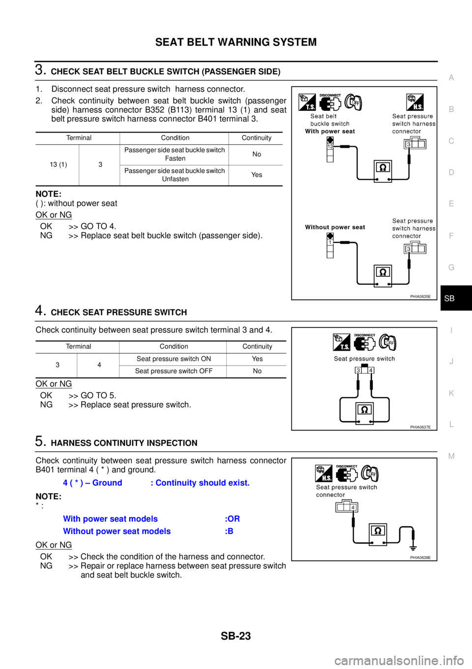
3. CHECK SEAT BELT BUCKLE SWITCH (PASSENGER SIDE)
1. Disconnect seat pressure switch harness connector.
2. Check continuity between seat belt buckle switch (passenger
side) harness connector B352 (B113) terminal 13 (1) and seat
belt pressure switch harness connector B401 terminal 3.
NOTE:
( ): without power seat
OK or NG
OK >> GO TO 4.
NG >> Replace seat belt buckle switch (passenger side).
4. CHECK SEAT PRESSURE SWITCH
Check continuity between seat pressure switch terminal 3 and 4.
OK or NG
OK >> GO TO 5.
NG >> Replace seat pressure switch.
5. HARNESS CONTINUITY INSPECTION
Check continuity between seat pressure switch harness connector
B401 terminal 4 ( * ) and ground.
NOTE:
* :
OK or NG
OK >> Check the condition of the harness and connector.
NG >> Repair or replace harness between seat pressure switch
and seat belt buckle switch.
Terminal Condition Continuity
13 (1) 3Passenger side seat buckle switch
FastenNo
Passenger side seat buckle switch
UnfastenYe s
PHIA0635E
Terminal Condition Continuity
34Seat pressure switch ON Yes
Seat pressure switch OFF No
PHIA0637E
4 ( * ) – Ground : Continuity should exist.
With power seat models :OR
Without power seat models :B
PHIA0638E
Page 3532 of 4555
SB-24
SEAT BELT WARNING SYSTEM
Vehicle Speed Signal InspectionEHS000GZ
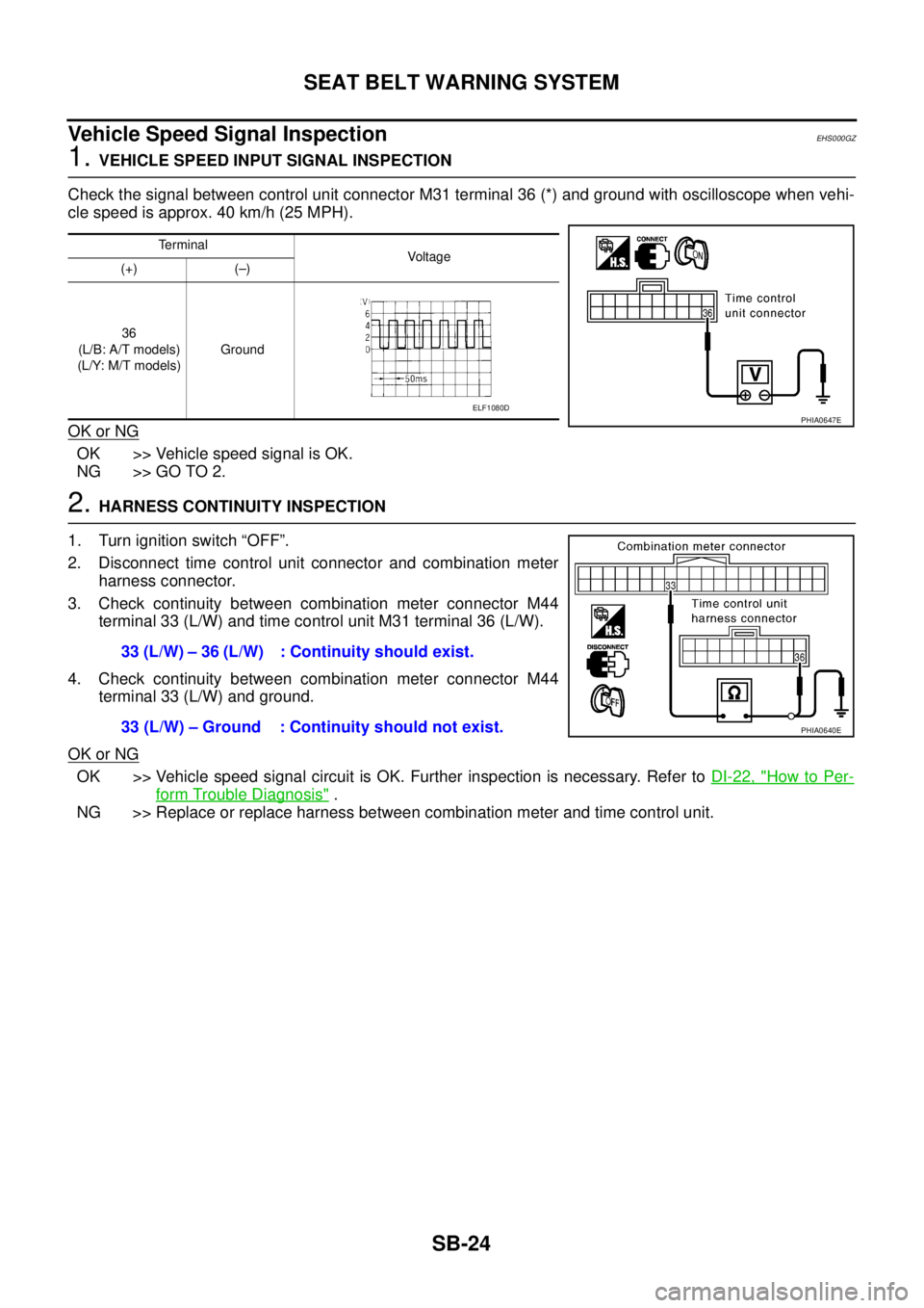
1. VEHICLE SPEED INPUT SIGNAL INSPECTION
Check the signal between control unit connector M31 terminal 36 (*) and ground with oscilloscope when vehi-
cle speed is approx. 40 km/h (25 MPH).
OK or NG
OK >> Vehicle speed signal is OK.
NG >> GO TO 2.
2. HARNESS CONTINUITY INSPECTION
1. Turn ignition switch “OFF”.
2. Disconnect time control unit connector and combination meter
harness connector.
3. Check continuity between combination meter connector M44
terminal 33 (L/W) and time control unit M31 terminal 36 (L/W).
4. Check continuity between combination meter connector M44
terminal 33 (L/W) and ground.
OK or NG
OK >> Vehicle speed signal circuit is OK. Further inspection is necessary. Refer to DI-22, "How to Per-
form Trouble Diagnosis" .
NG >> Replace or replace harness between combination meter and time control unit.
Terminal
Voltag e
(+) (–)
36
(L/B: A/T models)
(L/Y: M/T models)Ground
PHIA0647EELF1080D
33 (L/W) – 36 (L/W) : Continuity should exist.
33 (L/W) – Ground : Continuity should not exist.
PHIA0640E
Page 3533 of 4555

SRS-1
SUPPLEMENTAL RESTRAINT SYSTEM (SRS)
H RESTRAINTS
CONTENTS
C
D
E
F
G
I
J
K
L
M
SECTION SRS
A
B
SRS
SUPPLEMENTAL RESTRAINT SYSTEM (SRS)
PRECAUTIONS .......................................................... 3
Precautions for Supplemental Restraint System
(SRS) “AIR BAG” and “SEAT BELT PRE-TEN-
SIONER” .................................................................. 3
Precautions for SRS “AIR BAG” and “SEAT BELT
PRE-TENSIONER” Service ..................................... 3
Wiring Diagrams and Trouble Diagnosis .................. 3
PREPARATION ........................................................... 4
Special Service Tools ............................................... 4
Commercial Service Tools ........................................ 5
SUPPLEMENTAL RESTRAINT SYSTEM (SRS) ....... 6
SRS Configuration ................................................... 6
Front Seat Belt Pre-tensioner with Load Limiter ...... 6
Front Side Air Bag .................................................... 7
TROUBLE DIAGNOSIS .............................................. 8
Trouble Diagnosis Introduction ................................. 8
DIAGNOSIS FUNCTION ....................................... 8
HOW TO PERFORM TROUBLE DIAGNOSES
FOR QUICK AND ACCURATE REPAIR ............... 8
WORK FLOW ........................................................ 9
Component Parts Location ..................................... 10
Wiring Diagram — SRS — /LHD models ................ 11
Wiring Diagram — SRS — /RHD models .............. 13
CONSULT-II Function ............................................ 15
DIAGNOSIS MODE FOR CONSULT-II ............... 15
HOW TO CHANGE SELF-DIAGNOSIS MODE
WITH CONSULT-II .............................................. 15
HOW TO ERASE SELF-DIAGNOSIS RESULTS ... 16
Self-Diagnosis Function (Without CONSULT-II) ..... 16
HOW TO CHANGE SELF-DIAGNOSIS MODE
WITHOUT CONSULT-II ...................................... 16
HOW TO ERASE SELF-DIAGNOSIS RESULTS ... 16
SRS Operation Check ............................................ 17
DIAGNOSTIC PROCEDURE 1 ........................... 17
Trouble Diagnosis with CONSULT–II ..................... 19
DIAGNOSTIC PROCEDURE 2 ........................... 19
DIAGNOSTIC PROCEDURE 3 ........................... 21
Diagnostic Code Chart ........................................... 22
Trouble Diagnosis without CONSULT-II ................. 24
DIAGNOSTIC PROCEDURE 4 ........................... 24WARNING LAMP FLASH CODE CHART ........... 25
Trouble Diagnosis: “AIR BAG” Warning Lamp Does
Not Turn OFF ......................................................... 28
DIAGNOSTIC PROCEDURE 5 ........................... 28
Trouble Diagnosis: “AIR BAG” Warning Lamp Does
Not Turn ON ........................................................... 29
DIAGNOSTIC PROCEDURE 6 ........................... 29
DRIVER AIR BAG MODULE .................................... 30
Removal and Installation ........................................ 30
REMOVAL ........................................................... 30
INSTALLATION ................................................... 31
SPIRAL CABLE ........................................................ 33
Removal and Installation ........................................ 33
REMOVAL ........................................................... 33
INSTALLATION ................................................... 34
FRONT PASSENGER AIR BAG MODULE .............. 35
Removal and Installation ........................................ 35
REMOVAL ........................................................... 35
INSTALLATION ................................................... 36
FRONT SIDE AIR BAG MODULE ............................ 37
Removal and Installation ........................................ 37
REMOVAL ........................................................... 37
INSTALLATION ................................................... 38
SIDE AIR BAG (SATELLITE) SENSOR ................... 39
Removal and Installation ........................................ 39
REMOVAL ........................................................... 39
INSTALLATION ................................................... 39
FRONT SEAT BELT PRE-TENSIONER ................... 40
Removal and Installation ........................................ 40
DIAGNOSIS SENSOR UNIT ..................................... 41
Removal and Installation ........................................ 41
REMOVAL ........................................................... 41
INSTALLATION ................................................... 41
ECU DISCRIMINATED NO. ................................ 41
DISPOSAL OF AIR BAG MODULE AND SEAT BELT
PRE-TENSIONER ..................................................... 42
Caution for Air Bag Module and Seat Belt Pre-ten-
sioner ...................................................................... 42
CHECKING DEPLOYMENT TOOL ..................... 42
DEPLOYMENT PROCEDURES FOR AIR BAG