Page 3045 of 4555
PARKING BRAKE SHOE
PB-7
C
D
E
G
H
I
J
K
L
MA
B
PB
2. Attach upper-side return springs to brake shoe as shown in the
figure. Be sure to install return spring B over return spring A.
3. Orientation of adjusters is different for LH adjuster and RH
adjuster. Assemble adjusters so that threaded part is expanded
when rotating it to direction shown by arrow. Contract adjuster to
assemble.
CAUTION:
When adjuster was disassembled, apply brake grease to thread.
4. Assemble torque lever in direction of installation as shown in the
figure.
SFIA0281E
SFIA2426E
SBR096C
Page 3173 of 4555
EXHAUST SYSTEM
EX-3
C
D
E
F
G
H
I
J
K
L
MA
EX
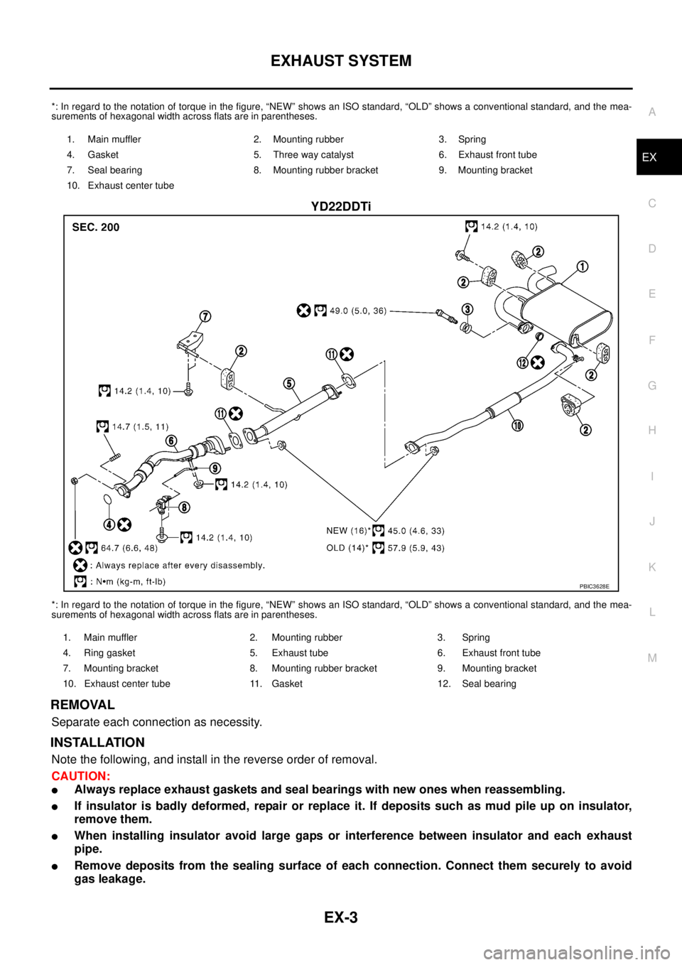
*: In regard to the notation of torque in the figure, “NEW” shows an ISO standard, “OLD” shows a conventional standard, and the mea-
surements of hexagonal width across flats are in parentheses.
YD22DDTi
*: In regard to the notation of torque in the figure, “NEW” shows an ISO standard, “OLD” shows a conventional standard, and the mea-
surements of hexagonal width across flats are in parentheses.
REMOVAL
Separate each connection as necessity.
INSTALLATION
Note the following, and install in the reverse order of removal.
CAUTION:
�Always replace exhaust gaskets and seal bearings with new ones when reassembling.
�If insulator is badly deformed, repair or replace it. If deposits such as mud pile up on insulator,
remove them.
�When installing insulator avoid large gaps or interference between insulator and each exhaust
pipe.
�Remove deposits from the sealing surface of each connection. Connect them securely to avoid
gas leakage.
1. Main muffler 2. Mounting rubber 3. Spring
4. Gasket 5. Three way catalyst 6. Exhaust front tube
7. Seal bearing 8. Mounting rubber bracket 9. Mounting bracket
10. Exhaust center tube
PBIC3628E
1. Main muffler 2. Mounting rubber 3. Spring
4. Ring gasket 5. Exhaust tube 6. Exhaust front tube
7. Mounting bracket 8. Mounting rubber bracket 9. Mounting bracket
10. Exhaust center tube 11. Gasket 12. Seal bearing
Page 3174 of 4555
EX-4
EXHAUST SYSTEM
�Temporarily tighten mounting nuts on the exhaust manifold side and mounting bolts on the vehi-
cle side. Check each part for unusual interference, and then tighten them to the specified torque.
�When installing each mounting rubber, avoid twisting or unusual extension in up/down and right/
left directions.
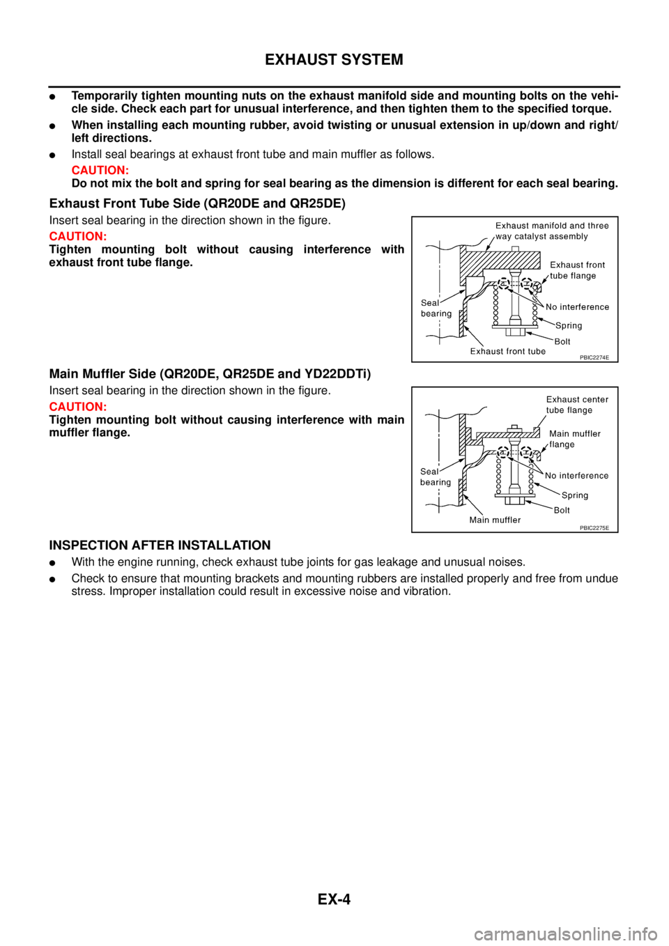
�Install seal bearings at exhaust front tube and main muffler as follows.
CAUTION:
Do not mix the bolt and spring for seal bearing as the dimension is different for each seal bearing.
Exhaust Front Tube Side (QR20DE and QR25DE)
Insert seal bearing in the direction shown in the figure.
CAUTION:
Tighten mounting bolt without causing interference with
exhaust front tube flange.
Main Muffler Side (QR20DE, QR25DE and YD22DDTi)
Insert seal bearing in the direction shown in the figure.
CAUTION:
Tighten mounting bolt without causing interference with main
muffler flange.
INSPECTION AFTER INSTALLATION
�With the engine running, check exhaust tube joints for gas leakage and unusual noises.
�Check to ensure that mounting brackets and mounting rubbers are installed properly and free from undue
stress. Improper installation could result in excessive noise and vibration.
PBIC2274E
PBIC2275E
Page 3470 of 4555
PS-8
STEERING WHEEL
STEERING WHEELPFP:48430
On-Vehicle Inspection and ServiceEGS001BY
CHECKING CONDITION OF INSTALLATION
�Check installation conditions of steering gear assembly, front suspension, axle and steering column.
�Check if movement exists when steering wheel is moved up and down, to the left and right and to the axial
direction.
�Check steering gear assembly mounting bolts and nut for looseness. Refer to PS-16, "COMPONENT" .
CHECKING STEERING WHEEL PLAY
�Turn steering wheel so that front wheels come to the straight-ahead position. Start engine and lightly turn
steering wheel to the left and right until front wheels start to move. Measure steering wheel movement on
the outer circumference.
�When the measurement value is outside the standard value, check backlash for each joint of steering col-
umn and installation condition of steering gear assembly.
CHECKING NEUTRAL POSITION STEERING WHEEL
�Make sure that steering gear assembly, steering column and steering wheel are installed in the correct
position.
�Perform neutral position inspection after wheel alignment. Refer to FSU-6, "Wheel Alignment" .
�Set vehicle to the straight-ahead position and confirm steering wheel is in the neutral position.
�Loosen outer socket lock nut and turn inner socket to left and right equally to make fine adjustments if
steering wheel is not in the neutral position.
CHECKING STEERING WHEEL TURNING FORCE
1. Park vehicle on a level and dry surface, set parking brake.
2. Start engine.
3. Bring power steering fluid up to adequate operating temperature. [Make sure temperature of fluid is
approximately 50 to 80°C (122 to 176°F).]
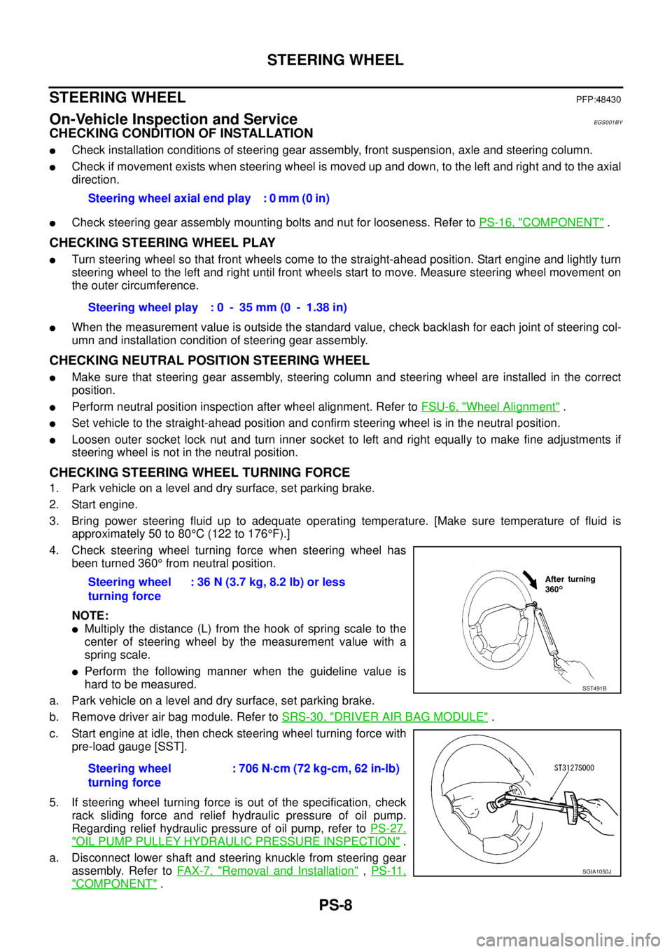
4. Check steering wheel turning force when steering wheel has
been turned 360° from neutral position.
NOTE:
�Multiply the distance (L) from the hook of spring scale to the
center of steering wheel by the measurement value with a
spring scale.
�Perform the following manner when the guideline value is
hard to be measured.
a. Park vehicle on a level and dry surface, set parking brake.
b. Remove driver air bag module. Refer to SRS-30, "
DRIVER AIR BAG MODULE" .
c. Start engine at idle, then check steering wheel turning force with
pre-load gauge [SST].
5. If steering wheel turning force is out of the specification, check
rack sliding force and relief hydraulic pressure of oil pump.
Regarding relief hydraulic pressure of oil pump, refer to PS-27,
"OIL PUMP PULLEY HYDRAULIC PRESSURE INSPECTION" .
a. Disconnect lower shaft and steering knuckle from steering gear
assembly. Refer to FAX-7, "
Removal and Installation" , PS-11,
"COMPONENT" . Steering wheel axial end play : 0 mm (0 in)
Steering wheel play : 0 - 35 mm (0 - 1.38 in)
Steering wheel
turning force: 36 N (3.7 kg, 8.2 lb) or less
Steering wheel
turning force: 706 N·cm (72 kg-cm, 62 in-lb)
SST491B
SGIA1050J
Page 3483 of 4555
POWER STEERING GEAR AND LINKAGE
PS-21
C
D
E
F
H
I
J
K
L
MA
B
PS
Gear Housing Assembly
Check gear housing assembly for damage and scratches (inner wall). Replace if there are.
Outer Socket and Inner Socket
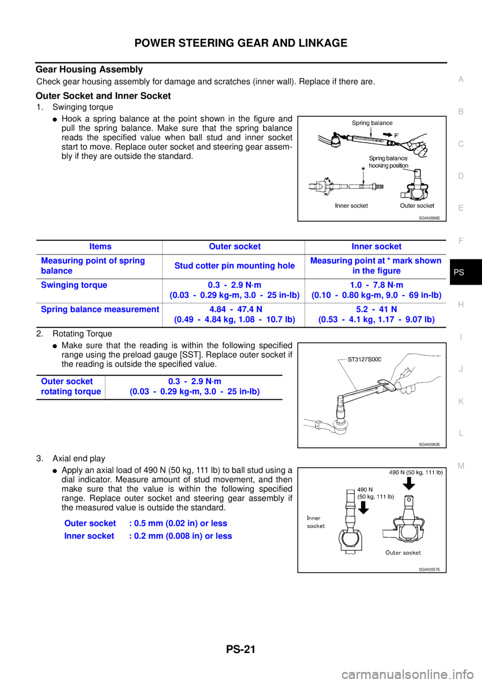
1. Swinging torque
�Hook a spring balance at the point shown in the figure and
pull the spring balance. Make sure that the spring balance
reads the specified value when ball stud and inner socket
start to move. Replace outer socket and steering gear assem-
bly if they are outside the standard.
2. Rotating Torque
�Make sure that the reading is within the following specified
range using the preload gauge [SST]. Replace outer socket if
the reading is outside the specified value.
3. Axial end play
�Apply an axial load of 490 N (50 kg, 111 lb) to ball stud using a
dial indicator. Measure amount of stud movement, and then
make sure that the value is within the following specified
range. Replace outer socket and steering gear assembly if
the measured value is outside the standard.
SGIA0896E
Items Outer socket Inner socket
Measuring point of spring
balanceStud cotter pin mounting holeMeasuring point at * mark shown
in the figure
Swinging torque 0.3 - 2.9 N·m
(0.03 - 0.29 kg-m, 3.0 - 25 in-lb)1.0 - 7.8 N·m
(0.10 - 0.80 kg-m, 9.0 - 69 in-lb)
Spring balance measurement 4.84 - 47.4 N
(0.49 - 4.84 kg, 1.08 - 10.7 lb)5.2 - 41 N
(0.53 - 4.1 kg, 1.17 - 9.07 lb)
Outer socket
rotating torque0.3 - 2.9 N·m
(0.03 - 0.29 kg-m, 3.0 - 25 in-lb)
SGIA0083E
Outer socket : 0.5 mm (0.02 in) or less
Inner socket : 0.2 mm (0.008 in) or less
SGIA0057E
Page 3490 of 4555
PS-28
POWER STEERING OIL PUMP
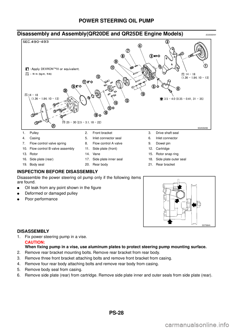
Disassembly and Assembly(QR20DE and QR25DE Engine Models)EGS000AH
INSPECTION BEFORE DISASSEMBLY
Disassemble the power steering oil pump only if the following items
are found.
�Oil leak from any point shown in the figure
�Deformed or damaged pulley
�Poor performance
DISASSEMBLY
1. Fix power steering pump in a vise.
CAUTION:
When fixing pump in a vise, use aluminum plates to protect steering pump mounting surface.
2. Remove rear bracket mounting bolts. Remove rear bracket from rear body.
3. Remove three front bracket attaching bolts and remove front bracket from casing.
4. Remove four rear body attaching bolts and remove rear body from casing.
5. Remove body seal from casing.
6. Remove side plate (rear) from cartridge. Remove side plate inner and outer seals from side plate (rear).
1. Pulley 2. Front bracket 3. Drive shaft seal
4. Casing 5. Inlet connector seal 6. Inlet connector
7. Flow control valve spring 8. Flow control A valve 9. Dowel pin
10. Flow control B valve assembly 11. Side plate (front) 12. Cartridge
13. Rotor 14. Vane 15. Rotor snap ring
16. Side plate (rear) 17. Side plate inner seal 18. Side plate outer seal
19. Body seal 20. Rear body 21. Rear bracket
SGIA0645E
SST984A
Page 3491 of 4555
POWER STEERING OIL PUMP
PS-29
C
D
E
F
H
I
J
K
L
MA
B
PS
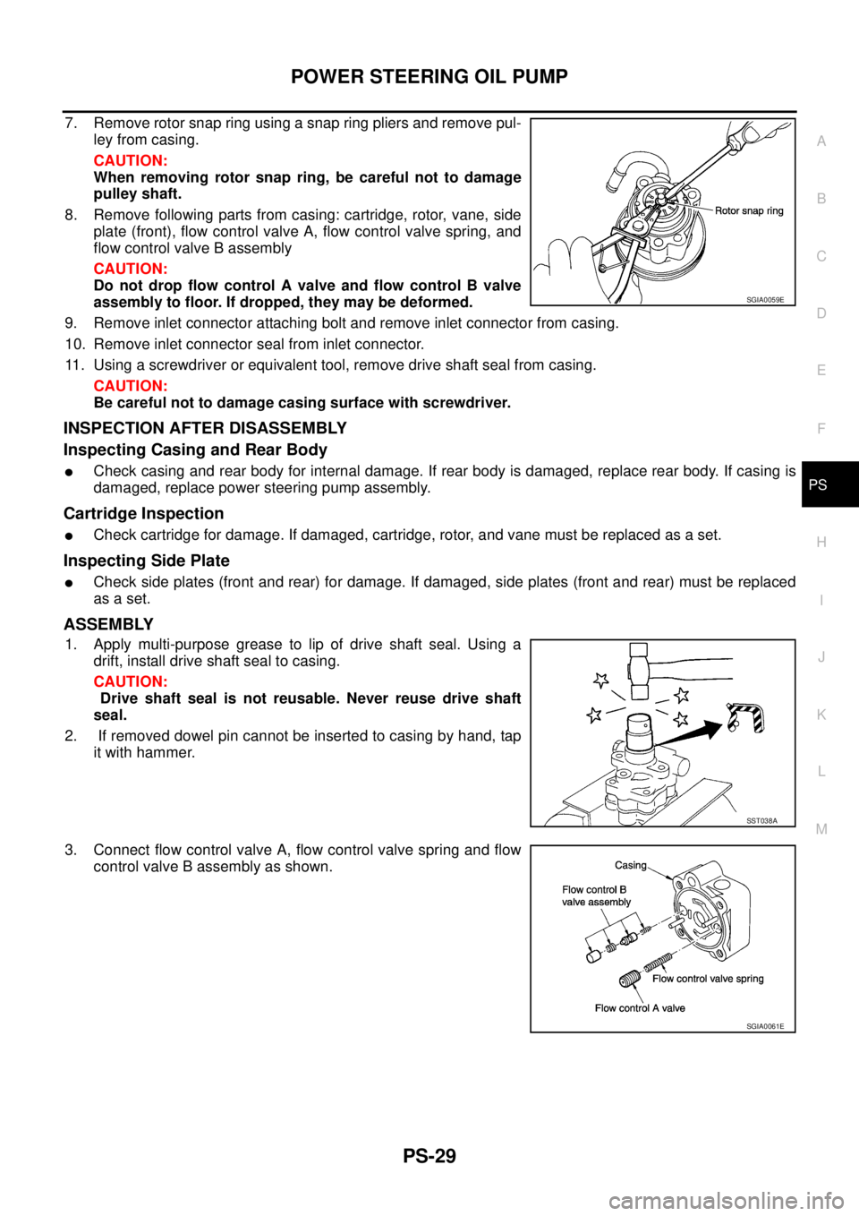
7. Remove rotor snap ring using a snap ring pliers and remove pul-
ley from casing.
CAUTION:
When removing rotor snap ring, be careful not to damage
pulley shaft.
8. Remove following parts from casing: cartridge, rotor, vane, side
plate (front), flow control valve A, flow control valve spring, and
flow control valve B assembly
CAUTION:
Do not drop flow control A valve and flow control B valve
assembly to floor. If dropped, they may be deformed.
9. Remove inlet connector attaching bolt and remove inlet connector from casing.
10. Remove inlet connector seal from inlet connector.
11. Using a screwdriver or equivalent tool, remove drive shaft seal from casing.
CAUTION:
Be careful not to damage casing surface with screwdriver.
INSPECTION AFTER DISASSEMBLY
Inspecting Casing and Rear Body
�Check casing and rear body for internal damage. If rear body is damaged, replace rear body. If casing is
damaged, replace power steering pump assembly.
Cartridge Inspection
�Check cartridge for damage. If damaged, cartridge, rotor, and vane must be replaced as a set.
Inspecting Side Plate
�Check side plates (front and rear) for damage. If damaged, side plates (front and rear) must be replaced
as a set.
ASSEMBLY
1. Apply multi-purpose grease to lip of drive shaft seal. Using a
drift, install drive shaft seal to casing.
CAUTION:
Drive shaft seal is not reusable. Never reuse drive shaft
seal.
2. If removed dowel pin cannot be inserted to casing by hand, tap
it with hammer.
3. Connect flow control valve A, flow control valve spring and flow
control valve B assembly as shown.
SGIA0059E
SST038A
SGIA0061E
Page 3495 of 4555
POWER STEERING OIL PUMP
PS-33
C
D
E
F
H
I
J
K
L
MA
B
PS
Disassembly and Assembly (YD22DDTi Engine Model)EGS000AJ
INSPECTION BEFORE DISASSEMBLY
Disassemble power steering oil pump only when any of following
cases meets.
�If oil leak is found on oil pump.
�Oil pump pulley is deformed or damaged.
�Performance of oil pump is low.
1. Rear bracket 2. Rear body 3. Dowel pin
4. Side plate seal 5. Cam ring 6. Vane
7. Rotor 8. Side plate 9. O-ring (Outer)
10. O-ring (Inner) 11. Front body 12. Drive shaft rear oil sear
13. Drive shaft front oil seal 14. Drive shaft 15. Snap ring
16. O-ring 17. Outlet connector 18. Connector seal
19. Flow control valve 20. Flow control valve spring 21. Inlet connector
22. O-ring 23. Copper washer
SGIA0646E
SST883C