Page 2984 of 4555
 to check abnormal free play.")
RSU-6
REAR SUSPENSION ASSEMBLY
On-Vehicle Inspection and ServiceEES0007F
Check axle and suspension parts for excessive play, wear, and damage.
�Move rear wheels (RH/LH) to check abnormal free play.
�Retighten all nuts and bolts to the specified torque.
�Check strut for oil leakage and damage.
Wheel AlignmentEES0007G
DESCRIPTION
�Measure wheel alignment under unladen conditions. “Unladen conditions” means that fuel, coolant, and
lubricant are full. However, spare tyre, jack, and hand tools should be unloaded.
PRELIMINARY INSPECTION
1. Check the tyre for improper air pressure and wear.
2. Check road wheels for runout.
3. Check wheel bearing axial endplay.
4. Check strut operation.
5. Check each mounting point of axle and suspension for looseness and deformation.
6. Check each link and arm for cracks, deformation, and other damage.
7. Check the vehicle posture.
CAMBER
Camber is preset at factory and cannot be adjusted.
�If the camber is not within specification, inspect and replace any damaged or worn rear suspension parts.
TOE-IN
Measure toe-in using the following procedure.
�Always perform following procedure on a flat surface.
�Make sure that no person is in front of the vehicle before push-
ing it.
1. Bounce rear of vehicle up and down to stabilize the posture.
2. Push the vehicle straight ahead about 5 m (16 ft).
3. Put a mark on base line of tread (rear side) of both tyre at the
same height as hub center. This mark is a measuring points.
1. Strut spacer 2. Strut mounting insulator 3. Strut mounting insulator bracket
4. Upper rubber seat 5. Bound bumper 6. Coil spring
7. Strut 8. Rear axle assembly 9. Rear suspension member
10. Member stopper 11. member stopper 12. Washer
13. Rear parallel link 14. Toe-in adjusting bolt 15. Front parallel link
16. Radius rod 17. Stabilizer bar 18. Clamp
19. Bushing 20. Connecting rod
Camber : RSU-14, "SERVICE DATA AND SPECIFICATIONS (SDS)"
AFA050
Page 2986 of 4555

RSU-8
COIL SPRING AND STRUT
COIL SPRING AND STRUTPFP:55302
Removal and InstallationEES0007H
REMOVAL
1. Remove tyre.
2. Remove brake hose lock plate and remove brake hose from strut.
3. Remove mounting nuts and washers on upper portion of stabilizer connecting rod.
4. Remove strut-to-axle housing mounting bolts and nuts.
5. Remove luggage side lower finisher in luggage compartment. Remove mounting nuts on strut spacer.
Then remove strut from vehicle.
INSTALLATION
�Refer to RSU-5, "Components" for tightening torque. Install in the reverse order of removal.
Disassembly and AssemblyEES0007I
DISASSEMBLY
1. Install strut attachment (SST) to strut and fix it in a vise.
CAUTION:
When installing a strut attachment (SST), cover strut with
shop cloth to avoid damage.
2. Remove cap and slightly loosen piston rod lock nut.
CAUTION:
Do not remove piston rod lock nut completely. If it is
removed completely, coil spring jumps out and may cause
serious damage or injury.
3. Compress coil spring using a spring compressor (commercial
service tool).
CAUTION:
Be sure spring compressor is securely attached to coil spring. Compress coil spring.
4. After making sure coil spring is free between upper and lower seats after Step 3. Remove piston rod lock
nut.
5. Remove small parts on strut.
�Remove strut spacer, strut mounting insulator, strut mounting insulator bracket, spring upper seat,
upper rubber seat, and bound bumper. Then remove coil spring from strut.
6. Gradually release spring compressor, and remove coil spring.
INSPECTION AFTER DISASSEMBLY
Strut
�Check strut for deformation, cracks, and damage, and replace if necessary.
�Check piston rod for damage, uneven wear, and distortion, and replace if necessary.
�Check welded and sealed areas for oil leakage, and replace if necessary.
Insulator and Rubber parts.
�Check strut mount insulator for cracks and rubber parts for wear. Replace them if necessary.
Coil Spring
�Check coil spring for cracks, deformation, and damage, and replace if necessary.
SEIA0124E
Page 2987 of 4555
, and
install it onto the strut.
CAUTION:
�Install coil spring with its identif")
COIL SPRING AND STRUT
RSU-9
C
D
F
G
H
I
J
K
L
MA
B
RSU
ASSEMBLY
1. Compress coil spring using a spring compressor (SST), and
install it onto the strut.
CAUTION:
�Install coil spring with its identification paint facing down.
Align its lower end with spring seat on strut as shown at
left.
�Be sure spring compressor is securely attached to coil
spring. Compress coil spring.
2. Install small parts to the strut.
�Attach bound bumper, upper rubber seat, spring upper seat,
strut mount insulator and strut spacer. Position piston rod lock
nut.
CAUTION:
Do not reuse piston rod lock nut.
3. As shown in the figure, set spring upper seat. “ ” Mark on it
should face outside of vehicle.
4. Be sure coil spring is properly set in upper and lower rubber
seats. Gradually release a spring compressor (SST).
CAUTION:
Be sure upper and lower rubber seats are properly aligned
to strut, coil spring, and spring upper seat.
5. Tighten piston rod lock nut to the specified torque.
6. Remove strut attachment (SST).SEIA0127E
SEIA0128E
Page 3010 of 4555

BR-12
BRAKE PIPING AND HOSE
3. Using a flare nut wrench, loosen brake tube flare nuts and dis-
connect brake tube from brake hose.
4. Remove union bolts and disconnect caliper assembly from
brake hose.
5. First remove lock spring from brake tube and strut mounting
positions. Then remove brake hose.
INSTALLATION
CAUTION:
�Refill with new brake fluid “DOT 3” or “DOT4”.
�Never reuse drained brake fluid.
1. Connect brake hose to caliper assembly and tighten union bolt to the specified torque.
CAUTION:
�Securely connect brake hose to the protrusion on the cylinder body.
�Do not reuse the copper washer for union bolt.
2. Connect brake hose to strut and fix with lock spring.
3. Connect brake hose to brake tube. Temporarily tighten flare nuts by hand as far as they will go. Secure
them with the lock spring.
4. Using a flare nut torque wrench, tighten to the specified torque.
5. Refill brake fluid until new brake fluid comes out of each bleed valve.
6. Afterwards, bleed air.
Removal and Installation of Rear Brake Piping and Brake HoseEFS000C8
REMOVAL
CAUTION:
�Do not allow brake fluid to spill or splash on painted surfaces. Brake fluid can seriously damage
paint. If it gets on a painted surface, wipe it off immediately and wash it away with water.
�Do not bend or twist brake hose sharply, or strongly pull it.
�Cover brake fluid line joints to prevent dust and other foreign material.
1. Connect a vinyl tube to bleed valve.
2. Drain brake fluid gradually from bleed valve of each wheel while depressing brake pedal.
3. Using a flare nut wrench, remove brake tube flare nuts and dis-
connect brake tube from brake hose.
4. Remove lock spring.
INSTALLATION
CAUTION:
�Refill with new brake fluid “DOT 3” or “DOT 4”.
�Never reuse drained brake fluid.
1. Connect brake hose to the brake tube. Temporarily tighten flare nut by hand as far as it will go.
2. Fix brake hose by lock plate.
SFIA0347E
: 15 - 17 N·m (1.5 - 1.8 kg-m, 11 - 13 ft-lb)
SFIA0046E
Page 3026 of 4555

BR-28
FRONT DISC BRAKE
Pad ReplacementEFS000CI
REMOVAL
CAUTION:
When replacing brake pads, always replace inner shims, outer shims, and shim covers as a set.
1. Remove master cylinder reservoir tank cap.
2. Remove lower sliding pin bolt.
3. Hang cylinder body with a wire, and remove pads, pad retainers,
shims and pad return springs.
INSTALLATION
1. Apply brake grease on back of the pad and both sides of the shim. Install inner shim and inner shim cover
to inner pad, outer shim to outer pad.
2. Apply brake grease on a pad sliding part of pad retainer. Install pad retainers, pads and pad return springs
to torque member.
3. Connect cylinder body to torque member.
CAUTION:
When replacing pads with new ones, press piston in until the pads can be installed. Carefully mon-
itor brake master cylinder reservoir fluid level. Brake fluid will return, raising master cylinder res-
ervoir tank fluid level.
4. Insert lower sliding pin bolt and tighten to the specified torque.
5. Check brakes for drag.
Caliper Removal and InstallationEFS000CJ
REMOVAL
1. Connect a vinyl tube to bleed valve.
2. Drain brake fluid gradually from bleed valve while depressing brake pedal.
3. Remove union bolts and torque member mounting bolts, and
remove caliper assembly.
4. Remove disc rotor.
SBR433D
SBR932C
SBR979B
Page 3042 of 4555
PB-4
PARKING BRAKE SHOE
PARKING BRAKE SHOEPFP:44060
ComponentsEFS0017K
Removal and InstallationEFS0017N
REMOVAL
CAUTION:
Clean dust on brake disc and back plate with a vacuum dust
collector.
1. Remove tyre. With parking brake lever completely returned,
loosen adjusting nut.
2. Remove rear disc brake caliper.
1. Parking cable 2. Back plate 3. Anchor block
4. Brake shoe 5. Return spring 6. Return spring
7. Spring 8. Retainer 9. Shoe hold pin
10. Adjust assembly LH 11. Adjuster assembly RH 12. E-ring
13. Toggle lever 14. Pin 15. Pin
16. Toggle lever
SFIA0199E
SFIA2453E
Page 3043 of 4555
PARKING BRAKE SHOE
PB-5
C
D
E
G
H
I
J
K
L
MA
B
PB
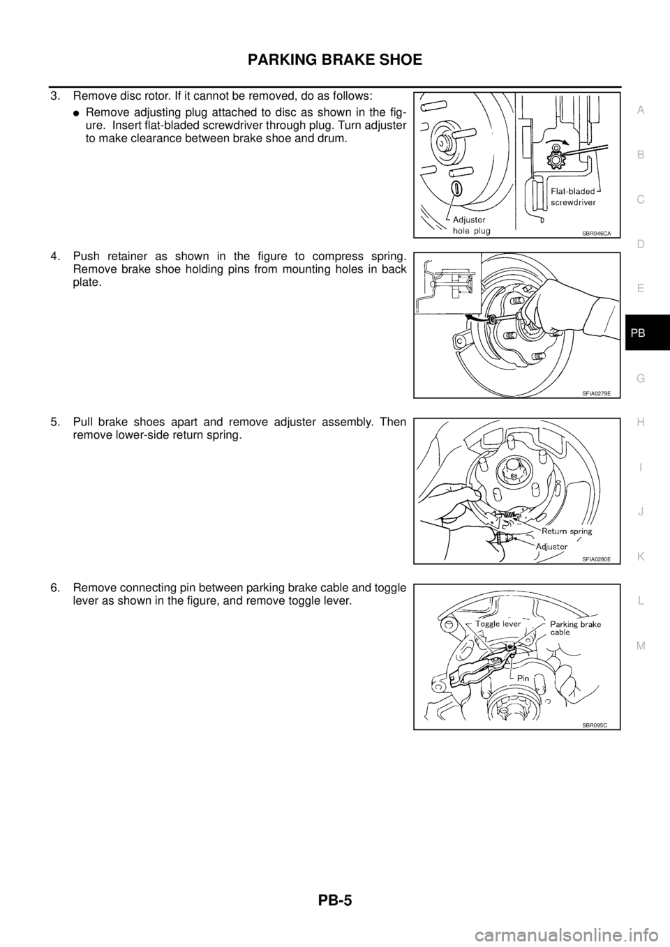
3. Remove disc rotor. If it cannot be removed, do as follows:
�Remove adjusting plug attached to disc as shown in the fig-
ure. Insert flat-bladed screwdriver through plug. Turn adjuster
to make clearance between brake shoe and drum.
4. Push retainer as shown in the figure to compress spring.
Remove brake shoe holding pins from mounting holes in back
plate.
5. Pull brake shoes apart and remove adjuster assembly. Then
remove lower-side return spring.
6. Remove connecting pin between parking brake cable and toggle
lever as shown in the figure, and remove toggle lever.
SBR046CA
SFIA0279E
SFIA0280E
SBR095C
Page 3044 of 4555
PB-6
PARKING BRAKE SHOE
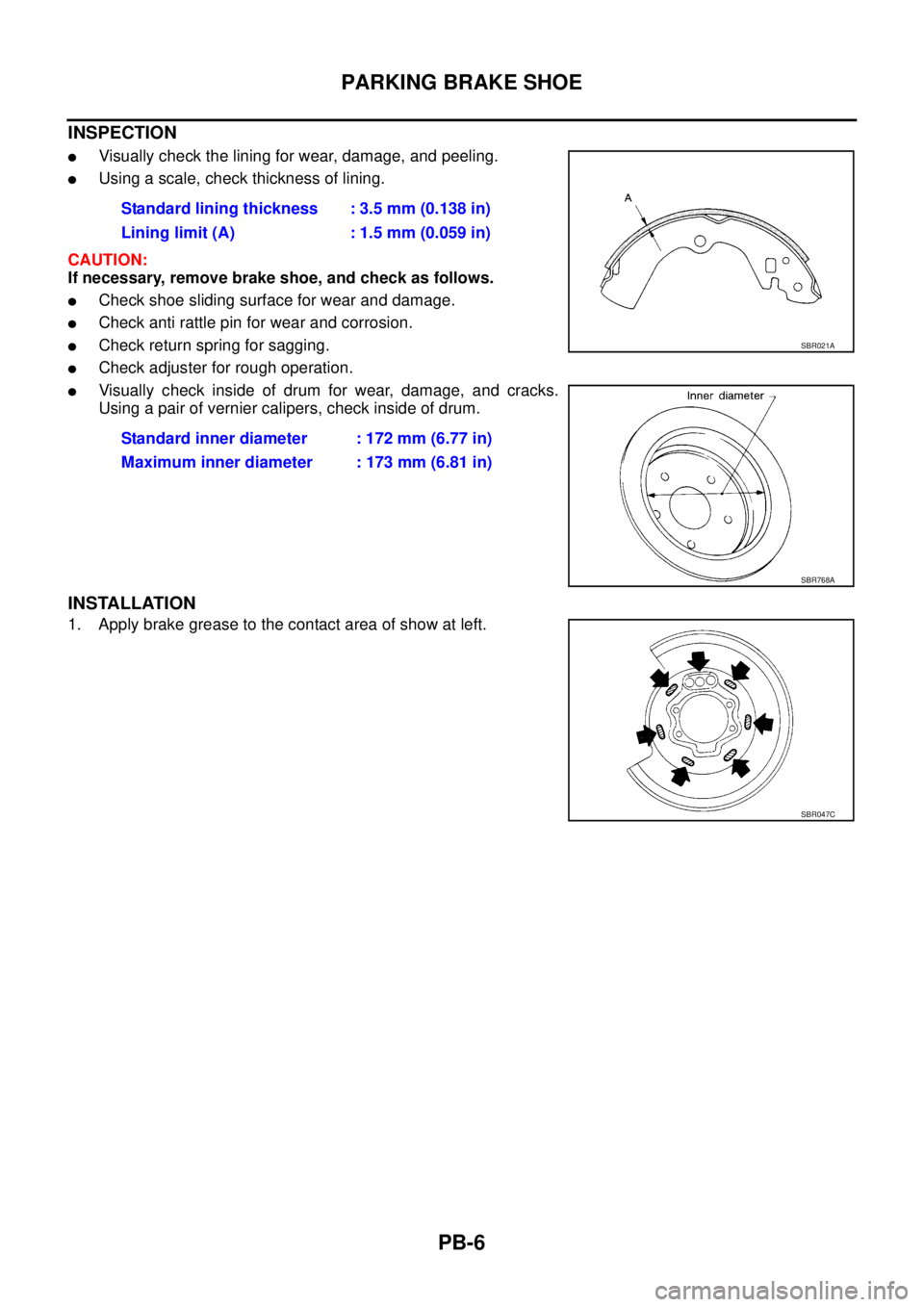
INSPECTION
�Visually check the lining for wear, damage, and peeling.
�Using a scale, check thickness of lining.
CAUTION:
If necessary, remove brake shoe, and check as follows.
�Check shoe sliding surface for wear and damage.
�Check anti rattle pin for wear and corrosion.
�Check return spring for sagging.
�Check adjuster for rough operation.
�Visually check inside of drum for wear, damage, and cracks.
Using a pair of vernier calipers, check inside of drum.
INSTALLATION
1. Apply brake grease to the contact area of show at left.Standard lining thickness : 3.5 mm (0.138 in)
Lining limit (A) : 1.5 mm (0.059 in)
Standard inner diameter : 172 mm (6.77 in)
Maximum inner diameter : 173 mm (6.81 in)
SBR021A
SBR768A
SBR047C