Page 3656 of 4555
BL-74
MULTI-REMOTE CONTROL SYSTEM
MULTI-REMOTE CONTROL SYSTEMPFP:28596
Component Parts and Harness Connector LocationEIS001RD
PIIA0585E
Page 3657 of 4555

MULTI-REMOTE CONTROL SYSTEM
BL-75
C
D
E
F
G
H
J
K
L
MA
B
BL
System DescriptionEIS001RE
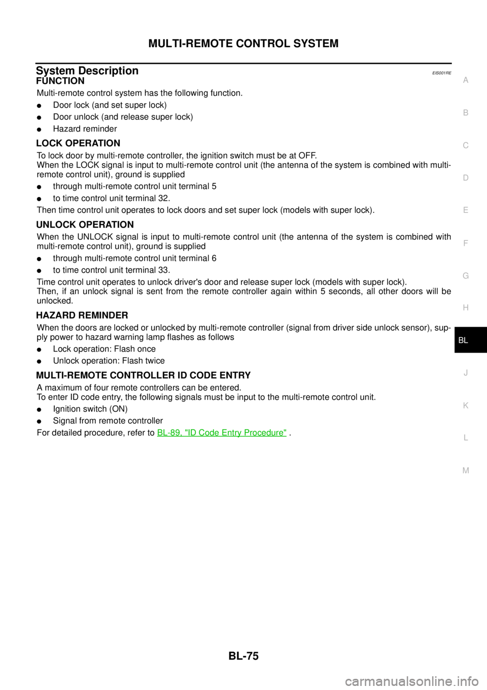
FUNCTION
Multi-remote control system has the following function.
�Door lock (and set super lock)
�Door unlock (and release super lock)
�Hazard reminder
LOCK OPERATION
To lock door by multi-remote controller, the ignition switch must be at OFF.
When the LOCK signal is input to multi-remote control unit (the antenna of the system is combined with multi-
remote control unit), ground is supplied
�through multi-remote control unit terminal 5
�to time control unit terminal 32.
Then time control unit operates to lock doors and set super lock (models with super lock).
UNLOCK OPERATION
When the UNLOCK signal is input to multi-remote control unit (the antenna of the system is combined with
multi-remote control unit), ground is supplied
�through multi-remote control unit terminal 6
�to time control unit terminal 33.
Time control unit operates to unlock driver's door and release super lock (models with super lock).
Then, if an unlock signal is sent from the remote controller again within 5 seconds, all other doors will be
unlocked.
HAZARD REMINDER
When the doors are locked or unlocked by multi-remote controller (signal from driver side unlock sensor), sup-
ply power to hazard warning lamp flashes as follows
�Lock operation: Flash once
�Unlock operation: Flash twice
MULTI-REMOTE CONTROLLER ID CODE ENTRY
A maximum of four remote controllers can be entered.
To enter ID code entry, the following signals must be input to the multi-remote control unit.
�Ignition switch (ON)
�Signal from remote controller
For detailed procedure, refer to BL-89, "
ID Code Entry Procedure" .
Page 3658 of 4555
BL-76
MULTI-REMOTE CONTROL SYSTEM
SchematicEIS008NF
TIWB0029E
Page 3659 of 4555
MULTI-REMOTE CONTROL SYSTEM
BL-77
C
D
E
F
G
H
J
K
L
MA
B
BL
Wiring Diagram — MULTI —EIS001RF
TIWA0475E
Page 3660 of 4555
BL-78
MULTI-REMOTE CONTROL SYSTEM
TIWA0476E
Page 3661 of 4555
MULTI-REMOTE CONTROL SYSTEM
BL-79
C
D
E
F
G
H
J
K
L
MA
B
BL
TIWB0030E
Page 3662 of 4555

BL-80
MULTI-REMOTE CONTROL SYSTEM
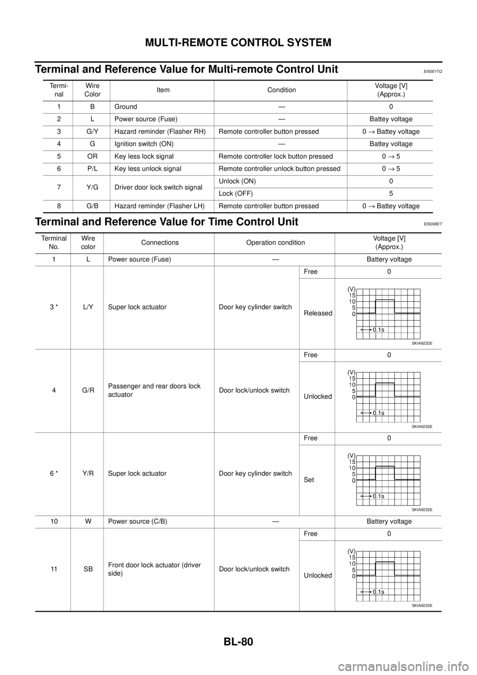
Terminal and Reference Value for Multi-remote Control UnitEIS001TQ
Terminal and Reference Value for Time Control UnitEIS008ET
Termi-
nalWire
ColorItem ConditionVoltage [V]
(Approx.)
1 B Ground — 0
2 L Power source (Fuse) — Battey voltage
3 G/Y Hazard reminder (Flasher RH) Remote controller button pressed 0 → Battey voltage
4 G Ignition switch (ON) — Battey voltage
5 OR Key less lock signal Remote controller lock button pressed 0 → 5
6 P/L Key less unlock signal Remote controller unlock button pressed 0 → 5
7 Y/G Driver door lock switch signalUnlock (ON) 0
Lock (OFF) 5
8 G/B Hazard reminder (Flasher LH) Remote controller button pressed 0 → Battey voltage
Terminal
No.Wire
colorConnections Operation conditionVoltage [V]
(Approx.)
1 L Power source (Fuse) — Battery voltage
3 * L/Y Super lock actuator Door key cylinder switchFree 0
Released
4 G/RPassenger and rear doors lock
actuatorDoor lock/unlock switchFree 0
Unlocked
6 * Y/R Super lock actuator Door key cylinder switchFree 0
Set
10 W Power source (C/B) — Battery voltage
11 S BFront door lock actuator (driver
side)Door lock/unlock switchFree 0
Unlocked
SKIA9232E
SKIA9232E
SKIA9232E
SKIA9232E
Page 3663 of 4555

MULTI-REMOTE CONTROL SYSTEM
BL-81
C
D
E
F
G
H
J
K
L
MA
B
BL
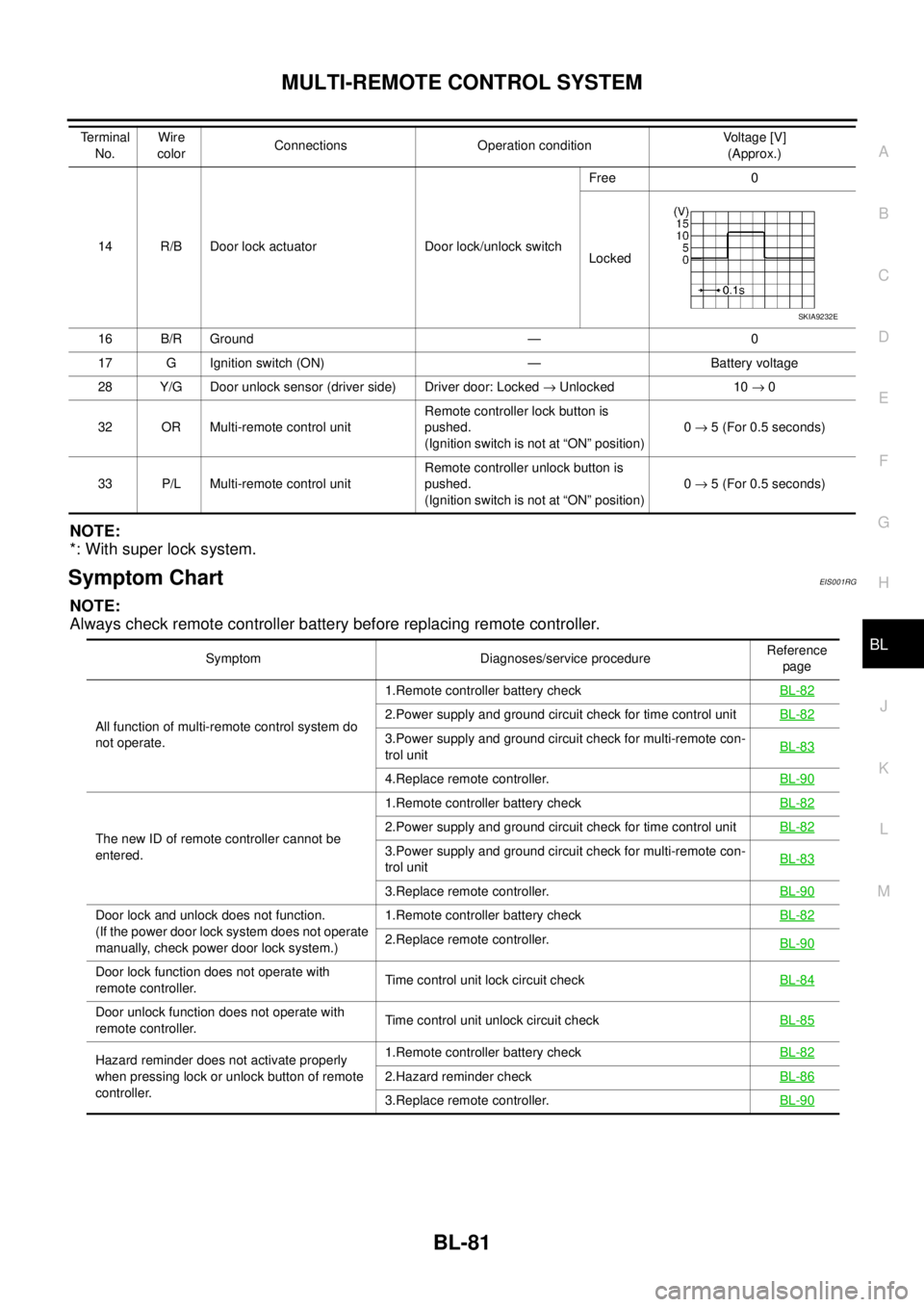
NOTE:
*: With super lock system.
Symptom ChartEIS001RG
NOTE:
Always check remote controller battery before replacing remote controller.
14 R/B Door lock actuator Door lock/unlock switchFree 0
Locked
16 B/R Ground — 0
17 G Ignition switch (ON) — Battery voltage
28 Y/G Door unlock sensor (driver side) Driver door: Locked → Unlocked 10 → 0
32 OR Multi-remote control unitRemote controller lock button is
pushed.
(Ignition switch is not at “ON” position)0 → 5 (For 0.5 seconds)
33 P/L Multi-remote control unitRemote controller unlock button is
pushed.
(Ignition switch is not at “ON” position)0 → 5 (For 0.5 seconds) Te r m i n a l
No.Wire
colorConnections Operation conditionVoltage [V]
(Approx.)
SKIA9232E
Symptom Diagnoses/service procedureReference
page
All function of multi-remote control system do
not operate.1.Remote controller battery checkBL-82
2.Power supply and ground circuit check for time control unitBL-82
3.Power supply and ground circuit check for multi-remote con-
trol unitBL-83
4.Replace remote controller.BL-90
The new ID of remote controller cannot be
entered.1.Remote controller battery checkBL-822.Power supply and ground circuit check for time control unitBL-82
3.Power supply and ground circuit check for multi-remote con-
trol unitBL-83
3.Replace remote controller.BL-90
Door lock and unlock does not function.
(If the power door lock system does not operate
manually, check power door lock system.)1.Remote controller battery check BL-82
2.Replace remote controller.
BL-90
Door lock function does not operate with
remote controller.Time control unit lock circuit checkBL-84
Door unlock function does not operate with
remote controller.Time control unit unlock circuit check BL-85
Hazard reminder does not activate properly
when pressing lock or unlock button of remote
controller.1.Remote controller battery check BL-82
2.Hazard reminder checkBL-86
3.Replace remote controller.BL-90