Page 4079 of 4555

HEADLAMP AIMING CONTROL (AUTO)
LT-83
C
D
E
F
G
H
I
J
L
MA
B
LT
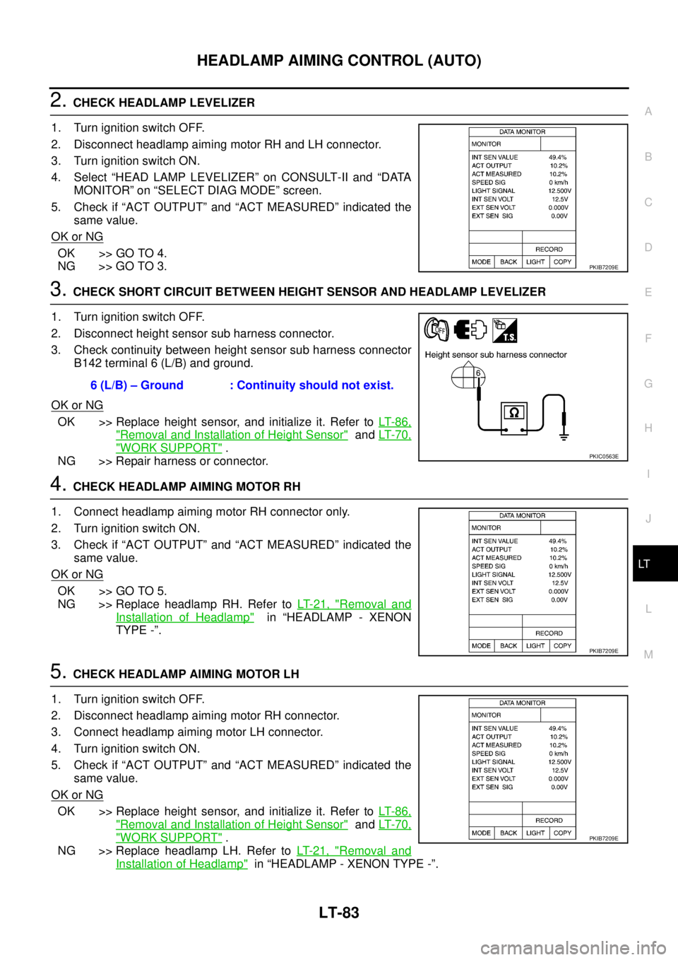
2. CHECK HEADLAMP LEVELIZER
1. Turn ignition switch OFF.
2. Disconnect headlamp aiming motor RH and LH connector.
3. Turn ignition switch ON.
4. Select “HEAD LAMP LEVELIZER” on CONSULT-II and “DATA
MONITOR” on “SELECT DIAG MODE” screen.
5. Check if “ACT OUTPUT” and “ACT MEASURED” indicated the
same value.
OK or NG
OK >> GO TO 4.
NG >> GO TO 3.
3. CHECK SHORT CIRCUIT BETWEEN HEIGHT SENSOR AND HEADLAMP LEVELIZER
1. Turn ignition switch OFF.
2. Disconnect height sensor sub harness connector.
3. Check continuity between height sensor sub harness connector
B142 terminal 6 (L/B) and ground.
OK or NG
OK >> Replace height sensor, and initialize it. Refer to LT- 8 6 ,
"Removal and Installation of Height Sensor" and LT- 7 0 ,
"WORK SUPPORT" .
NG >> Repair harness or connector.
4. CHECK HEADLAMP AIMING MOTOR RH
1. Connect headlamp aiming motor RH connector only.
2. Turn ignition switch ON.
3. Check if “ACT OUTPUT” and “ACT MEASURED” indicated the
same value.
OK or NG
OK >> GO TO 5.
NG >> Replace headlamp RH. Refer to LT- 2 1 , "
Removal and
Installation of Headlamp" in “HEADLAMP - XENON
TYPE -”.
5. CHECK HEADLAMP AIMING MOTOR LH
1. Turn ignition switch OFF.
2. Disconnect headlamp aiming motor RH connector.
3. Connect headlamp aiming motor LH connector.
4. Turn ignition switch ON.
5. Check if “ACT OUTPUT” and “ACT MEASURED” indicated the
same value.
OK or NG
OK >> Replace height sensor, and initialize it. Refer to LT- 8 6 ,
"Removal and Installation of Height Sensor" and LT- 7 0 ,
"WORK SUPPORT" .
NG >> Replace headlamp LH. Refer to LT- 2 1 , "
Removal and
Installation of Headlamp" in “HEADLAMP - XENON TYPE -”.
PKIB7209E
6 (L/B) – Ground : Continuity should not exist.
PKIC0563E
PKIB7209E
PKIB7209E
Page 4080 of 4555
![NISSAN X-TRAIL 2005 Service Repair Manual LT-84
HEADLAMP AIMING CONTROL (AUTO)
DTC B2088 [SHORT TO BATTERY]EKS00N6G
1. CHECK HEIGHT SENSOR
1. Select “HEAD LAMP LEVELIZER” on CONSULT-II and “DATA
MONITOR” on “SELECT DIAG MODE” sc NISSAN X-TRAIL 2005 Service Repair Manual LT-84
HEADLAMP AIMING CONTROL (AUTO)
DTC B2088 [SHORT TO BATTERY]EKS00N6G
1. CHECK HEIGHT SENSOR
1. Select “HEAD LAMP LEVELIZER” on CONSULT-II and “DATA
MONITOR” on “SELECT DIAG MODE” sc](/manual-img/5/57403/w960_57403-4079.png)
LT-84
HEADLAMP AIMING CONTROL (AUTO)
DTC B2088 [SHORT TO BATTERY]EKS00N6G
1. CHECK HEIGHT SENSOR
1. Select “HEAD LAMP LEVELIZER” on CONSULT-II and “DATA
MONITOR” on “SELECT DIAG MODE” screen.
2. Lighting switch is turned 1ST position.
3. Check if “ACT OUTPUT” and “ACT MEASURED” indicated the
same value.
NOTE:
If shorted to battery, “ACT MEASURED” indicates approx.
100%.
OK or NG
OK >> Erase the self-diagnosis and perform the self-diagnosis
again.
�[B2088] is displayed again: Replace height sensor, and initialize it. Refer to LT- 8 6 , "Removal
and Installation of Height Sensor" and LT- 7 0 , "WORK SUPPORT" .
�NO DTC is displayed: INSPECTION END
NG >> GO TO 2.
2. CHECK HEADLAMP LEVELIZER
1. Turn ignition switch OFF.
2. Lighting switch is turned OFF position.
3. Disconnect headlamp aiming motor RH and LH connector.
4. Select “HEAD LAMP LEVELIZER” on CONSULT-II and “DATA
MONITOR” on “SELECT DIAG MODE” screen.
5. Lighting switch is turned 1ST position.
6. Check if “ACT OUTPUT” and “ACT MEASURED” indicated the
same value.
OK or NG
OK >> GO TO 4.
NG >> GO TO 3.
3. CHECK SHORT CIRCUIT BETWEEN HEIGHT SENSOR AND HEADLAMP LEVELIZER
1. Turn ignition switch OFF.
2. Lighting switch is turned OFF position.
3. Disconnect height sensor sub harness connector.
4. Turn ignition switch ON.
5. Check voltage between height sensor sub harness connector
B142 terminal 6 (L/B) and ground.
OK or NG
OK >> Replace height sensor, and initialize it. Refer to LT- 8 6 ,
"Removal and Installation of Height Sensor" and LT- 7 0 ,
"WORK SUPPORT" .
NG >> Repair harness or connector.
PKIB7209E
PKIB7209E
6 (L/B) – Ground : Approx. 0 V
PKIC0564E
Page 4081 of 4555
HEADLAMP AIMING CONTROL (AUTO)
LT-85
C
D
E
F
G
H
I
J
L
MA
B
LT
4. CHECK HEADLAMP AIMING MOTOR RH
1. Connect headlamp aiming motor RH connector only.
2. Turn ignition switch ON.
3. Check if “ACT OUTPUT” and “ACT MEASURED” indicated the
same value.
OK or NG
OK >> GO TO 5.
NG >> Replace headlamp RH. Refer to LT- 2 1 , "
Removal and
Installation of Headlamp" in HEADLAMP - XENON
TYPE -.
5. CHECK HEADLAMP AIMING MOTOR LH
1. Turn ignition switch OFF.
2. Disconnect headlamp aiming motor RH connector.
3. Connect headlamp aiming motor LH connector.
4. Turn ignition switch ON.
5. Check if “ACT OUTPUT” and “ACT MEASURED” indicated the
same value.
OK or NG
OK >> Replace height sensor, and initialize it. Refer to LT- 8 6 ,
"Removal and Installation of Height Sensor" and LT- 7 0 ,
"WORK SUPPORT" .
NG >> Replace headlamp LH. Refer to LT- 2 1 , "
Removal and
Installation of Headlamp" in HEADLAMP - XENON TYPE -.
PKIB7209E
PKIB7209E
Page 4082 of 4555
LT-86
HEADLAMP AIMING CONTROL (AUTO)
Removal and Installation of Height SensorEKS00N6H
REMOVAL
1. Turn ignition switch OFF.
2. Disconnect the battery cable from the negative terminal or remove power fuse.
3. Lift-up the vehicle.
4. Disconnect height sensor sub harness connector.
5. Remove linkage mounting bolt.
6. Remove height sensor mounting bolt and remove height sensor
from vehicle.
INSTALLATION
Installation is the reverse order of removal.
NOTE:
Initialize whenever replacing the height sensor. Refer to LT- 7 0 , "
WORK SUPPORT" .
PKIC0424E
Height sensor mounting bolt : 5.5 N·m (0.56 kg-m, 49 in-lb)
Linkage mounting bolt : 5.5 N·m (0.56 kg-m, 49 in-lb)
Page 4129 of 4555

INTERIOR ROOM LAMP
LT-133
C
D
E
F
G
H
I
J
L
MA
B
LT
When map lamp switch is ON, ground is supplied (with sunroof)
�to map lamp terminal 2
�through ground M27 and M70.
INTERIOR ROOM LAMP TIMER OPERATION
When interior room lamp and map lamp (with sunroof) switch is in the DOOR position, the time control unit
keeps the interior room lamp and map lamp (with sunroof) illuminated for about 30 seconds when
�unlock signal is supplied from driver's door unlock sensor while all doors are closed and key is out of igni-
tion key cylinder
�key is removed from ignition key cylinder while all doors are closed
�driver's door is opened and then closed while key is out of the ignition key cylinder. (However, if the
driver's door is closed with the key inserted in the ignition key cylinder after the driver's door is opened
with the key removed, the timer is operated.)
The timer is canceled when
�driver's door is locked,
�driver's door is opened, or
�ignition switch is turned ON.
ON-OFF CONTROL
When the driver’s door, passenger’s door, rear LH door or rear RH door is opened, the interior room lamp and
map lamp (with sunroof) turns on while the interior room lamp and map lamp (with sunroof) switch is in the
DOOR position.
Page 4135 of 4555

INTERIOR ROOM LAMP
LT-139
C
D
E
F
G
H
I
J
L
MA
B
LT
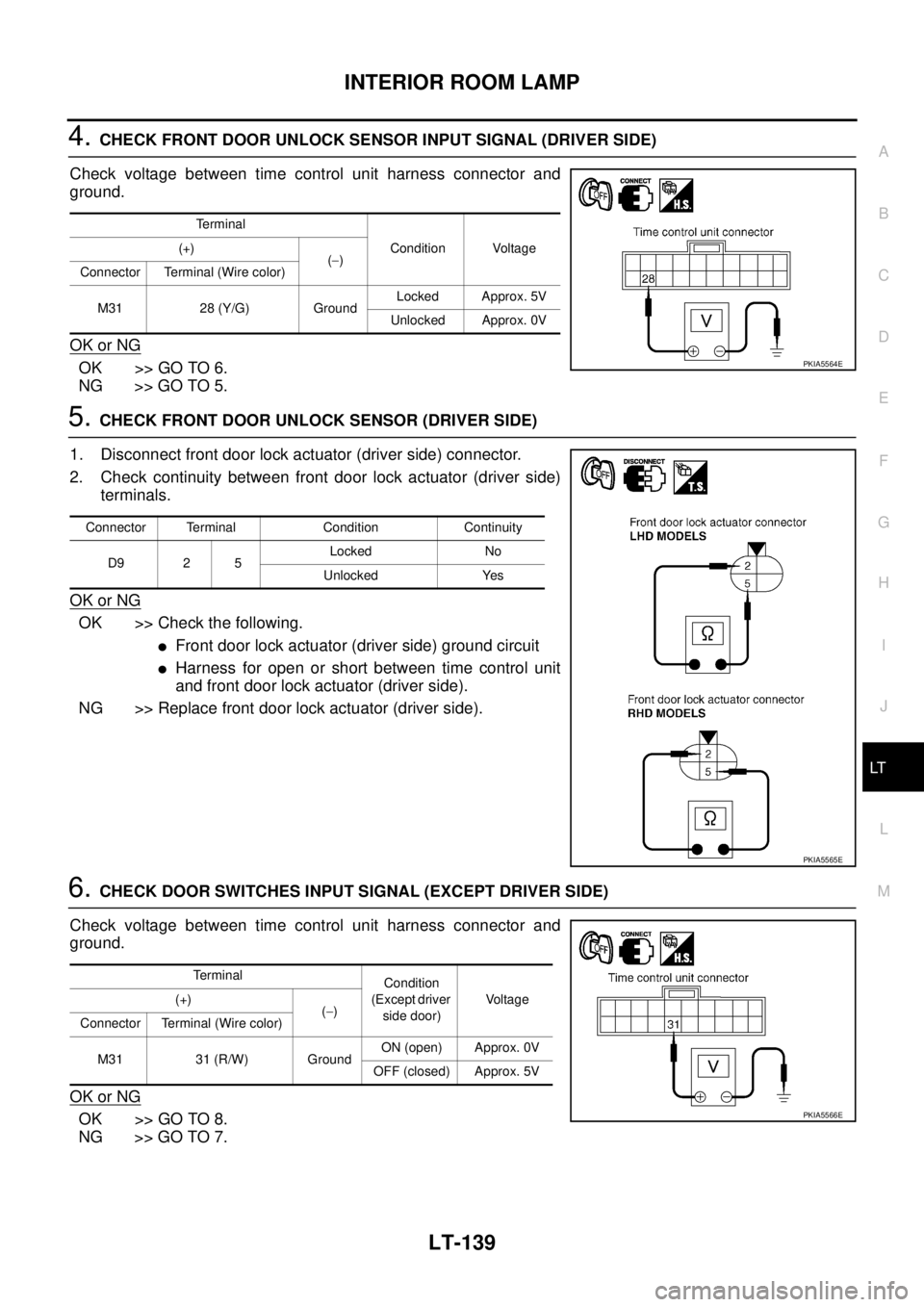
4. CHECK FRONT DOOR UNLOCK SENSOR INPUT SIGNAL (DRIVER SIDE)
Check voltage between time control unit harness connector and
ground.
OK or NG
OK >> GO TO 6.
NG >> GO TO 5.
5. CHECK FRONT DOOR UNLOCK SENSOR (DRIVER SIDE)
1. Disconnect front door lock actuator (driver side) connector.
2. Check continuity between front door lock actuator (driver side)
terminals.
OK or NG
OK >> Check the following.
�Front door lock actuator (driver side) ground circuit
�Harness for open or short between time control unit
and front door lock actuator (driver side).
NG >> Replace front door lock actuator (driver side).
6. CHECK DOOR SWITCHES INPUT SIGNAL (EXCEPT DRIVER SIDE)
Check voltage between time control unit harness connector and
ground.
OK or NG
OK >> GO TO 8.
NG >> GO TO 7.
Terminal
Condition Voltage (+)
(−)
Connector Terminal (Wire color)
M31 28 (Y/G) GroundLocked Approx. 5V
Unlocked Approx. 0V
PKIA5564E
Connector Terminal Condition Continuity
D9 2 5Locked No
Unlocked Yes
PKIA5565E
Terminal
Condition
(Except driver
side door)Vo l ta g e (+)
(−)
Connector Terminal (Wire color)
M31 31 (R/W) GroundON (open) Approx. 0V
OFF (closed) Approx. 5V
PKIA5566E
Page 4138 of 4555

LT-142
INTERIOR ROOM LAMP
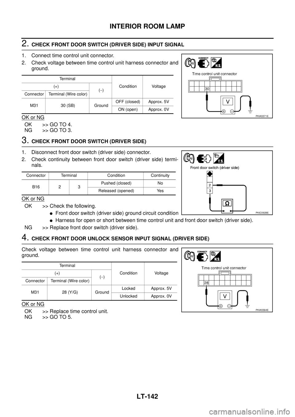
2. CHECK FRONT DOOR SWITCH (DRIVER SIDE) INPUT SIGNAL
1. Connect time control unit connector.
2. Check voltage between time control unit harness connector and
ground.
OK or NG
OK >> GO TO 4.
NG >> GO TO 3.
3. CHECK FRONT DOOR SWITCH (DRIVER SIDE)
1. Disconnect front door switch (driver side) connector.
2. Check continuity between front door switch (driver side) termi-
nals.
OK or NG
OK >> Check the following.
�Front door switch (driver side) ground circuit condition
�Harness for open or short between time control unit and front door switch (driver side).
NG >> Replace front door switch (driver side).
4. CHECK FRONT DOOR UNLOCK SENSOR INPUT SIGNAL (DRIVER SIDE)
Check voltage between time control unit harness connector and
ground.
OK or NG
OK >> Replace time control unit.
NG >> GO TO 5.
Terminal
Condition Voltage (+)
(−)
Connector Terminal (Wire color)
M31 30 (SB) GroundOFF (closed) Approx. 5V
ON (open) Approx. 0V
PKIA5571E
Connector Terminal Condition Continuity
B16 2 3Pushed (closed) No
Released (opened) Yes
PKIC0928E
Terminal
Condition Voltage (+)
(−)
Connector Terminal (Wire color)
M31 28 (Y/G) GroundLocked Approx. 5V
Unlocked Approx. 0V
PKIA5564E
Page 4139 of 4555

INTERIOR ROOM LAMP
LT-143
C
D
E
F
G
H
I
J
L
MA
B
LT
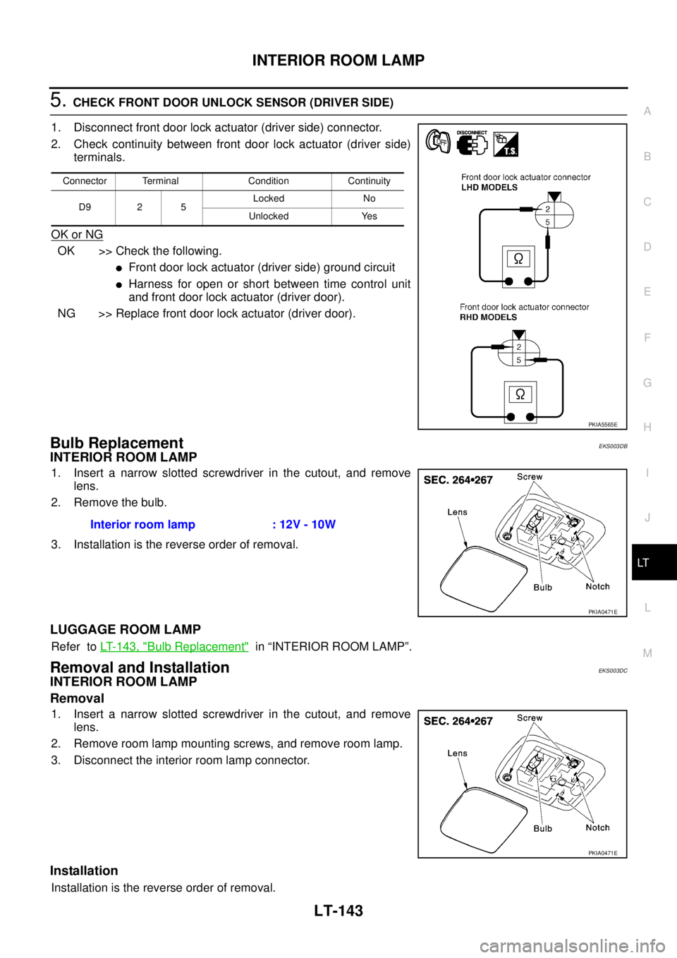
5. CHECK FRONT DOOR UNLOCK SENSOR (DRIVER SIDE)
1. Disconnect front door lock actuator (driver side) connector.
2. Check continuity between front door lock actuator (driver side)
terminals.
OK or NG
OK >> Check the following.
�Front door lock actuator (driver side) ground circuit
�Harness for open or short between time control unit
and front door lock actuator (driver door).
NG >> Replace front door lock actuator (driver door).
Bulb Replacement EKS003DB
INTERIOR ROOM LAMP
1. Insert a narrow slotted screwdriver in the cutout, and remove
lens.
2. Remove the bulb.
3. Installation is the reverse order of removal.
LUGGAGE ROOM LAMP
Refer to LT- 1 4 3 , "Bulb Replacement" in “INTERIOR ROOM LAMP”.
Removal and InstallationEKS003DC
INTERIOR ROOM LAMP
Removal
1. Insert a narrow slotted screwdriver in the cutout, and remove
lens.
2. Remove room lamp mounting screws, and remove room lamp.
3. Disconnect the interior room lamp connector.
Installation
Installation is the reverse order of removal.
Connector Terminal Condition Continuity
D9 2 5Locked No
Unlocked Yes
PKIA5565E
Interior room lamp : 12V - 10W
PKIA0471E
PKIA0471E