Page 3552 of 4555
![NISSAN X-TRAIL 2005 Service Repair Manual SRS-20
TROUBLE DIAGNOSIS
a. Touch “SELF-DIAG [CURRENT]”.
�Diagnostic code is displayed on “SELF-DIAG [CURRENT]”.
i. If the malfunction is displayed in the “SRS Operation Check” (Air bag](/manual-img/5/57403/w960_57403-3551.png "NISSAN X-TRAIL 2005 Service Repair Manual SRS-20
TROUBLE DIAGNOSIS
a. Touch “SELF-DIAG [CURRENT]”.
�Diagnostic code is displayed on “SELF-DIAG [CURRENT]”.
i. If the malfunction is displayed in the “SRS Operation Check” (Air bag")
SRS-20
TROUBLE DIAGNOSIS
a. Touch “SELF-DIAG [CURRENT]”.
�Diagnostic code is displayed on “SELF-DIAG [CURRENT]”.
i. If the malfunction is displayed in the “SRS Operation Check” (Air bag warning lamp blinking) but no mal-
function is displayed in the “SELF-DIAG [CURRENT]”, the following possibilities shall be checked. Refer
to SRS-21, "
DIAGNOSTIC PROCEDURE 3" .
�Low battery voltage (Less than 9 V)
�After the malfunction part is repaired, the diagnosis results in “SELF-DIAG [PAST]” has not been
erased.
�An intermittent malfunction has been stored in the past.
NOTE:
Intermittent malfunction is a malfunction that has occurred once in the past, but soon recovered.
b. Touch “SELF-DIAG [PAST]”.
�The diagnostic code is displayed until erasing the memory in
the “SELF-DIAG [CURRENT]”.
c. Touch “TROUBLE DIAG RECORD”.
�The diagnosis results (malfunction parts stored in the diagno-
sis sensor unit) stored in the self-diagnosis results are dis-
played.
�The memory of “TROUBLE DIAG RECORD” cannot be
erased.
7. Each diagnostic code is displayed. Refer to SRS-22, "
Diagnostic
Code Chart" .
8. Touch “PRINT”, if required.
9. Based on each diagnosis result, repair or replace the malfunc-
tion parts.
CAUTION:
Be sure to start the work after the following steps. Turn the
ignition switch OFF, and disconnect both battery cables.
Then wait for at least 3 minutes.
SHIA0203E
SHIA0181E
SHIA0182E
SHIA0180E
Page 3553 of 4555
![NISSAN X-TRAIL 2005 Service Repair Manual TROUBLE DIAGNOSIS
SRS-21
C
D
E
F
G
I
J
K
L
MA
B
SRS
10. After repairing the malfunction, touch “SELF-DIAG [CURRENT]”
to check that “No DTC IS DETECTED” is displayed.
�After checking the disp](/manual-img/5/57403/w960_57403-3552.png "NISSAN X-TRAIL 2005 Service Repair Manual TROUBLE DIAGNOSIS
SRS-21
C
D
E
F
G
I
J
K
L
MA
B
SRS
10. After repairing the malfunction, touch “SELF-DIAG [CURRENT]”
to check that “No DTC IS DETECTED” is displayed.
�After checking the disp")
TROUBLE DIAGNOSIS
SRS-21
C
D
E
F
G
I
J
K
L
MA
B
SRS
10. After repairing the malfunction, touch “SELF-DIAG [CURRENT]”
to check that “No DTC IS DETECTED” is displayed.
�After checking the display, touch “ERASE”.
�If any malfunction is displayed on “SELF-DIAG [CURRENT]”,
repair or replace the malfunctioning again.
11. Touch “BACK” key of CONSULT-II to “SELECT SYSTEM”
screen. Touch “SELF-DIAG [PAST]”.
12. Check that no malfunction is detected on “SELF-DIAG [PAST]”.
�If any malfunction is deployed, Touch “ERASE” in the “SELF-
DIAG [CURRENT]” screen, and check the display.
13. Turn ignition switch OFF, then turn off and disconnect CONSULT-II.
14. Turn ignition switch ON, and check the system with the SRS air bag warning lamp (User mode).
15. Check that no malfunction is detected. Now the diagnosis is complete.
DIAGNOSTIC PROCEDURE 3
Inspecting SRS Malfunctioning Record
If any malfunction is detected in “SRS Operation Check”, but no malfunction is detected in “SELF-DIAG [CUR-
RENT]” on CONSULT-II, carry out the following steps.
1. CHECK BATTERY VOLTAGE
Disconnect both battery cables and check that the battery voltage is 9 V or more.
OK or NG
OK >> GO TO 2.
NG >> Charge the battery.
2. CONSIDER POSSIBILITY OF NOT ERASING SELF-DIAGNOSTIC RESULT AFTER REPAIRING.
Is it the first time for maintenance of SRS?
YES or NO
YES >> GO TO 3.
NO >> Erase the self-diagnostic results, and Check the “SRS Operation Check”. Refer to SRS-17, "
SRS
Operation Check" .
3. CHECK “SELF-DIAG [PAST]” BY CONSULT-II
Store the memory in “SELF-DIAG [PAST]”.
YES or NO
YES >> Repair the part of “SELF-DIAG[PAST]”.
NO >> Check the “TROUBLE DIAG RECORD”, and then repair it. Refer to SRS-22, "
Diagnostic Code
Chart" .
SRS701
SRS702
Page 3556 of 4555
SRS-24
TROUBLE DIAGNOSIS
Trouble Diagnosis without CONSULT-IIEHS000OA
DIAGNOSTIC PROCEDURE 4
CAUTION:
SRS will not enter diagnosis mode if no malfunction is detected in user mode.
1. Turn ignition switch ON.
2. After “AIR BAG” warning lamp lights for 7 seconds, turn ignition switch OFF within 1 second.
3. Wait more than 3 seconds.
4. Repeat the steps 1 to 3 two times.
5. Turn ignition switch ON.
6. Compare the number of flashes to Air Bag Warning Lamp Flash Code.
7. Turn the ignition switch OFF, and disconnect both battery cables.
8. Repair the system as outlined by the “REPAIR ORDER” in “Warning Lamp Flash Code Chart” that corre-
sponds to flash code.
9. After the repairing of malfunction, connect both battery cables, and turn the ignition switch ON.
10. Check that no malfunction is detected.
Page 3560 of 4555

SRS-28
TROUBLE DIAGNOSIS
Trouble Diagnosis: “AIR BAG” Warning Lamp Does Not Turn OFFEHS000OB
DIAGNOSTIC PROCEDURE 5
1. CHECK THE DEPLOYMENT OF AIR BAG MODULE
Is air bag module deployed?
YES or NO
YES >> Refer to SRS-48, "COLLISION DIAGNOSIS" .
NO >> GO TO 2.
2. CHECK THE AIR BAG FUSE
Check 10A fuse [No. 9, located in fuse block (J/B)].
Refer to PG-2, "
POWER SUPPLY ROUTING" .
OK or NG
OK >> GO TO 4.
NG >> GO TO 3.
3. CHECK AIR BAG FUSE AGAIN
Replace “AIR BAG” fuse and turn ignition switch ON.
Is
“AIR BAG” fuse blown again?
YES >> Repair main harness.
NO >>INSPECTION END
4. CHECK DIAGNOSIS SENSOR UNIT
Connect CONSULT-II and touch “START”.
Is
“AIR BAG” displayed on CONSULT-ll?
YES >> GO TO 5.
NO >> Visually check the wiring harness connection of diagno-
sis sensor unit. If the harness connection check result is
OK, replace diagnosis sensor unit.
5. CHECK HARNESS CONNECTION
Is harness connection between warning lamp and diagnosis sensor unit OK?
OK or NG
OK >> Replace diagnosis sensor unit.
NG >> Connect “AIR BAG” warning lamp and diagnosis sensor unit connector properly. If “AIR BAG”
warning lamp still does not go off, replace harness.
SRS771
Page 3561 of 4555
TROUBLE DIAGNOSIS
SRS-29
C
D
E
F
G
I
J
K
L
MA
B
SRS
Trouble Diagnosis: “AIR BAG” Warning Lamp Does Not Turn ONEHS000OC
DIAGNOSTIC PROCEDURE 6
1. CHECK “METER” FUSE
Check 10A fuse [No. 11, located in fuse block (J/B)].
Refer to PG-2, "
POWER SUPPLY ROUTING" .
OK or NG
OK >> GO TO 3.
NG >> GO TO 2.
2. CHECK “METER” FUSE AGAIN
Replace meter fuse and turn ignition switch ON.
Is meter fuse blown again?
YES >> Repair the related harness.
NO >>INSPECTION END
3. CHECK HARNESS CONNECTION BETWEEN DIAGNOSIS SENSOR UNIT AND COMBINATION
METER
Disconnect diagnosis sensor unit connector and turn ignition switch ON.
Does
“AIR BAG” warning lamp turn ON?
YES >> Replace diagnosis sensor unit.
NO >> Replace combination meter assembly.
Page 3562 of 4555
SRS-30
DRIVER AIR BAG MODULE
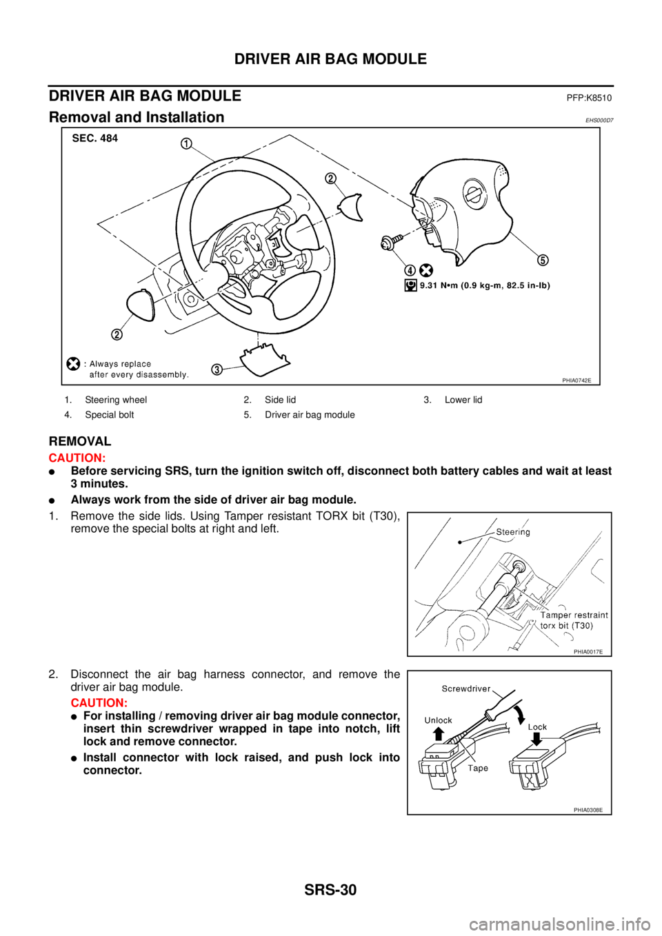
DRIVER AIR BAG MODULEPFP:K8510
Removal and InstallationEHS000D7
REMOVAL
CAUTION:
�Before servicing SRS, turn the ignition switch off, disconnect both battery cables and wait at least
3 minutes.
�Always work from the side of driver air bag module.
1. Remove the side lids. Using Tamper resistant TORX bit (T30),
remove the special bolts at right and left.
2. Disconnect the air bag harness connector, and remove the
driver air bag module.
CAUTION:
�For installing / removing driver air bag module connector,
insert thin screwdriver wrapped in tape into notch, lift
lock and remove connector.
�Install connector with lock raised, and push lock into
connector.
PHIA0742E
1. Steering wheel 2. Side lid 3. Lower lid
4. Special bolt 5. Driver air bag module
PHIA0017E
PHIA0308E
Page 3565 of 4555

SPIRAL CABLE
SRS-33
C
D
E
F
G
I
J
K
L
MA
B
SRS
SPIRAL CABLEPFP:25554
Removal and InstallationEHS000D8
REMOVAL
CAUTION:
Before servicing SRS, turn the ignition switch off, disconnect both battery cables and wait at least 3
minutes.
1. Remove driver air bag module. Refer to SRS-30, "
Removal and Installation" .
2. Set the steering wheel in the neutral position.
3. Remove steering column cover. Refer to IP-10, "
INSTRUMENT PANEL ASSEMBLY" .
4. Disconnect the horn connector and the driver air bag module connector.
CAUTION:
Do not tap or bump the steering wheel.
5. Remove steering wheel nut.
6. Remove steering wheel with steering wheel puller.
CAUTION:
Be careful not to over-tighten puller on steering wheel.
7. Remove the spiral cable fixing screws, and while pushing the upper plastic tab, remove the spiral cable.
CAUTION:
�Do not attempt to disassemble spiral cable.
�Do not apply lubricant to the spiral cable.
8. Remove the wiper washer switch and lighting switch from the spiral cable.
PHIA0024E
SRS676
Page 3567 of 4555

FRONT PASSENGER AIR BAG MODULE
SRS-35
C
D
E
F
G
I
J
K
L
MA
B
SRS
FRONT PASSENGER AIR BAG MODULEPFP:K8515
Removal and InstallationEHS000D9
REMOVAL
CAUTION:
�Before servicing SRS, turn the ignition switch off, disconnect both battery cables and wait at least
3 minutes.
�Always work from the side of or under front passenger air bag module.
1. Remove the glove box. Refer to IP-10, "
INSTRUMENT PANEL ASSEMBLY" .
2. Disconnect the front passenger air bag harness connector.
3. Remove front passenger air bag fixing bolts.
Use Tamper resistant TORX bit (T50) to remove TORX bolts
(T50) or Hex bolts.
4. Pull front passenger air bag module upward. Then remove front
passenger air bag module from instrument panel.
CAUTION:
�Always place front passenger air bag module with warning
label side facing upward.
�Do not insert any foreign objects (screwdriver, etc.) into
front passenger air bag module.
�Do not attempt to disassemble front passenger air bagmod-
ule.
�Do not use old bolts after removal; replace with new bolts.
�Replace front passenger air bag module if it has been
dropped or sustained an impact.
�Do not expose the front passenger air bag module to tem-
peratures exceeding 90°C (194°F).
�Do not allow oil, grease or water to come in contact with the front passenger air bag module.
�After front passenger air bag module inflates, the instrument panel assembly should be replaced.
PHIA0728E
PHIA0026E
SBF814E