Page 3457 of 4555

TIME CONTROL UNIT
BCS-3
C
D
E
F
G
H
I
J
L
MA
B
BCS
TIME CONTROL UNITPFP:28491
DescriptionEKS002ZU
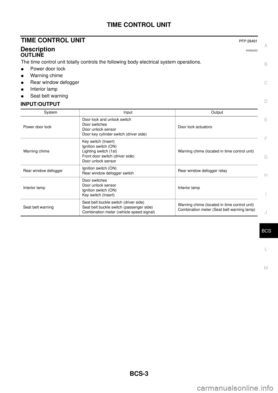
OUTLINE
The time control unit totally controls the following body electrical system operations.
�Power door lock
�Warning chime
�Rear window defogger
�Interior lamp
�Seat belt warning
INPUT/OUTPUT
System Input Output
Power door lockDoor lock and unlock switch
Door switches
Door unlock sensor
Door key cylinder switch (driver side)Door lock actuators
Warning chimeKey switch (Insert)
Ignition switch (ON)
Lighting switch (1st)
Front door switch (driver side)
Door unlock sensorWarning chime (located in time control unit)
Rear window defoggerIgnition switch (ON)
Rear window defogger switchRear window defogger relay
Interior lampDoor switches
Door unlock sensor
Ignition switch (ON)
Key switch (Insert)Interior lamp
Seat belt warningSeat belt buckle switch (driver side)
Seat belt buckle switch (passenger side)
Combination meter (vehicle speed signal)Warning chime (located in time control unit)
Combination meter (Seat belt warning lamp)
Page 3460 of 4555

BCS-6
TIME CONTROL UNIT
15 W/GSeat belt warning lamp
(passenger side)Seat belt warning lamp (passenger
side) is illuminated (seat belt is unfas-
tened).12V
Seat belt warning lamp (passenger
side) is not illuminated (seat belt is
unfastened).0V
16 B/R Ground — 0V
17 G Ignition switch (ON) — 12V
18 W/L Ignition key switch (Insert)Key inserted → key removed from Igni-
tion key cylinder12V → 0V
19 R/L Lighting switch 1ST, 2ND position: ON → OFF 12V → 0V
20 GY Door lock/unlock switch Neutral → Locked 5V → 0V
21 BR/WSeat belt buckle switch
(driver side)Seat belt buckle switch (driver side) is
unfastened.*20V
Seat belt buckle switch (driver side) is
fastened.*212V
22 G/ORSeat belt buckle switch
(passenger side)Seat belt buckle switch (passenger
side) is unfastened.0V
Seat belt buckle switch (passenger
side) is fastened.12V
23 PU Door lock/unlock switchNeutral → Door lock/Unlock switch is
pushed.5V → 0V
24 LG/RDoor key cylinder switch
(driver side)OFF (neutral) → ON (locked) 5V → 0V
25 GY/LDoor key cylinder switch
(driver side)OFF (neutral) → ON (unlocked) 5V → 0V
26 R/Y Interior room lampWhen interior room lamp is operated
using remote controller
(Lamp switch is “DOOR” position.)12V → 0V
27 G/W Rear window defogger relayOFF → ON
(Ignition key is “ON” position.)12V → 0V
28 Y/G Door unlock sensor (driver side) Driver door: Locked → Unlocked 10V → 0V
29*1 Y/LDoor unlock sensor
(passenger side)Passenger door: Locked → Unlocked 5V → 0V
30 SB Front door switch (driver side) OFF (closed) → ON (open) 5V → 0V
31 R/W Passenger and rear doors switch OFF (closed) → ON (open) 5V → 0V
32 OR Multi-remote control unitRemote controller lock button is pushed.
(Ignition switch is not “ON” position.)0V → 5V
33 P/L Multi-remote control unitRemote controller unlock button is
pushed.
(Ignition switch is not “ON” position.)0V → 5V
34 B/Y NATS release signal Ignition switch ON→OFF 0V → 5V Terminal
No.Wire
colorConnections Operation condition Voltage (Approximate values)
Page 3479 of 4555

POWER STEERING GEAR AND LINKAGE
PS-17
C
D
E
F
H
I
J
K
L
MA
B
PS
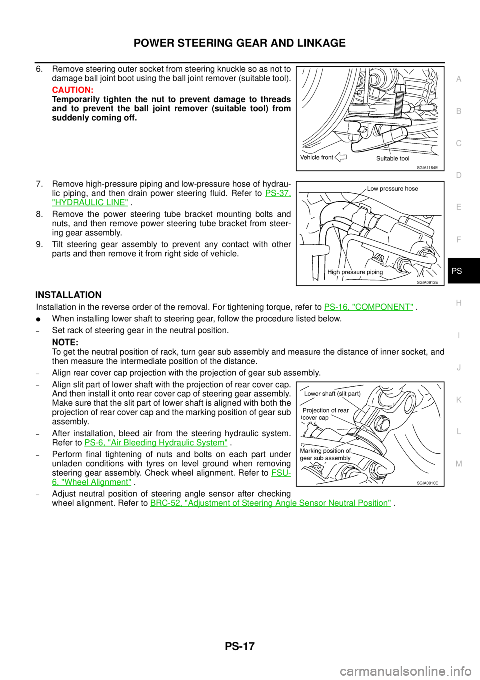
6. Remove steering outer socket from steering knuckle so as not to
damage ball joint boot using the ball joint remover (suitable tool).
CAUTION:
Temporarily tighten the nut to prevent damage to threads
and to prevent the ball joint remover (suitable tool) from
suddenly coming off.
7. Remove high-pressure piping and low-pressure hose of hydrau-
lic piping, and then drain power steering fluid. Refer to PS-37,
"HYDRAULIC LINE" .
8. Remove the power steering tube bracket mounting bolts and
nuts, and then remove power steering tube bracket from steer-
ing gear assembly.
9. Tilt steering gear assembly to prevent any contact with other
parts and then remove it from right side of vehicle.
INSTALLATION
Installation in the reverse order of the removal. For tightening torque, refer to PS-16, "COMPONENT" .
�When installing lower shaft to steering gear, follow the procedure listed below.
–Set rack of steering gear in the neutral position.
NOTE:
To get the neutral position of rack, turn gear sub assembly and measure the distance of inner socket, and
then measure the intermediate position of the distance.
–Align rear cover cap projection with the projection of gear sub assembly.
–Align slit part of lower shaft with the projection of rear cover cap.
And then install it onto rear cover cap of steering gear assembly.
Make sure that the slit part of lower shaft is aligned with both the
projection of rear cover cap and the marking position of gear sub
assembly.
–After installation, bleed air from the steering hydraulic system.
Refer to PS-6, "
Air Bleeding Hydraulic System" .
–Perform final tightening of nuts and bolts on each part under
unladen conditions with tyres on level ground when removing
steering gear assembly. Check wheel alignment. Refer to FSU-
6, "Wheel Alignment" .
–Adjust neutral position of steering angle sensor after checking
wheel alignment. Refer to BRC-52, "
Adjustment of Steering Angle Sensor Neutral Position" .
SGIA1164E
SGIA0912E
SGIA0910E
Page 3499 of 4555
HYDRAULIC LINE
PS-37
C
D
E
F
H
I
J
K
L
MA
B
PS
HYDRAULIC LINEPFP:49721
ComponentEGS0004O
CAUTION:
Securely insert harness connector to pressure sensor.
QR20DE LH MODEL
SGIA0944E
Page 3500 of 4555
PS-38
HYDRAULIC LINE
QR20DE RH MODEL
1. Reservoir tank 2. Suction hose 3. High-pressure hose
4. Oil pump assembly 5. Steering gear assembly 6. Pressure sensor
7. O-ring 8. Copper washer 9. Eye-joint (assembled to high-pres-
sure side hose)
10. Eye-bolt
SGIA0945E
Page 3501 of 4555
HYDRAULIC LINE
PS-39
C
D
E
F
H
I
J
K
L
MA
B
PS
QR25DE LH MODEL
1. Reservoir tank 2. Suction hose 3. High-pressure hose
4. Oil pump assembly 5. Steering gear assembly 6. Pressure sensor
7. O-ring 8. Copper washer 9. Eye-joint (assembled to high-pres-
sure side hose)
10. Eye-bolt
SGIA0946E
Page 3502 of 4555
PS-40
HYDRAULIC LINE
QR25DE RH MODEL
1. Reservoir tank 2. Suction hose 3. High-pressure hose
4. Oil pump assembly 5. Steering gear assembly 6. Pressure sensor
7. O-ring 8. Copper washer 9. Eye-joint (assembled to high-pres-
sure side hose)
10. Eye-bolt
SGIA0947E
Page 3503 of 4555
HYDRAULIC LINE
PS-41
C
D
E
F
H
I
J
K
L
MA
B
PS
YD22DDTi LH MODEL
1. Reservoir tank 2. Suction hose 3. High-pressure hose
4. Oil pump assembly 5. Steering gear assembly 6. Pressure sensor
7. O-ring 8. Copper washer 9. Eye-joint (assembled to high-pres-
sure side hose)
10. Eye-bolt
SGIA0948E