Page 3263 of 4555
TROUBLE DIAGNOSIS
ATC-85
C
D
E
F
G
H
I
K
L
MA
B
AT C
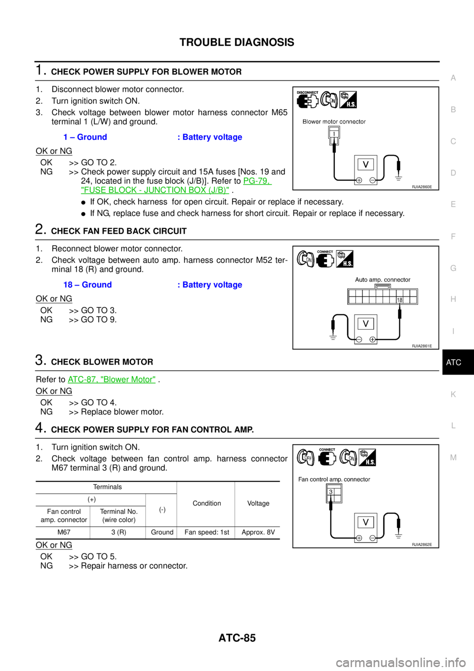
1. CHECK POWER SUPPLY FOR BLOWER MOTOR
1. Disconnect blower motor connector.
2. Turn ignition switch ON.
3. Check voltage between blower motor harness connector M65
terminal 1 (L/W) and ground.
OK or NG
OK >> GO TO 2.
NG >> Check power supply circuit and 15A fuses [Nos. 19 and
24, located in the fuse block (J/B)]. Refer to PG-79,
"FUSE BLOCK - JUNCTION BOX (J/B)" .
�If OK, check harness for open circuit. Repair or replace if necessary.
�If NG, replace fuse and check harness for short circuit. Repair or replace if necessary.
2. CHECK FAN FEED BACK CIRCUIT
1. Reconnect blower motor connector.
2. Check voltage between auto amp. harness connector M52 ter-
minal 18 (R) and ground.
OK or NG
OK >> GO TO 3.
NG >> GO TO 9.
3. CHECK BLOWER MOTOR
Refer to AT C - 8 7 , "
Blower Motor" .
OK or NG
OK >> GO TO 4.
NG >> Replace blower motor.
4. CHECK POWER SUPPLY FOR FAN CONTROL AMP.
1. Turn ignition switch ON.
2. Check voltage between fan control amp. harness connector
M67 terminal 3 (R) and ground.
OK or NG
OK >> GO TO 5.
NG >> Repair harness or connector.1 – Ground : Battery voltage
RJIA2860E
18 – Ground : Battery voltage
RJIA2861E
Terminals
Condition Voltage (+)
(-)
Fan control
amp. connectorTerminal No.
(wire color)
M67 3 (R) Ground Fan speed: 1st Approx. 8V
RJIA2862E
Page 3264 of 4555
ATC-86
TROUBLE DIAGNOSIS
5. CHECK GROUND CIRCUIT FOR FAN CONTROL AMP.
1. Turn ignition switch OFF.
2. Disconnect fan control amp. connector.
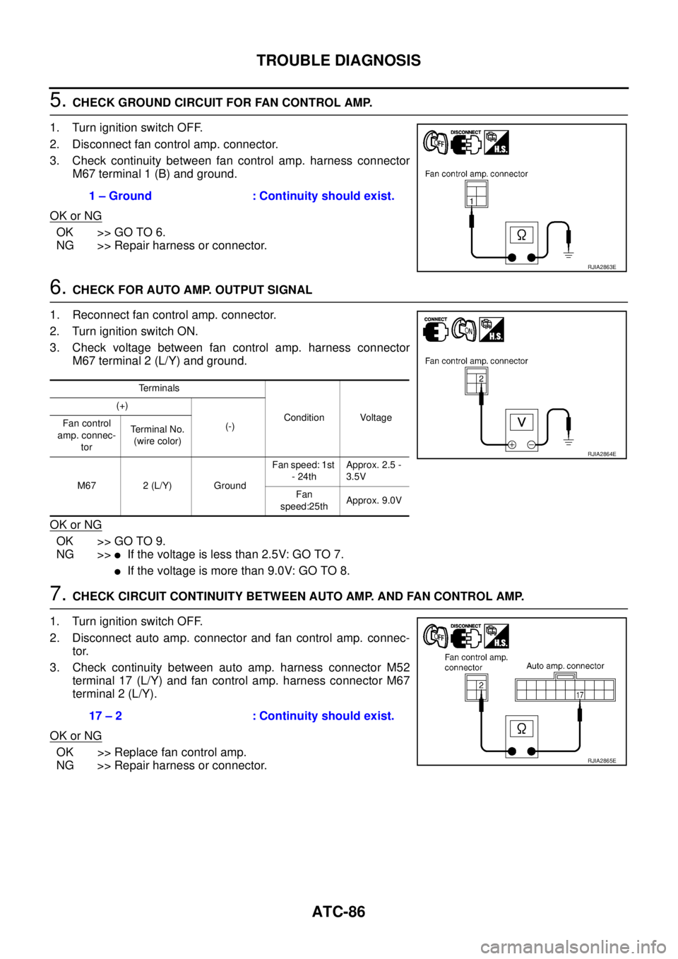
3. Check continuity between fan control amp. harness connector
M67 terminal 1 (B) and ground.
OK or NG
OK >> GO TO 6.
NG >> Repair harness or connector.
6. CHECK FOR AUTO AMP. OUTPUT SIGNAL
1. Reconnect fan control amp. connector.
2. Turn ignition switch ON.
3. Check voltage between fan control amp. harness connector
M67 terminal 2 (L/Y) and ground.
OK or NG
OK >> GO TO 9.
NG >>
�If the voltage is less than 2.5V: GO TO 7.
�If the voltage is more than 9.0V: GO TO 8.
7. CHECK CIRCUIT CONTINUITY BETWEEN AUTO AMP. AND FAN CONTROL AMP.
1. Turn ignition switch OFF.
2. Disconnect auto amp. connector and fan control amp. connec-
tor.
3. Check continuity between auto amp. harness connector M52
terminal 17 (L/Y) and fan control amp. harness connector M67
terminal 2 (L/Y).
OK or NG
OK >> Replace fan control amp.
NG >> Repair harness or connector.1 – Ground : Continuity should exist.
RJIA2863E
Terminals
Condition Voltage (+)
(-) Fan control
amp. connec-
torTerminal No.
(wire color)
M67 2 (L/Y) GroundFan speed: 1st
- 24thApprox. 2.5 -
3.5V
Fan
speed:25thApprox. 9.0V
RJIA2864E
17 – 2 : Continuity should exist.
RJIA2865E
Page 3265 of 4555
TROUBLE DIAGNOSIS
ATC-87
C
D
E
F
G
H
I
K
L
MA
B
AT C
8. CHECK FAN CONTROL AMP.
1. Turn ignition switch OFF.
2. Disconnect fan control amp. connector.
3. Check continuity between fan control amp. connector M67 ter-
minal 2 and 1.
OK or NG
OK >> GO TO 9.
NG >> Replace fan control amp.
9. CHECK CIRCUIT CONTINUITY BETWEEN AUTO AMP. AND FAN CONTROL AMP.
1. Disconnect auto amp. connector.
2. Check continuity between auto amp. harness connector M52
terminal 18 (R) and fan control amp. harness connector M67 ter-
minal 3 (R).
OK or NG
OK >> Replace auto amp.
NG >> Repair harness or connector.
COMPONENT INSPECTION
Blower Motor
Confirm smooth rotation of blower motor.
�Ensure that there are no foreign particles inside intake unit.2 – 1 : Continuity should exist.
SJIA0476E
18 – 3 : Continuity should exist.
RJIA2867E
RJIA0532E
Page 3268 of 4555
ATC-90
TROUBLE DIAGNOSIS
1. CHECK POWER SUPPLY FOR COMPRESSOR
1. Disconnect compressor connector.
2. Start the engine.
3. Turn fan control dial to AUTO position.
4. Press A/C switch.
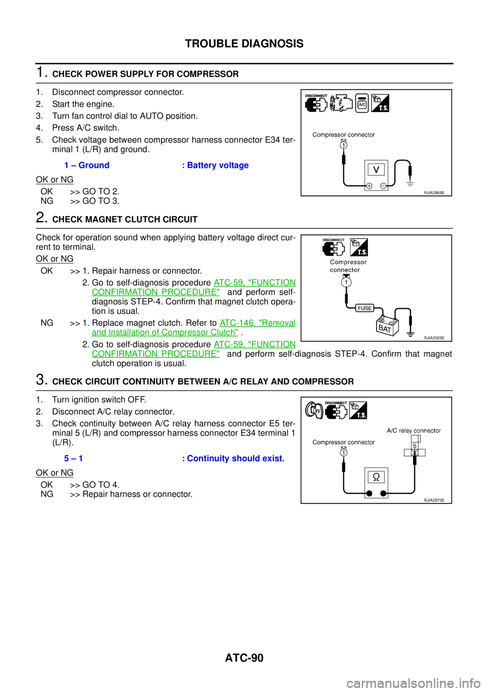
5. Check voltage between compressor harness connector E34 ter-
minal 1 (L/R) and ground.
OK or NG
OK >> GO TO 2.
NG >> GO TO 3.
2. CHECK MAGNET CLUTCH CIRCUIT
Check for operation sound when applying battery voltage direct cur-
rent to terminal.
OK or NG
OK >> 1. Repair harness or connector.
2. Go to self-diagnosis procedure AT C - 5 9 , "
FUNCTION
CONFIRMATION PROCEDURE" and perform self-
diagnosis STEP-4. Confirm that magnet clutch opera-
tion is usual.
NG >> 1. Replace magnet clutch. Refer to ATC-146, "
Removal
and Installation of Compressor Clutch" .
2. Go to self-diagnosis procedure AT C - 5 9 , "
FUNCTION
CONFIRMATION PROCEDURE" and perform self-diagnosis STEP-4. Confirm that magnet
clutch operation is usual.
3. CHECK CIRCUIT CONTINUITY BETWEEN A/C RELAY AND COMPRESSOR
1. Turn ignition switch OFF.
2. Disconnect A/C relay connector.
3. Check continuity between A/C relay harness connector E5 ter-
minal 5 (L/R) and compressor harness connector E34 terminal 1
(L/R).
OK or NG
OK >> GO TO 4.
NG >> Repair harness or connector.1 – Ground : Battery voltage
RJIA2869E
RJIA2005E
5 – 1 : Continuity should exist.
RJIA2870E
Page 3269 of 4555
TROUBLE DIAGNOSIS
ATC-91
C
D
E
F
G
H
I
K
L
MA
B
AT C
4. CHECK POWER SUPPLY FOR A/C RELAY
1. Turn ignition switch ON.
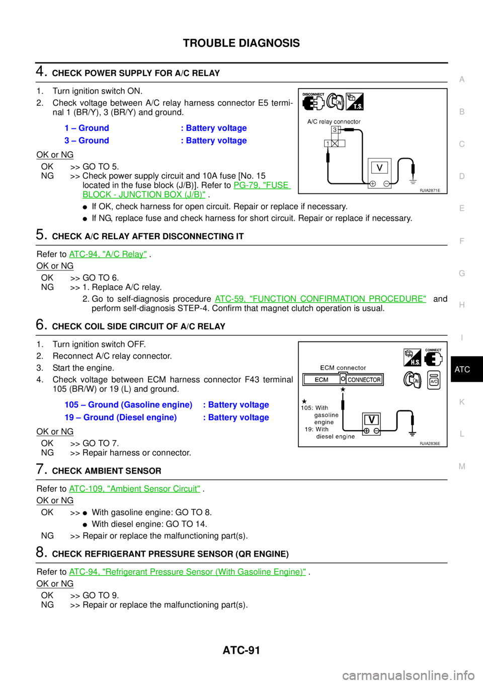
2. Check voltage between A/C relay harness connector E5 termi-
nal 1 (BR/Y), 3 (BR/Y) and ground.
OK or NG
OK >> GO TO 5.
NG >> Check power supply circuit and 10A fuse [No. 15
located in the fuse block (J/B)]. Refer to PG-79, "
FUSE
BLOCK - JUNCTION BOX (J/B)" .
�If OK, check harness for open circuit. Repair or replace if necessary.
�If NG, replace fuse and check harness for short circuit. Repair or replace if necessary.
5. CHECK A/C RELAY AFTER DISCONNECTING IT
Refer to AT C - 9 4 , "
A/C Relay" .
OK or NG
OK >> GO TO 6.
NG >> 1. Replace A/C relay.
2. Go to self-diagnosis procedure AT C - 5 9 , "
FUNCTION CONFIRMATION PROCEDURE" and
perform self-diagnosis STEP-4. Confirm that magnet clutch operation is usual.
6. CHECK COIL SIDE CIRCUIT OF A/C RELAY
1. Turn ignition switch OFF.
2. Reconnect A/C relay connector.
3. Start the engine.
4. Check voltage between ECM harness connector F43 terminal
105 (BR/W) or 19 (L) and ground.
OK or NG
OK >> GO TO 7.
NG >> Repair harness or connector.
7. CHECK AMBIENT SENSOR
Refer to ATC-109, "
Ambient Sensor Circuit" .
OK or NG
OK >>�With gasoline engine: GO TO 8.
�With diesel engine: GO TO 14.
NG >> Repair or replace the malfunctioning part(s).
8. CHECK REFRIGERANT PRESSURE SENSOR (QR ENGINE)
Refer to AT C - 9 4 , "
Refrigerant Pressure Sensor (With Gasoline Engine)" .
OK or NG
OK >> GO TO 9.
NG >> Repair or replace the malfunctioning part(s).1 – Ground : Battery voltage
3 – Ground : Battery voltage
RJIA2871E
105 – Ground (Gasoline engine) : Battery voltage
19 – Ground (Diesel engine) : Battery voltage
RJIA2836E
Page 3270 of 4555
ATC-92
TROUBLE DIAGNOSIS
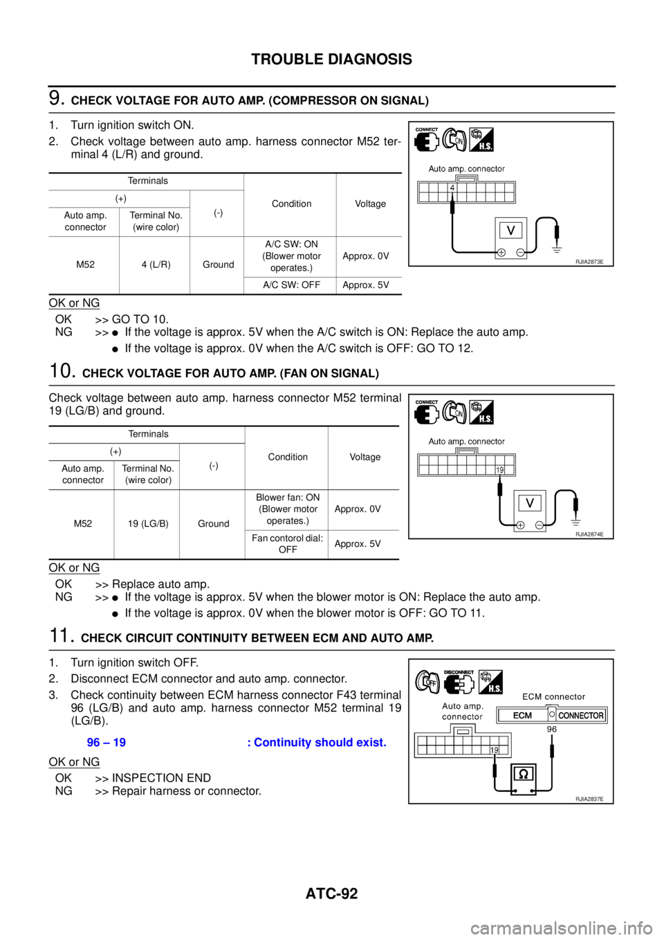
9. CHECK VOLTAGE FOR AUTO AMP. (COMPRESSOR ON SIGNAL)
1. Turn ignition switch ON.
2. Check voltage between auto amp. harness connector M52 ter-
minal 4 (L/R) and ground.
OK or NG
OK >> GO TO 10.
NG >>
�If the voltage is approx. 5V when the A/C switch is ON: Replace the auto amp.
�If the voltage is approx. 0V when the A/C switch is OFF: GO TO 12.
10. CHECK VOLTAGE FOR AUTO AMP. (FAN ON SIGNAL)
Check voltage between auto amp. harness connector M52 terminal
19 (LG/B) and ground.
OK or NG
OK >> Replace auto amp.
NG >>
�If the voltage is approx. 5V when the blower motor is ON: Replace the auto amp.
�If the voltage is approx. 0V when the blower motor is OFF: GO TO 11.
11 . CHECK CIRCUIT CONTINUITY BETWEEN ECM AND AUTO AMP.
1. Turn ignition switch OFF.
2. Disconnect ECM connector and auto amp. connector.
3. Check continuity between ECM harness connector F43 terminal
96 (LG/B) and auto amp. harness connector M52 terminal 19
(LG/B).
OK or NG
OK >> INSPECTION END
NG >> Repair harness or connector.
Te r m i n a l s
Condition Voltage (+)
(-)
Auto amp.
connectorTerminal No.
(wire color)
M52 4 (L/R) GroundA/C SW: ON
(Blower motor
operates.)Approx. 0V
A/C SW: OFF Approx. 5V
RJIA2873E
Terminals
Condition Voltage (+)
(-)
Auto amp.
connectorTerminal No.
(wire color)
M52 19 (LG/B) GroundBlower fan: ON
(Blower motor
operates.)Approx. 0V
Fan contorol dial:
OFFApprox. 5V
RJIA2874E
96 – 19 : Continuity should exist.
RJIA2837E
Page 3271 of 4555
TROUBLE DIAGNOSIS
ATC-93
C
D
E
F
G
H
I
K
L
MA
B
AT C
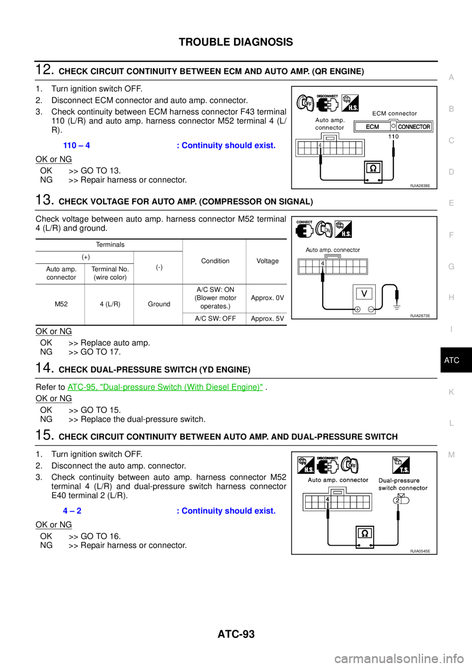
12. CHECK CIRCUIT CONTINUITY BETWEEN ECM AND AUTO AMP. (QR ENGINE)
1. Turn ignition switch OFF.
2. Disconnect ECM connector and auto amp. connector.
3. Check continuity between ECM harness connector F43 terminal
110 (L/R) and auto amp. harness connector M52 terminal 4 (L/
R).
OK or NG
OK >> GO TO 13.
NG >> Repair harness or connector.
13. CHECK VOLTAGE FOR AUTO AMP. (COMPRESSOR ON SIGNAL)
Check voltage between auto amp. harness connector M52 terminal
4 (L/R) and ground.
OK or NG
OK >> Replace auto amp.
NG >> GO TO 17.
14. CHECK DUAL-PRESSURE SWITCH (YD ENGINE)
Refer to AT C - 9 5 , "
Dual-pressure Switch (With Diesel Engine)" .
OK or NG
OK >> GO TO 15.
NG >> Replace the dual-pressure switch.
15. CHECK CIRCUIT CONTINUITY BETWEEN AUTO AMP. AND DUAL-PRESSURE SWITCH
1. Turn ignition switch OFF.
2. Disconnect the auto amp. connector.
3. Check continuity between auto amp. harness connector M52
terminal 4 (L/R) and dual-pressure switch harness connector
E40 terminal 2 (L/R).
OK or NG
OK >> GO TO 16.
NG >> Repair harness or connector.110 – 4 : Continuity should exist.
RJIA2838E
Terminals
Condition Voltage (+)
(-)
Auto amp.
connectorTerminal No.
(wire color)
M52 4 (L/R) GroundA/C SW: ON
(Blower motor
operates.)Approx. 0V
A/C SW: OFF Approx. 5V
RJIA2873E
4 – 2 : Continuity should exist.
RJIA0545E
Page 3287 of 4555
TROUBLE DIAGNOSIS
ATC-109
C
D
E
F
G
H
I
K
L
MA
B
AT C
Ambient Sensor CircuitEJS004YP
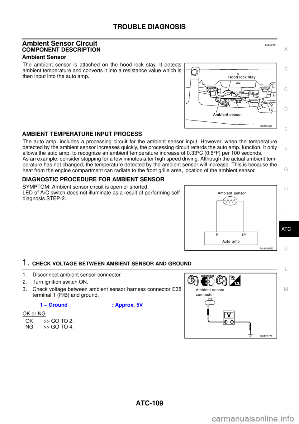
COMPONENT DESCRIPTION
Ambient Sensor
The ambient sensor is attached on the hood lock stay. It detects
ambient temperature and converts it into a resistance value which is
then input into the auto amp.
AMBIENT TEMPERATURE INPUT PROCESS
The auto amp. includes a processing circuit for the ambient sensor input. However, when the temperature
detected by the ambient sensor increases quickly, the processing circuit retards the auto amp. function. It only
allows the auto amp. to recognize an ambient temperature increase of 0.33°C (0.6°F) per 100 seconds.
As an example, consider stopping for a few minutes after high speed driving. Although the actual ambient tem-
perature has not changed, the temperature detected by the ambient sensor will increase. This is because the
heat from the engine compartment can radiate to the front grille area, location of the ambient sensor.
DIAGNOSTIC PROCEDURE FOR AMBIENT SENSOR
SYMPTOM: Ambient sensor circuit is open or shorted.
LED of A/C switch does not illuminate as a result of performing self-
diagnosis STEP-2.
1. CHECK VOLTAGE BETWEEN AMBIENT SENSOR AND GROUND
1. Disconnect ambient sensor connector.
2. Turn ignition switch ON.
3. Check voltage between ambient sensor harness connector E38
terminal 1 (R/B) and ground.
OK or NG
OK >> GO TO 2.
NG >> GO TO 4.
RJIA0048E
RHA051GD
1 – Ground : Approx. 5V
RJIA2017E