Page 1621 of 4555
DTC P0563 BATTERY VOLTAGE
EC-1217
[YD (WITH EURO-OBD)]
C
D
E
F
G
H
I
J
K
L
MA
EC
7. CHECK ELECTRICAL PARTS DAMAGE
Check the following for damage.
�Wiring harness and harness connectors for burn
�Fuses for short
OK or NG
OK >>INSPECTION END
NG >> Repair or replace malfunctioning part.
Page 1960 of 4555
EC-1556
[YD (WITHOUT EURO-OBD)]
DTC P0563 BATTERY VOLTAGE
7. CHECK ELECTRICAL PARTS DAMAGE
Check the following for damage.
�Wiring harness and harness connectors for burn
�Fuses for short
OK or NG
OK >>INSPECTION END
NG >> Repair or replace malfunctioning part.
Page 3246 of 4555
ATC-68
TROUBLE DIAGNOSIS
Potentio Temperature Control (PTC)
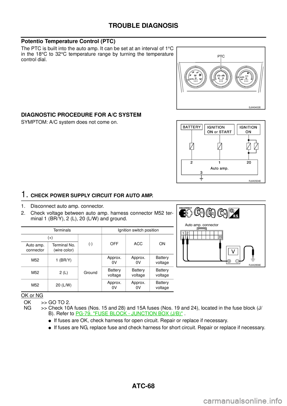
The PTC is built into the auto amp. It can be set at an interval of 1°C
in the 18°C to 32°C temperature range by turning the temperature
control dial.
DIAGNOSTIC PROCEDURE FOR A/C SYSTEM
SYMPTOM: A/C system does not come on.
1. CHECK POWER SUPPLY CIRCUIT FOR AUTO AMP.
1. Disconnect auto amp. connector.
2. Check voltage between auto amp. harness connector M52 ter-
minal 1 (BR/Y), 2 (L), 20 (L/W) and ground.
OK or NG
OK >> GO TO 2.
NG >> Check 10A fuses (Nos. 15 and 28) and 15A fuses (Nos. 19 and 24), located in the fuse block (J/
B). Refer to PG-79, "
FUSE BLOCK - JUNCTION BOX (J/B)" .
�If fuses are OK, check harness for open circuit. Repair or replace if necessary.
�If fuses are NG, replace fuse and check harness for short circuit. Repair or replace if necessary.
SJIA0402E
RJIA0504E
Terminals Ignition switch position
(+)
(-) OFF ACC ON
Auto amp.
connectorTe r m i n a l N o .
(wire color)
M52 1 (BR/Y)
GroundApprox.
0VApprox.
0VBattery
voltage
M52 2 (L)Battery
voltageBattery
voltageBattery
voltage
M52 20 (L/W)Approx.
0VApprox.
0VBattery
voltage
RJIA2856E
Page 3263 of 4555
TROUBLE DIAGNOSIS
ATC-85
C
D
E
F
G
H
I
K
L
MA
B
AT C
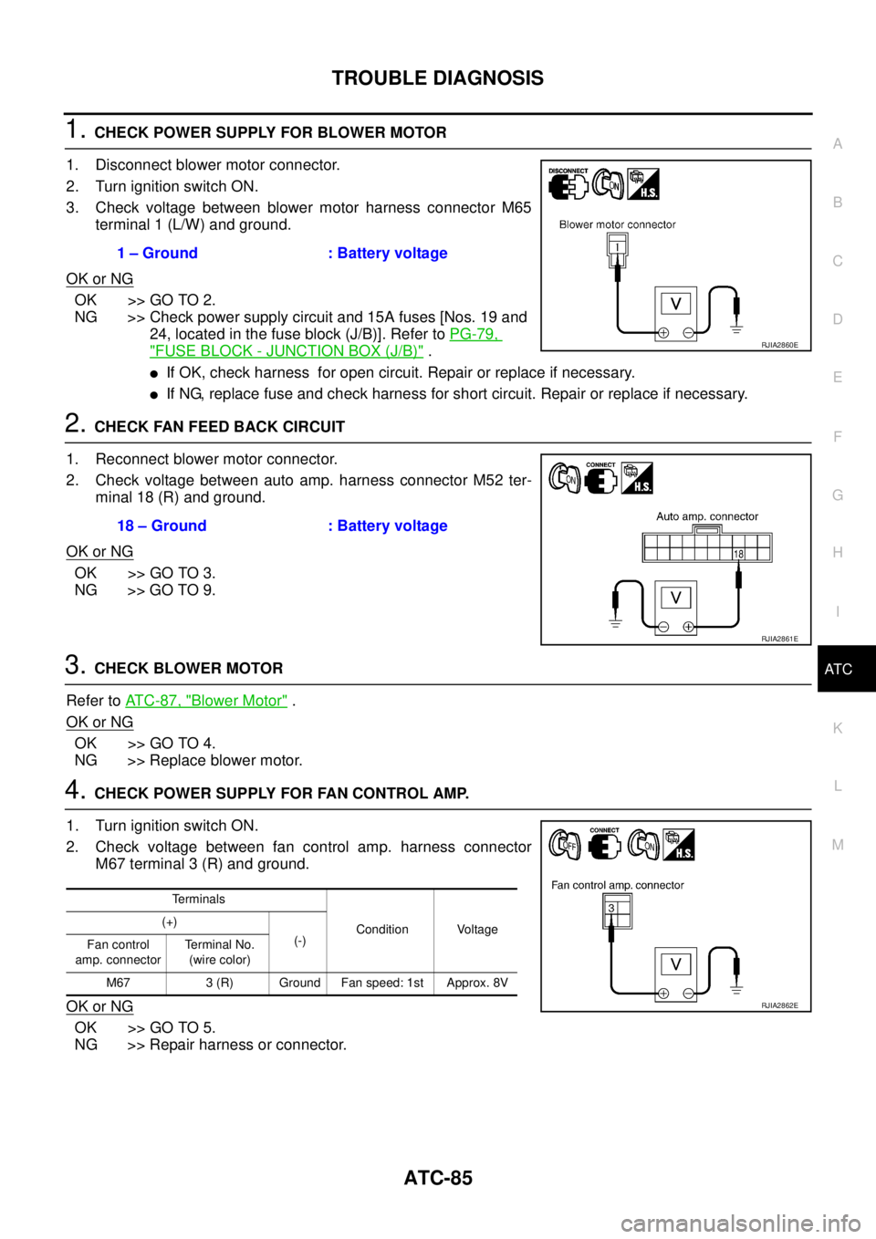
1. CHECK POWER SUPPLY FOR BLOWER MOTOR
1. Disconnect blower motor connector.
2. Turn ignition switch ON.
3. Check voltage between blower motor harness connector M65
terminal 1 (L/W) and ground.
OK or NG
OK >> GO TO 2.
NG >> Check power supply circuit and 15A fuses [Nos. 19 and
24, located in the fuse block (J/B)]. Refer to PG-79,
"FUSE BLOCK - JUNCTION BOX (J/B)" .
�If OK, check harness for open circuit. Repair or replace if necessary.
�If NG, replace fuse and check harness for short circuit. Repair or replace if necessary.
2. CHECK FAN FEED BACK CIRCUIT
1. Reconnect blower motor connector.
2. Check voltage between auto amp. harness connector M52 ter-
minal 18 (R) and ground.
OK or NG
OK >> GO TO 3.
NG >> GO TO 9.
3. CHECK BLOWER MOTOR
Refer to AT C - 8 7 , "
Blower Motor" .
OK or NG
OK >> GO TO 4.
NG >> Replace blower motor.
4. CHECK POWER SUPPLY FOR FAN CONTROL AMP.
1. Turn ignition switch ON.
2. Check voltage between fan control amp. harness connector
M67 terminal 3 (R) and ground.
OK or NG
OK >> GO TO 5.
NG >> Repair harness or connector.1 – Ground : Battery voltage
RJIA2860E
18 – Ground : Battery voltage
RJIA2861E
Terminals
Condition Voltage (+)
(-)
Fan control
amp. connectorTerminal No.
(wire color)
M67 3 (R) Ground Fan speed: 1st Approx. 8V
RJIA2862E
Page 3422 of 4555
AV-80
NAVIGATION SYSTEM
Power Supply and Ground Circuit Check for NAVI Control UnitEKS00F35
1. CHECK FUSE
Check that the following fuses of the NAVI control unit are not blown.
OK or NG
OK >> GO TO 2.
NG >> If fuse is blown, be sure to eliminate cause of problem before installing new fuse. Refer to PG-2,
"POWER SUPPLY ROUTING" .
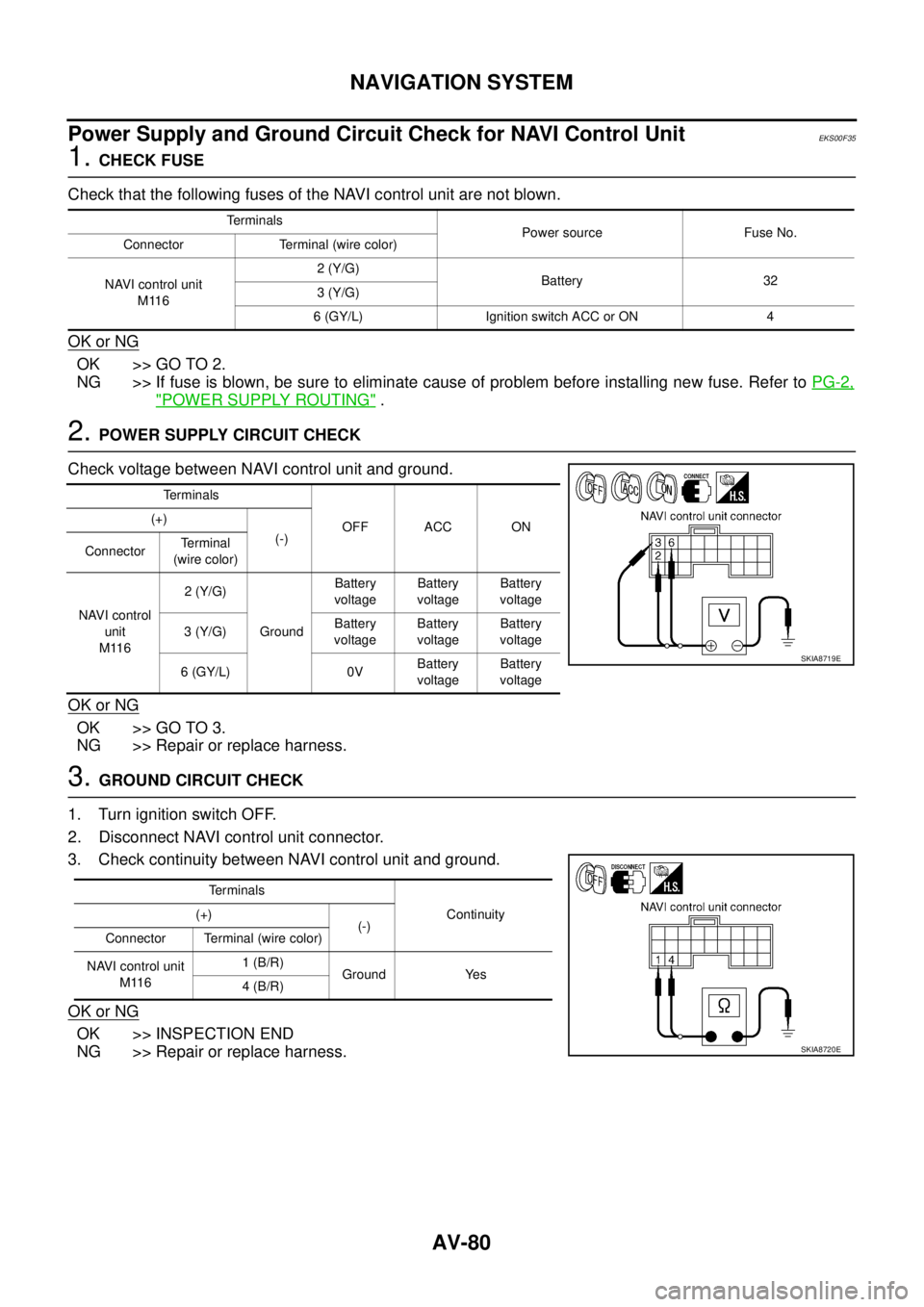
2. POWER SUPPLY CIRCUIT CHECK
Check voltage between NAVI control unit and ground.
OK or NG
OK >> GO TO 3.
NG >> Repair or replace harness.
3. GROUND CIRCUIT CHECK
1. Turn ignition switch OFF.
2. Disconnect NAVI control unit connector.
3. Check continuity between NAVI control unit and ground.
OK or NG
OK >> INSPECTION END
NG >> Repair or replace harness.
Te r m i n a l s
Power source Fuse No.
Connector Terminal (wire color)
NAVI control unit
M1162 (Y/G)
Battery 32
3 (Y/G)
6 (GY/L) Ignition switch ACC or ON 4
Terminals
OFF ACC ON (+)
(-)
ConnectorTerminal
(wire color)
NAVI control
unit
M1162 (Y/G)
GroundBattery
voltageBattery
voltageBattery
voltage
3 (Y/G)Battery
voltageBattery
voltageBattery
voltage
6 (GY/L) 0VBattery
voltageBattery
voltage
SKIA8719E
Te r m i n a l s
Continuity (+)
(-)
Connector Terminal (wire color)
NAVI control unit
M1161 (B/R)
Ground Yes
4 (B/R)
SKIA8720E
Page 3423 of 4555

NAVIGATION SYSTEM
AV-81
C
D
E
F
G
H
I
J
L
MA
B
AV
Power Supply and Ground Circuit Check for DisplayEKS00F36
1. CHECK FUSE
Check that the following fuses of the display are not blown.
OK or NG
OK >> GO TO 2.
NG >> If fuse is blown, be sure to eliminate cause of problem before installing new fuse. Refer to PG-2,
"POWER SUPPLY ROUTING" .
2. POWER SUPPLY CIRCUIT CHECK
Check voltage between display and ground.
OK or NG
OK >> GO TO 3.
NG >> Repair or replace harness.
3. GROUND CIRCUIT CHECK
1. Turn ignition switch OFF.
2. Disconnect display connector.
3. Check continuity between display and ground.
OK or NG
OK >> INSPECTION END
NG >> Repair or replace harness.
UnitTerminals
Power source Fuse No.
Connector Terminal (wire color)
Display M11221 (Y/G)
Battery 32
23 (Y/G)
19 (GY/L) Ignition switch ACC or ON 4
UnitTerminals
OFF ACC ON (+)
(-)
ConnectorTerminal
(wire color)
Display M11221 (Y/G)
GroundBattery
voltageBattery
voltageBattery
voltage
23 (Y/G)Battery
voltageBattery
voltageBattery
voltage
19 (GY/L) 0VBattery
voltageBattery
voltage
SKIA9491E
UnitTe r m i n a l s
Continuity (+)
(-)
Connector Terminal (wire color)
Display M11222 (B/R)
Ground Yes
24 (B/R)
SKIA9492E
Page 3425 of 4555
NAVIGATION SYSTEM
AV-83
C
D
E
F
G
H
I
J
L
MA
B
AV
Power Supply and Ground Circuit Check for Transfer UnitEKS00F38
1. CHECK FUSE
Check that the following fuses of the transfer unit are not blown.
OK or NG
OK >> GO TO 2.
NG >> If fuse is blown, be sure to eliminate cause of problem before installing new fuse. Refer to PG-2,
"POWER SUPPLY ROUTING" .
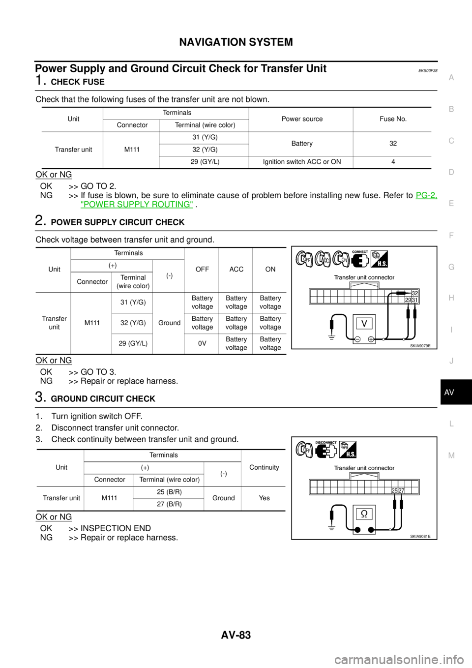
2. POWER SUPPLY CIRCUIT CHECK
Check voltage between transfer unit and ground.
OK or NG
OK >> GO TO 3.
NG >> Repair or replace harness.
3. GROUND CIRCUIT CHECK
1. Turn ignition switch OFF.
2. Disconnect transfer unit connector.
3. Check continuity between transfer unit and ground.
OK or NG
OK >> INSPECTION END
NG >> Repair or replace harness.
UnitTerminals
Power source Fuse No.
Connector Terminal (wire color)
Transfer unit M11131 (Y/G)
Battery 32
32 (Y/G)
29 (GY/L) Ignition switch ACC or ON 4
UnitTerminals
OFF ACC ON (+)
(-)
ConnectorTerminal
(wire color)
Transfer
unitM 11131 (Y/G)
GroundBattery
voltageBattery
voltageBattery
voltage
32 (Y/G)Battery
voltageBattery
voltageBattery
voltage
29 (GY/L) 0VBattery
voltageBattery
voltage
SKIA9079E
UnitTerminals
Continuity (+)
(-)
Connector Terminal (wire color)
Transfer unit M11125 (B/R)
Ground Yes
27 (B/R)
SKIA9081E
Page 3426 of 4555
AV-84
NAVIGATION SYSTEM
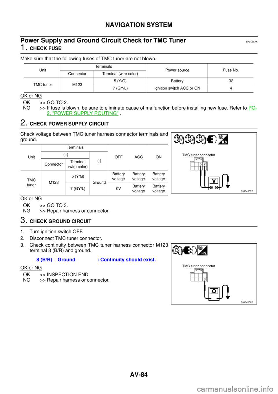
Power Supply and Ground Circuit Check for TMC TunerEKS00LYK
1. CHECK FUSE
Make sure that the following fuses of TMC tuner are not blown.
OK or NG
OK >> GO TO 2.
NG >> If fuse is blown, be sure to eliminate cause of malfunction before installing new fuse. Refer to PG-
2, "POWER SUPPLY ROUTING" .
2. CHECK POWER SUPPLY CIRCUIT
Check voltage between TMC tuner harness connector terminals and
ground.
OK or NG
OK >> GO TO 3.
NG >> Repair harness or connector.
3. CHECK GROUND CIRCUIT
1. Turn ignition switch OFF.
2. Disconnect TMC tuner connector.
3. Check continuity between TMC tuner harness connector M123
terminal 8 (B/R) and ground.
OK or NG
OK >> INSPECTION END
NG >> Repair harness or connector.
UnitTerminals
Power source Fuse No.
Connector Terminal (wire color)
TMC tuner M1235 (Y/G) Battery 32
7 (GY/L) Ignition switch ACC or ON 4
UnitTerminals
OFF ACC ON (+)
(-)
ConnectorTe r m i n a l
(wire color)
TMC
tunerM1235 (Y/G)
GroundBattery
voltageBattery
voltageBattery
voltage
7 (GY/L) 0VBattery
voltageBattery
voltage
SKIB4007E
8 (B/R) – Ground : Continuity should exist.
SKIB4008E