Page 3940 of 4555

MTC-16
TROUBLE DIAGNOSIS
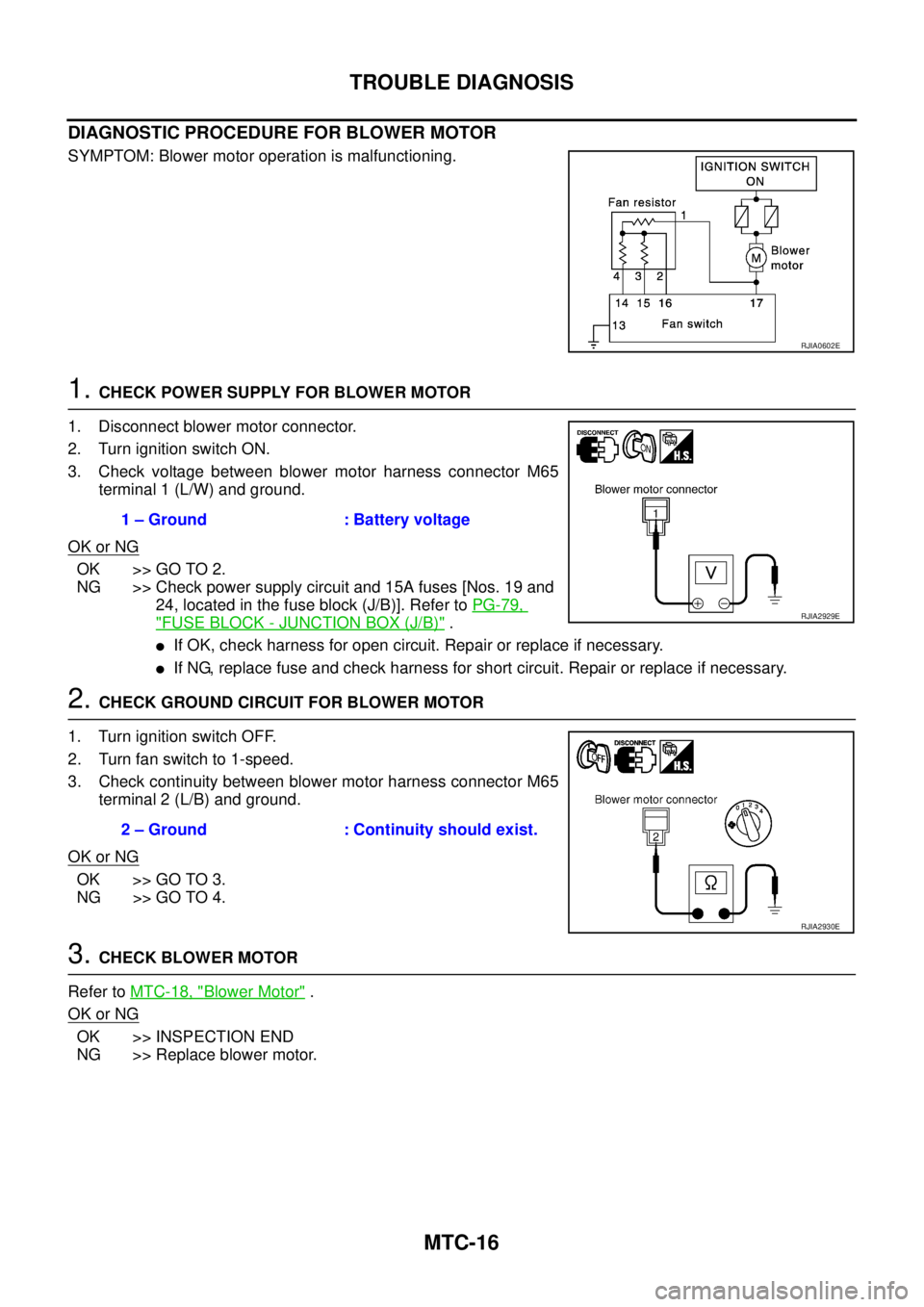
DIAGNOSTIC PROCEDURE FOR BLOWER MOTOR
SYMPTOM: Blower motor operation is malfunctioning.
1. CHECK POWER SUPPLY FOR BLOWER MOTOR
1. Disconnect blower motor connector.
2. Turn ignition switch ON.
3. Check voltage between blower motor harness connector M65
terminal 1 (L/W) and ground.
OK or NG
OK >> GO TO 2.
NG >> Check power supply circuit and 15A fuses [Nos. 19 and
24, located in the fuse block (J/B)]. Refer to PG-79,
"FUSE BLOCK - JUNCTION BOX (J/B)" .
�If OK, check harness for open circuit. Repair or replace if necessary.
�If NG, replace fuse and check harness for short circuit. Repair or replace if necessary.
2. CHECK GROUND CIRCUIT FOR BLOWER MOTOR
1. Turn ignition switch OFF.
2. Turn fan switch to 1-speed.
3. Check continuity between blower motor harness connector M65
terminal 2 (L/B) and ground.
OK or NG
OK >> GO TO 3.
NG >> GO TO 4.
3. CHECK BLOWER MOTOR
Refer to MTC-18, "
Blower Motor" .
OK or NG
OK >> INSPECTION END
NG >> Replace blower motor.
RJIA0602E
1 – Ground : Battery voltage
RJIA2929E
2 – Ground : Continuity should exist.
RJIA2930E
Page 4171 of 4555

COMBINATION METERS
DI-23
C
D
E
F
G
H
I
J
L
MA
B
DI
4. CHECK LOW-FUEL WARNING LAMP ILLUMINATION
During fuel warning lamp check, confirm illumination of low-fuel warning lamp.
OK or NG
OK >> GO TO 5.
NG >> Replace combination meter.
5. CHECK METER CIRCUIT
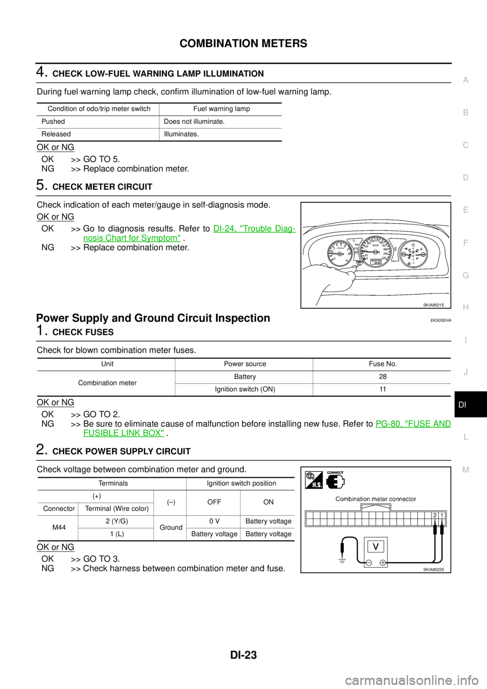
Check indication of each meter/gauge in self-diagnosis mode.
OK or NG
OK >> Go to diagnosis results. Refer to DI-24, "Trouble Diag-
nosis Chart for Symptom" .
NG >> Replace combination meter.
Power Supply and Ground Circuit InspectionEKS00EHA
1. CHECK FUSES
Check for blown combination meter fuses.
OK or NG
OK >> GO TO 2.
NG >> Be sure to eliminate cause of malfunction before installing new fuse. Refer to PG-80, "
FUSE AND
FUSIBLE LINK BOX" .
2. CHECK POWER SUPPLY CIRCUIT
Check voltage between combination meter and ground.
OK or NG
OK >> GO TO 3.
NG >> Check harness between combination meter and fuse.
Condition of odo/trip meter switch Fuel warning lamp
Pushed Does not illuminate.
Released Illuminates.
SKIA8921E
Unit Power source Fuse No.
Combination meterBattery 28
Ignition switch (ON) 11
Terminals Ignition switch position
(+)
(–) OFF ON
Connector Terminal (Wire color)
M442 (Y/G)
Ground0 V Battery voltage
1 (L) Battery voltage Battery voltage
SKIA8922E
Page 4208 of 4555

DI-60
WARNING CHIME
Symptom ChartEKS002XQ
Power Supply and Ground Circuit InspectionEKS002YF
1. CHECK FUSES
Check for blown time control unit fuses.
OK or NG
OK >> GO TO 2.
NG >> Be sure to eliminate cause of malfunction before installing new fuse. Refer to PG-79, "
FUSE
BLOCK - JUNCTION BOX (J/B)" .
2. CHECK POWER SUPPLY CIRCUIT
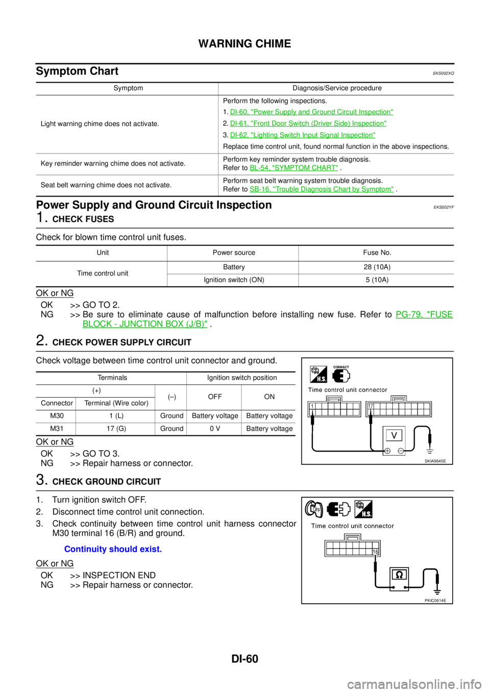
Check voltage between time control unit connector and ground.
OK or NG
OK >> GO TO 3.
NG >> Repair harness or connector.
3. CHECK GROUND CIRCUIT
1. Turn ignition switch OFF.
2. Disconnect time control unit connection.
3. Check continuity between time control unit harness connector
M30 terminal 16 (B/R) and ground.
OK or NG
OK >> INSPECTION END
NG >> Repair harness or connector.
Symptom Diagnosis/Service procedure
Light warning chime does not activate.Perform the following inspections.
1.DI-60, "
Power Supply and Ground Circuit Inspection"
2.DI-61, "Front Door Switch (Driver Side) Inspection"
3.DI-62, "Lighting Switch Input Signal Inspection"
Replace time control unit, found normal function in the above inspections.
Key reminder warning chime does not activate. Perform key reminder system trouble diagnosis.
Refer to BL-54, "
SYMPTOM CHART" .
Seat belt warning chime does not activate.Perform seat belt warning system trouble diagnosis.
Refer to SB-16, "
Trouble Diagnosis Chart by Symptom" .
Unit Power source Fuse No.
Time control unitBattery 28 (10A)
Ignition switch (ON) 5 (10A)
Terminals Ignition switch position
(+)
(–) OFF ON
Connector Terminal (Wire color)
M30 1 (L) Ground Battery voltage Battery voltage
M31 17 (G) Ground 0 V Battery voltage
SKIA9645E
Continuity should exist.
PKIC0614E