Page 360 of 3171

ATC-26
AIR CONDITIONER CONTROL
AIR CONDITIONER CONTROL
PFP:27500
DescriptionEJS006B0
The front air control provides automatic regulation of the vehicle's interior temperature. The system is based
on the driver's and passenger's selected “set temperature”, regardless of the outside temperature changes.
This is done by utilizing a microcomputer, also referred to as the front air control, which receives input signals
from the following six sensors:
lAmbient sensor
lIn-vehicle sensor
lIntake sensor
lOptical sensor (one sensor for driver and passenger side)
lPBR (Position Balanced Resistor).
lVehicle speed sensor
The front air control uses these signals (including the set temperature) to automatically control:
lOutlet air volume
lAir temperature
lAir distribution
The front air control is used to select:
lOutlet air volume
lAir temperature/distribution
OperationEJS006B1
AIR MIX DOORS CONTROL
The air mix doors are automatically controlled so that in-vehicle temperature is maintained at a predetermined
value by the temperature setting, ambient temperature, in-vehicle temperature and amount of sunload.
BLOWER SPEED CONTROL
Blower speed is automatically controlled by the temperature setting, ambient temperature, in-vehicle tempera-
ture, intake temperature, amount of sunload and air mix door position.
When AUTO switch is pressed, the blower motor starts to gradually increase air flow volume (if required).
When engine coolant temperature is low, the blower motor operation is delayed to prevent cool air from flow-
ing.
INTAKE DOOR CONTROL
The intake door is automatically controlled by the temperature setting, ambient temperature, in-vehicle tem-
perature, intake temperature, amount of sunload and the ON-OFF operation of the compressor.
MODE DOOR CONTROL
The mode door is automatically controlled by the temperature setting, ambient temperature, in-vehicle temper-
ature, intake temperature and amount of sunload.
DEFROSTER DOOR CONTROL
The defroster door is controlled by: Turning the defroster dial to front defroster.
Page 415 of 3171

TROUBLE DIAGNOSIS
ATC-81
C
D
E
F
G
H
I
K
L
MA
B
AT C
SYSTEM DESCRIPTION
Component Parts
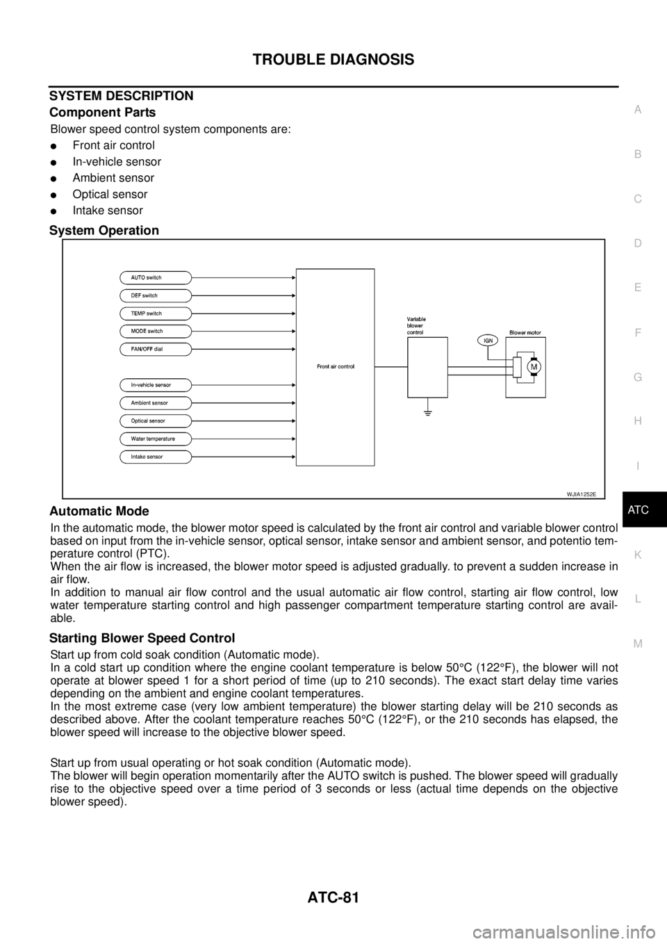
Blower speed control system components are:
lFront air control
lIn-vehicle sensor
lAmbient sensor
lOptical sensor
lIntake sensor
System Operation
Automatic Mode
In the automatic mode, the blower motor speed is calculated by the front air control and variable blower control
based on input from the in-vehicle sensor, optical sensor, intake sensor and ambient sensor, and potentio tem-
perature control (PTC).
When the air flow is increased, the blower motor speed is adjusted gradually. to prevent a sudden increase in
air flow.
In addition to manual air flow control and the usual automatic air flow control, starting air flow control, low
water temperature starting control and high passenger compartment temperature starting control are avail-
able.
Starting Blower Speed Control
Start up from cold soak condition (Automatic mode).
In a cold start up condition where the engine coolant temperature is below 50°C(122°F), the blower will not
operate at blower speed 1 for a short period of time (up to 210 seconds). The exact start delay time varies
depending on the ambient and engine coolant temperatures.
In the most extreme case (very low ambient temperature) the blower starting delay will be 210 seconds as
described above. After the coolant temperature reaches 50°C(122°F), or the 210 seconds has elapsed, the
blower speed will increase to the objective blower speed.
Start up from usual operating or hot soak condition (Automatic mode).
The blower will begin operation momentarily after the AUTO switch is pushed. The blower speed will gradually
rise to the objective speed over a time period of 3 seconds or less (actual time depends on the objective
blower speed).
WJIA1252E
Page 434 of 3171
ATC-100
TROUBLE DIAGNOSIS
Insufficient Heating
EJS006BS
SYMPTOM: Insufficient heating
INSPECTION FLOW
*1ATC-57, "Operational Check".*2AT C - 6 8 , "Air Mix Door Motor Circuit".*3ATC-55, "A/C System Self-diagno-
sis Function".
*4ATC-55, "
A/C System Self-diagnosis
Function".*5AT C - 8 0 , "
Blower Motor Circuit".*6EC-103, "DTC P0117, P0118 ECT
SENSOR".
*7CO-7, "
Changing Engine Coolant".*8CO-13, "Checking Reservoir Tank
Cap".
MJIB0350E
Page 458 of 3171
ATC-124
HEATER & COOLING UNIT ASSEMBLY
HEATER & COOLING UNIT ASSEMBLY
PFP:27110
ComponentsEJS006C8
Heater and Cooling Unit Assembly —LHD Models—
MJIB0278E
1. High-pressure A/C pipe 2. Low-pressure A/C pipe 3. Expansion valve
4. Heater core and evaporator pipes
grommet5. A/C drain hose grommet 6. A/C drain hose
7. Heater core pipes 8. Coolant reservoir hose 9. Heater and cooling unit assembly
Page 460 of 3171

ATC-126
HEATER & COOLING UNIT ASSEMBLY
Removal and Installation
EJS006C9
REMOVAL
1. Discharge the refrigerant from the A/C system. Refer toATC-138, "Discharging Refrigerant".
2. Drain the coolant from the engine cooling system. Refer toCO-8, "
DRAINING ENGINE COOLANT".
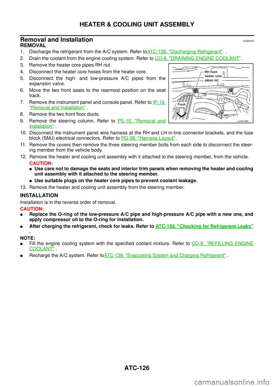
3. Remove the heater core pipes RH nut.
4. Disconnect the heater core hoses from the heater core.
5. Disconnect the high- and low-pressure A/C pipes from the
expansion valve.
6. Move the two front seats to the rearmost position on the seat
track.
7. Remove the instrument panel and console panel. Refer toIP-10,
"Removal and Installation".
8. Remove the two front floor ducts.
9. Remove the steering column. Refer toPS-10, "
Removal and
Installation".
10. Disconnect the instrument panel wire harness at the RH and LH in-line connector brackets, and the fuse
block (SMJ) electrical connectors. Refer toPG-38, "
Harness Layout".
11. Remove the covers then remove the three steering member bolts from each side to disconnect the steer-
ing member from the vehicle body.
12. Remove the heater and cooling unit assembly with it attached to the steering member, from the vehicle.
CAUTION:
lUse care not to damage the seats and interior trim panels when removing the heater and cooling
unit assembly with it attached to the steering member.
lUse suitable plugs on the heater core pipes to prevent coolant leakage.
13. Remove the heater and cooling unit assembly from the steering member.
INSTALLATION
Installation is in the reverse order of removal.
CAUTION:
lReplace the O-ring of the low-pressure A/C pipe and high-pressure A/C pipe with a new one, and
apply compressor oil to the O-ring for installation.
lAfter charging the refrigerant, check for leaks. Refer toATC-150, "Checking for Refrigerant Leaks"
.
NOTE:
lFill the engine cooling system with the specified coolant mixture. Refer toCO-8, "REFILLING ENGINE
COOLANT".
lRecharge the A/C system. Refer toATC-138, "Evacuating System and Charging Refrigerant".
LJIA0165E
Page 461 of 3171
HEATER CORE
ATC-127
C
D
E
F
G
H
I
K
L
MA
B
AT C
HEATER COREPFP:27140
ComponentsEJS006CA
Removal and InstallationEJS006CB
REMOVAL
1. Remove the heater and cooling unit assembly. Refer toATC-126, "REMOVAL".
2. Remove the three screws and remove the heater core cover.
3. Remove the heater core and evaporator pipe bracket.
4. Remove the heater core.
NOTE:
If the air conditioner filters are contaminated from coolant leak-
ing from the heater core, replace the air conditioner filters with
new ones before installing the new heater core.
INSTALLATION
Installation is in the reverse order of removal.
1. Heater core and evaporator pipe bracket 2. Heater core 3. Heater and cooling unit assembly
4. Heater core cover
MJIB0211E
MJIB0216E
Page 462 of 3171
ATC-128
HEATER PUMP
HEATER PUMP
PFP:92264
ComponentsEJS006CC
Heater Pump
Removal and InstallationEJS006DC
REMOVAL
1. Partially drain the engine cooling system. Refer toCO-8, "DRAINING ENGINE COOLANT".
2. Disconnect the heater pump electrical connector.
3. Disconnect the two heater hoses.
4. Remove the heater pump from the bracket securing the heater pump to the cowl top.
CAUTION:
Do not disassemble the heater pump, replace the heater pump as an assembly.
INSTALLATION
Installation is in the reverse order of removal.
CAUTION:
lThe heater pump rubber mount must be fully seated on the bracket.
lDo not disassemble the heater pump, replace the heater pump as an assembly.
LBIA0414E
1. Cowl top 2. Heater pump electrical connector 3. Heater pump
4. Heater hose 5. Heater hose
Page 802 of 3171

BR-16
LOAD SENSING VALVE
Inspection
EFS006A8
INSPECTION
1. With the vehicle in unladen condition, a person should sit in driver's seat at the rear. Then he/she should
get out of car gently. (This is to stabilize suspension deflection.)
NOTE:
“Unladen condition”: with full coolant, lubricant, 6 to 8 litters of fuel, spare tyre, jack, and hand tools
loaded.
2. Press load sensing valve against stopper bolt. Check if center-to-center length “L” between adjusting ref-
erence hole and reference pin is as specified below.
lIf measurement is outside the standard, perform following;
loosen mounting bolt of sensor spring bracket. By moving
sensor spring bracket, adjust so that the length “L” comes into
specified range.
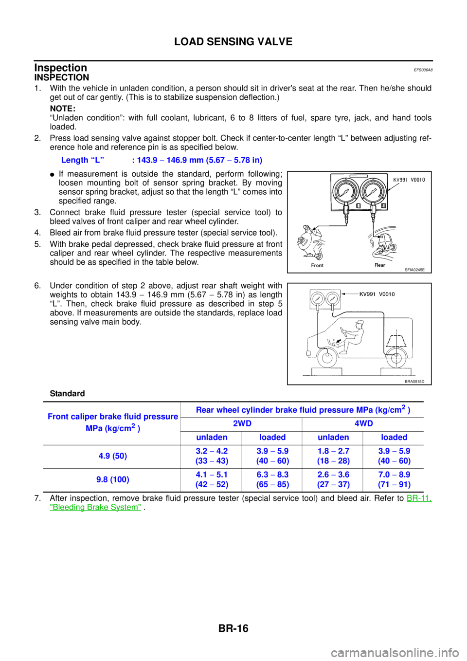
3. Connect brake fluid pressure tester (special service tool) to
bleed valves of front caliper and rear wheel cylinder.
4. Bleed air from brake fluid pressure tester (special service tool).
5. With brake pedal depressed, check brake fluid pressure at front
caliper and rear wheel cylinder. The respective measurements
should be as specified in the table below.
6. Under condition of step 2 above, adjust rear shaft weight with
weights to obtain 143.9-146.9 mm (5.67-5.78 in) as length
“L”. Then, check brake fluid pressure as described in step 5
above. If measurements are outside the standards, replace load
sensing valve main body.
Standard
7. After inspection, remove brake fluid pressure tester (special service tool) and bleed air. Refer toBR-11,
"Bleeding Brake System". Length “L” : 143.9-146.9 mm (5.67-5.78 in)
SFIA0245E
BRA0515D
Front caliper brake fluid pressure
MPa (kg/cm
2)Rear wheel cylinder brake fluid pressure MPa (kg/cm
2)
2WD 4WD
unladen loaded unladen loaded
4.9 (50)3.2-4.2
(33-43)3.9-5.9
(40-60)1.8-2.7
(18-28)3.9-5.9
(40-60)
9.8 (100)4.1-5.1
(42-52)6.3-8.3
(65-85)2.6-3.6
(27-37)7.0-8.9
(71-91)