2005 NISSAN NAVARA ignition
[x] Cancel search: ignitionPage 3066 of 3171
TROUBLE DIAGNOSIS FOR SYMPTOMS
TF-99
C
E
F
G
H
I
J
K
L
MA
B
TF
5.CHECK TRANSFER CONTROL UNIT
Check transfer control unit input/output signal. Refer toTF-38, "
Transfer Control Unit Input/Output Signal Ref-
erence Values".
OK or NG
OK >> GO TO 6.
NG >> Check transfer control unit pin terminals for damage or loose connection with harness connector.
If any items are damaged, repair or replace damaged parts.
6.CHECK TRANSFER INNER PARTS
1. Disassemble transfer assembly. Refer toTF-112, "
Disassembly and Assembly".
2. Check transfer inner parts.
OK or NG
OK >>INSPECTION END
NG >> Repair or replace damaged parts.
4WD Warning Lamp Flashes SlowlyEDS0032I
SYMPTOM:
While driving, 4WD warning lamp flashes slowly. (Continues to flash until turning ignition switch OFF.)
NOTE:
Slow flashing: 1 time/2 seconds
DIAGNOSTIC PROCEDURE
1.CHECK TIRES
Check the following.
lTire pressure
lWear condition
lLongitudinal tire size (There is no difference between longitudinal tires.)
OK or NG
OK >> GO TO 2.
NG >> Repair or replace damaged parts.
2.CHECK SYMPTOM
Check again.
OK or NG
OK >>INSPECTION END
NG >> GO TO 3.
3.CHECK TRANSFER CONTROL UNIT
Check transfer control unit input/output signal. Refer toTF-38, "
Transfer Control Unit Input/Output Signal Ref-
erence Values".
OK or NG
OK >>INSPECTION END
NG >> Check transfer control unit pin terminals for damage or loose connection with harness connector.
If any items are damaged, repair or replace damaged parts.
Page 3067 of 3171
TF-100
TRANSFER CONTROL UNIT
TRANSFER CONTROL UNIT
PFP:33084
Removal and InstallationEDS0032J
REMOVAL
1. Switch 4WD shift switch to 2WD and set transfer assembly to 2WD.
CAUTION:
When removal transfer control unit, transfer state must be at 2WD or AUTO.
2. Turn the ignition switch OFF and disconnect the battery cables.
3. Remove the lower instrument panel LH (LHD models) or lower instrument panel RH (RHD models). Refer
toIP-13, "
LOWER INSTRUMENT PANEL LH"(LHD models) orIP-13, "LOWER INSTRUMENT PANEL
LH"(RHD models).
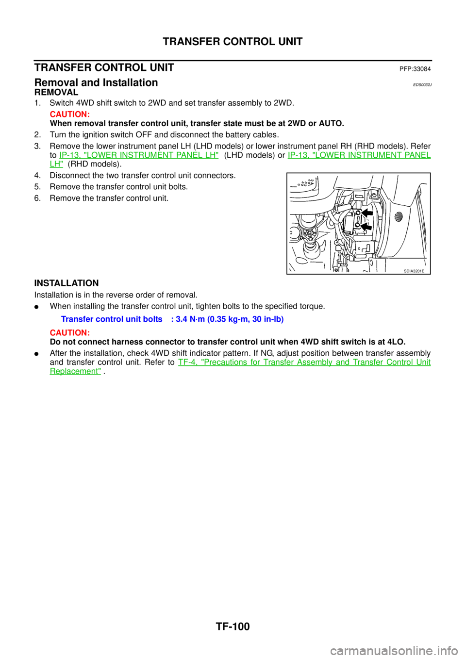
4. Disconnect the two transfer control unit connectors.
5. Remove the transfer control unit bolts.
6. Remove the transfer control unit.
INSTALLATION
Installation is in the reverse order of removal.
lWhen installing the transfer control unit, tighten bolts to the specified torque.
CAUTION:
Do not connect harness connector to transfer control unit when 4WD shift switch is at 4LO.
lAfter the installation, check 4WD shift indicator pattern. If NG, adjust position between transfer assembly
and transfer control unit. Refer toTF-4, "
Precautions for Transfer Assembly and Transfer Control Unit
Replacement".
SDIA3201E
Transfer control unit bolts : 3.4 N·m (0.35 kg-m, 30 in-lb)
Page 3115 of 3171
WW-4
FRONT WIPER AND WASHER SYSTEM
FRONT WIPER AND WASHER SYSTEM
PFP:28810
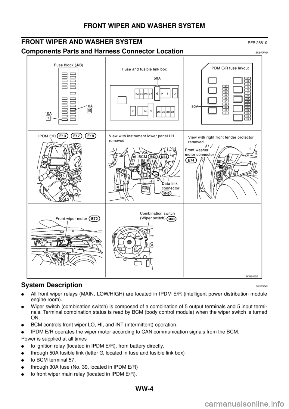
Components Parts and Harness Connector LocationEKS00P4U
System DescriptionEKS00P4V
lAll front wiper relays (MAIN, LOW/HIGH) are located in IPDM E/R (intelligent power distribution module
engine room).
lWiper switch (combination switch) is composed of a combination of 5 output terminals and 5 input termi-
nals. Terminal combination status is read by BCM (body control module) when the wiper switch is turned
ON.
lBCM controls front wiper LO, HI, and INT (intermittent) operation.
lIPDM E/R operates the wiper motor according to CAN communication signals from the BCM.
Power is supplied at all times
lto ignition relay (located in IPDM E/R), from battery directly,
lthrough 50A fusible link (letter G, located in fuse and fusible link box)
lto BCM terminal 57,
lthrough 30A fuse (No. 39, located in IPDM E/R)
lto front wiper main relay (located in IPDM E/R).
SKIB6805E
Page 3116 of 3171
![NISSAN NAVARA 2005 Repair Workshop Manual FRONT WIPER AND WASHER SYSTEM
WW-5
C
D
E
F
G
H
I
J
L
MA
B
WW
With the ignition switch in ON or START position, power is supplied
lthrough 10A fuse [No. 15, located in fuse block (J/B)]
lto combination NISSAN NAVARA 2005 Repair Workshop Manual FRONT WIPER AND WASHER SYSTEM
WW-5
C
D
E
F
G
H
I
J
L
MA
B
WW
With the ignition switch in ON or START position, power is supplied
lthrough 10A fuse [No. 15, located in fuse block (J/B)]
lto combination](/manual-img/5/57362/w960_57362-3115.png)
FRONT WIPER AND WASHER SYSTEM
WW-5
C
D
E
F
G
H
I
J
L
MA
B
WW
With the ignition switch in ON or START position, power is supplied
lthrough 10A fuse [No. 15, located in fuse block (J/B)]
lto combination switch terminal 2,
lthrough 10A fuse [No. 1, located in fuse block (J/B)]
lto BCM terminal 3.
Ground is supplied
lto BCM terminal 55 and
lto combination switch terminal 9
lthrough grounds M21, M80 and M83,
lto IPDM E/R terminals 38 and 59 and
lto front wiper motor terminal 2
lthrough grounds E21, E41 and E61.
LOW SPEED WIPER OPERATION
When the ignition switch is in the ON or START position, and the front wiper switch is turned to the low posi-
tion, the BCM detects a low speed wiper ON request through the combination switch (wiper switch) reading
function.
The BCM then sends a front wiper (low) request signal with CAN communication.
lfrom BCM terminals 21 and 22
lto IPDM E/R terminals 39 and 40.
When IPDM E/R receives front wiper (low) request signal, it supplies ground to energize the front wiper main
relay.
With the front wiper LOW/ HIGH relay energized, power is supplied
lthrough front wiper main relay
lthrough front wiper LOW/HIGH relay
lthrough IPDM E/R terminal 32
lto front wiper motor terminal 1.
Ground is supplied
lto front wiper motor terminal 2
lthrough grounds E21, E41 and E61.
With power and ground supplied, the front wiper motor operates at low speed.
HI SPEED WIPER OPERATION
When the ignition switch is in the ON or START position, and the front wiper switch is turned to the high posi-
tion, the BCM detects a high speed wiper ON request through the combination switch (wiper switch) reading
function.
The BCM then sends a front wiper (high) request signal with CAN communication.
lfrom BCM terminals 21 and 22
lto IPDM E/R terminals 39 and 40.
When IPDM E/R receives front wiper (high) request signal, it supplies ground to energize the front wiper main
relays.
With the front wiper LOW/HIGH relays energized, power is supplied
lthrough front wiper main relay
lthrough front wiper LOW/HIGH relay
lthrough IPDM E/R terminal 35
lto front wiper motor terminal 4.
Ground is supplied
lto front wiper motor terminal 2
lthrough grounds E21, E41 and E61.
With power and ground supplied, the front wiper motor operates at high speed.
Page 3117 of 3171

WW-6
FRONT WIPER AND WASHER SYSTEM
INTERMITTENT OPERATION
When front wiper switch is turned to INT position, wiper performs intermittent operation, low-speed operation,
and high-speed operation according to water drop increase rate on windshield detected by light and rain sen-
sor. If light and rain sensor malfunctions, it operates as vehicle speed sensing wiper during driving and oper-
ates intermittent operation according to INT-volume switch with vehicle stopped. During this time, BCM
controls each operation.
The BCM then sends a front wiper (HI or LOW) request signal with CAN communication.
lfrom BCM terminals 21 and 22
lto IPDM E/R terminals 39 and 40.
When the BCM determines that combination switch status is front wiper intermittent ON, it performs the follow-
ing operations.
lBCM detects intermittent wiper dial position.
lBCM sends front wiper request signal (HI or LOW) to IPDM E/R at calculated operation interval.
When IPDM E/R receives front wiper request signal (HI or LOW), it supplies ground to energize the front wiper
main relay and front wiper LOW/HIGH relay. It then sends an auto-stop signal to the BCM, and conducts inter-
mittent front wiper motor operation.
AUTO STOP OPERATION
When the wiper arms are not located at the base of the windshield, and the wiper switch is turned OFF, the
wiper motor will continue to operate until the wiper arms reach the windshield base. When the wiper arms
reach the base of windshield, front wiper motor terminals 2 and 5 are connected.
Ground is supplied
lto IPDM E/R terminal 43
lthrough front wiper motor terminal 5
lthrough front wiper motor terminal 2
lthrough grounds E21, E41 and E61.
The IPDM E/R sends an auto stop operation signal to the BCM with CAN communication.
When the BCM receives an auto stop operation signal, the BCM sends wiper stop signal to the IPDM E/R over
CAN communication lines. The IPDM E/R then de-energizes the front wiper main relay.
The wiper motor will then stop the wiper arms at the STOP position.
FRONT WASHER OPERATION
When the ignition switch is in the ON or START position, and the front washer switches are OFF, the front
washer motor is supplied power
lthrough 10A fuse [No. 15, located in fuse block (J/B)]
lthrough combination switch (wiper switch) terminal 2
lthrough combination switch (wiper switch) terminal 4
lto front washer motor terminal 1.
When the front wiper switch is in the front washer position, the BCM detects a front washer signal request
through the combination switch (wiper switch) reading function.
Combination switch ground is supplied
lto front washer motor terminal 2
lthrough combination switch (wiper switch) terminal 3
lthrough combination switch (wiper switch) terminal 9
lthrough grounds M21, M80 and M83.
With ground supplied, the front washer motor is operated in the front direction.
When the BCM detects that front washer motor has operated for 0.4 seconds or longer, the BCM uses CAN
communication and sends a wiper request signal to the IPDM E/R for low speed operation of wipers.
When the BCM detects that the washer switch is OFF, low speed operation cycles approximately 3 times and
then stops.
Page 3118 of 3171
FRONT WIPER AND WASHER SYSTEM
WW-7
C
D
E
F
G
H
I
J
L
MA
B
WW
MIST OPERATION
When the wiper switch is temporarily placed in the mist position, wiper low speed operation cycles once and
then stops.
For additional information about wiper operation under this condition, refer toWW-5, "
LOW SPEED WIPER
OPERATION".
If the switch is held in the mist position, low speed operation continues.
FAIL-SAFE FUNCTION
The BCM includes fail-safe function to prevent malfunction of electrical components controlled by CAN com-
munications if a malfunction in CAN communications occurs.
The BCM uses CAN communications to stop output of electrical components it controls.
Until the ignition switch is turned OFF, the front wiper system remains in same status as just before fail-safe
control was initiated. (If wiper was in low speed operation just before fail-safe, it continues low speed operation
until ignition switch is turned OFF.)
When fail-safe status is initiated, the BCM remains in standby until normal signals are received.
When normal signals are received, fail-safe status is canceled.
Page 3126 of 3171
FRONT WIPER AND WASHER SYSTEM
WW-15
C
D
E
F
G
H
I
J
L
MA
B
WW
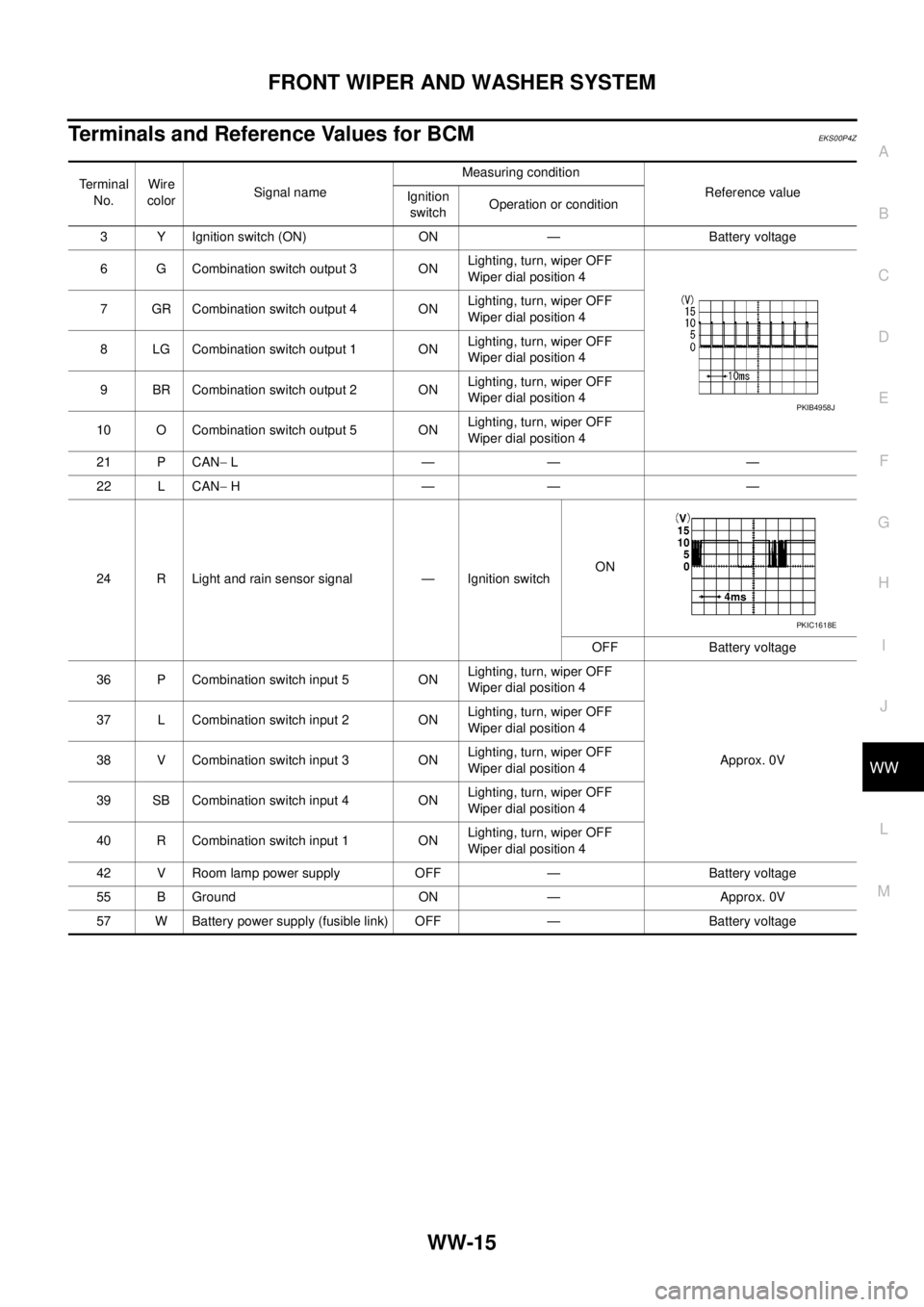
Terminals and Reference Values for BCMEKS00P4Z
Te r m i n a l
No.Wire
colorSignal nameMeasuring condition
Reference value
Ignition
switchOperation or condition
3 Y Ignition switch (ON) ON — Battery voltage
6 G Combination switch output 3 ONLighting, turn, wiper OFF
Wiper dial position 4
7 GR Combination switch output 4 ONLighting, turn, wiper OFF
Wiper dial position 4
8 LG Combination switch output 1 ONLighting, turn, wiper OFF
Wiper dial position 4
9 BR Combination switch output 2 ONLighting, turn, wiper OFF
Wiper dial position 4
10 O Combination switch output 5 ONLighting, turn, wiper OFF
Wiper dial position 4
21 P CAN-L—— —
22 L CAN-H—— —
24 R Light and rain sensor signal — Ignition switchON
OFF Battery voltage
36 P Combination switch input 5 ONLighting, turn, wiper OFF
Wiper dial position 4
Approx. 0V 37 L Combination switch input 2 ONLighting, turn, wiper OFF
Wiper dial position 4
38 V Combination switch input 3 ONLighting, turn, wiper OFF
Wiper dial position 4
39 SB Combination switch input 4 ONLighting, turn, wiper OFF
Wiper dial position 4
40 R Combination switch input 1 ONLighting, turn, wiper OFF
Wiper dial position 4
42 V Room lamp power supply OFF — Battery voltage
55 B Ground ON — Approx. 0V
57 W Battery power supply (fusible link) OFF — Battery voltage
PKIB4958J
PKIC1618E
Page 3127 of 3171
WW-16
FRONT WIPER AND WASHER SYSTEM
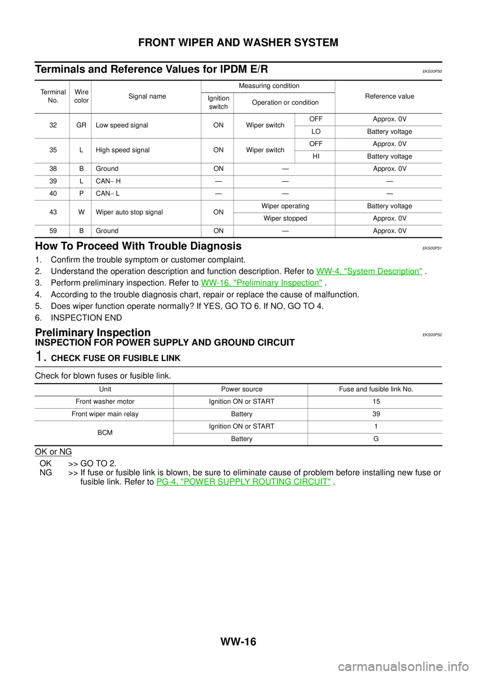
Terminals and Reference Values for IPDM E/R
EKS00P50
How To Proceed With Trouble DiagnosisEKS00P51
1. Confirm the trouble symptom or customer complaint.
2. Understand the operation description and function description. Refer toWW-4, "
System Description".
3. Perform preliminary inspection. Refer toWW-16, "
Preliminary Inspection".
4. According to the trouble diagnosis chart, repair or replace the cause of malfunction.
5. Does wiper function operate normally? If YES, GO TO 6. If NO, GO TO 4.
6. INSPECTION END
Preliminary InspectionEKS00P52
INSPECTION FOR POWER SUPPLY AND GROUND CIRCUIT
1.CHECK FUSE OR FUSIBLE LINK
Check for blown fuses or fusible link.
OK or NG
OK >> GO TO 2.
NG >> If fuse or fusible link is blown, be sure to eliminate cause of problem before installing new fuse or
fusible link. Refer toPG-4, "
POWER SUPPLY ROUTING CIRCUIT".
Te r m i n a l
No.Wire
colorSignal nameMeasuring condition
Reference value
Ignition
switchOperation or condition
32 GR Low speed signal ON Wiper switchOFF Approx. 0V
LO Battery voltage
35 L High speed signal ON Wiper switchOFF Approx. 0V
HI Battery voltage
38 B Ground ON — Approx. 0V
39 L CAN-H—— —
40 P CAN-L—— —
43 W Wiper auto stop signal ONWiper operating Battery voltage
Wiper stopped Approx. 0V
59 B Ground ON — Approx. 0V
Unit Power source Fuse and fusible link No.
Front washer motor Ignition ON or START 15
Front wiper main relay Battery 39
BCMIgnition ON or START 1
Battery G