2005 NISSAN NAVARA ignition
[x] Cancel search: ignitionPage 2144 of 3171

AUTO LIGHT SYSTEM
LT-61
C
D
E
F
G
H
I
J
L
MA
B
LT
Display Item List
NOTE:
This item is displayed, but cannot be monitored.
ACTIVE TEST
Operation Procedure
1. Touch “HEAD LAMP” on “SELECT TEST ITEM” screen.
2. Touch “ACTIVE TEST” on “SELECT DIAG MODE” screen.
3. Touch item to be tested and check operation of the selected item.
4. During the operation check, touching “OFF” deactivates the operation.
Display Item List
Monitor item Contents
IGN ON SW “ON/OFF”Displays status (ignition switch IGN position: ON/other: OFF) of ignition switch judged from
the ignition switch signal.
ACC ON SW “ON/OFF”Displays status (ignition switch ACC or IGN position: ON/other: OFF) of ignition switch judged
from the ignition switch signal.
HI BEAM SW “ON/OFF”Displays status (lighting switch high beam position: ON/other: OFF) of high beam switch
judged from the lighting switch signal.
HEAD LAMP SW 1 “ON/OFF”Displays status (lighting switch 2ND position: ON/other: OFF) of headlamp 1 switch judged
from the lighting switch signal.
HEAD LAMP SW 2 “ON/OFF”Displays status (lighting switch 2ND position: ON/other: OFF) of headlamp 2 switch judged
from the lighting switch signal.
LIGHT SW 1ST “ON/OFF”Displays status (lighting switch 1ST or 2ND position: ON/other: OFF) of lighting switch 1ST
position switch judged from the lighting switch signal.
PASSING SW “ON/OFF”Displays status (lighting switch passing position: ON/other: OFF) of passing switch judged
from the lighting switch signal.
FR FOG SW “ON/OFF”Displays status (lighting switch front fog lamp ON position: ON/others: OFF) of front fog lamp
switch judged from the lighting switch signal.
RR FOG SW “ON/OFF”Displays status (lighting switch rear fog lamp ON position: ON/others: OFF) of rear fog lamp
switch judged from the lighting switch signal.
DOOR SW - DR “ON/OFF”Displays status (door is open: ON/door is closed: OFF) of driver side door switch judged from
the driver side door switch signal.
DOOR SW - AS “ON/OFF”Displays status (door is open: ON/door is closed: OFF) of passenger side door switch judged
from the passenger side door switch signal.
DOOR SW - RR “ON/OFF”Displays status (door is open: ON/door is closed: OFF) of rear door switch (RH) judged from
the rear door switch (RH) signal.
DOOR SW - RL “ON/OFF”Displays status (door is open: ON/door is closed: OFF) of rear door switch (LH) judged from
the rear door switch (LH) signal.
BACK DOOR SW “ON/OFF”Displays status (door is open: ON/door is closed: OFF) of back door switch judged from the
back door switch signal.
TURN SIGNAL R “ON/OFF”Displays status (turn signal switch right position: ON/other: OFF) of turn RH switch judged
from the turn signal switch signal.
TURN SIGNAL L “ON/OFF”Displays status (turn signal switch left position: ON/other: OFF) of turn LH switch judged from
the turn signal switch signal.
CARGO LAMP SW
NOTE“OFF” —
HD LIGHT TIMER“10 sec/
30 sec”Displays status (MODE 1: 10 sec./ MODE 2: 30 sec.) of head light timer.
LIT-SEN FAIL
NOTE“OK” —
AUT LIGHT SYS
NOTE“OFF” —
Test item Description
TAIL LAMP Allows tail lamp relay to operate by switching ON-OFF.
HEAD LAMP Allows headlamp relay (HI, LO) to operate by switching ON-OFF.
Page 2146 of 3171
AUTO LIGHT SYSTEM
LT-63
C
D
E
F
G
H
I
J
L
MA
B
LT
Light and Rain Sensor System InspectionEKS00Q88
1.CHECK LIGHT AND RAIN SENSOR INPUT SIGNAL
1. Turn ignition switch OFF.
2. Disconnect BCM connector.
3. Turn ignition switch ON.
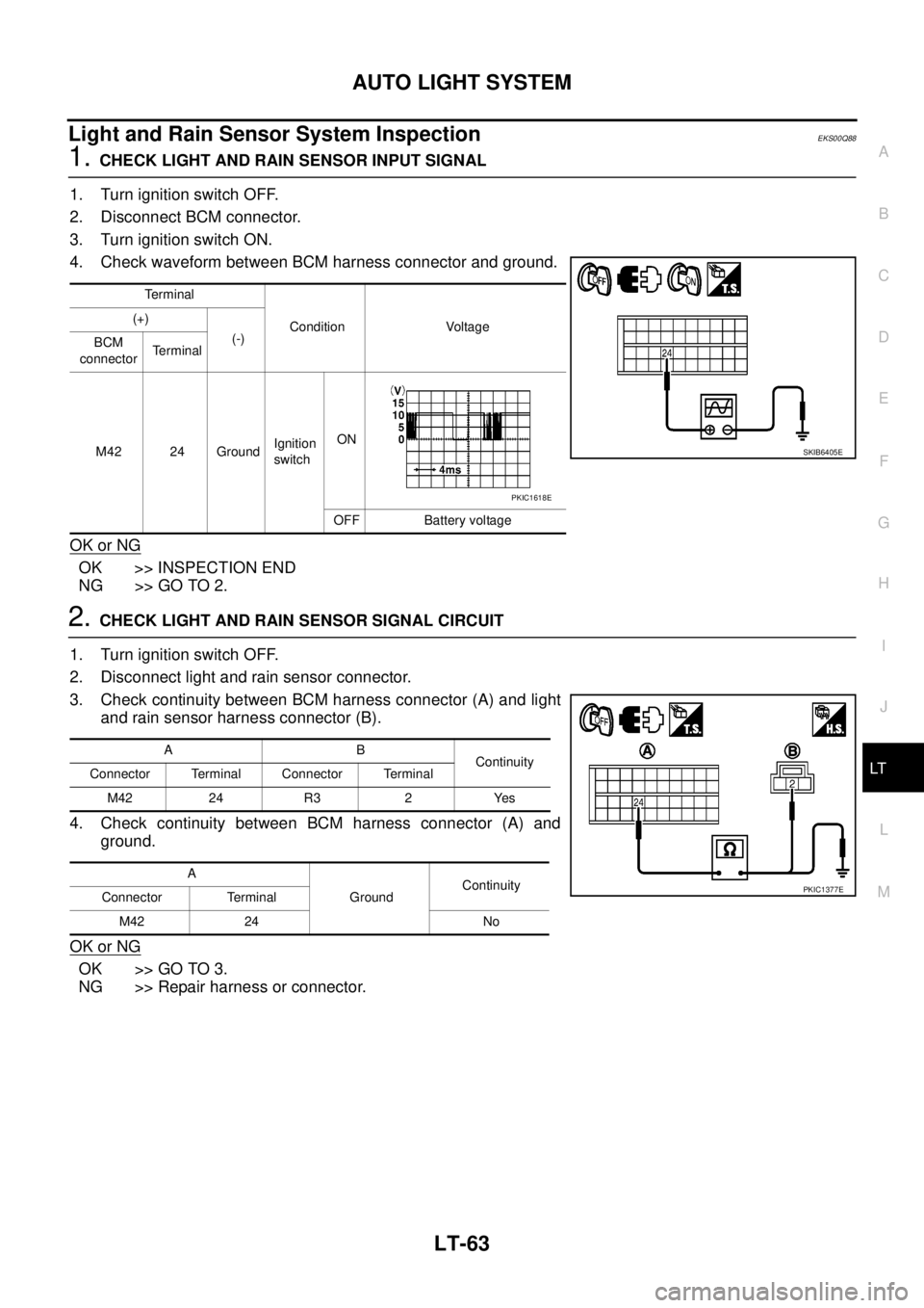
4. Check waveform between BCM harness connector and ground.
OK or NG
OK >> INSPECTION END
NG >> GO TO 2.
2.CHECK LIGHT AND RAIN SENSOR SIGNAL CIRCUIT
1. Turn ignition switch OFF.
2. Disconnect light and rain sensor connector.
3. Check continuity between BCM harness connector (A) and light
and rain sensor harness connector (B).
4. Check continuity between BCM harness connector (A) and
ground.
OK or NG
OK >> GO TO 3.
NG >> Repair harness or connector.
Terminal
Condition Voltage (+)
(-)
BCM
connectorTerminal
M42 24 GroundIgnition
switchON
OFF Battery voltage
SKIB6405E
PKIC1618E
AB
Continuity
Connector Terminal Connector Terminal
M42 24 R3 2 Yes
A
GroundContinuity
Connector Terminal
M42 24 No
PKIC1377E
Page 2147 of 3171
LT-64
AUTO LIGHT SYSTEM
3.CHECK LIGHT AND RAIN SENSOR SIGNAL GROUND CIRCUIT
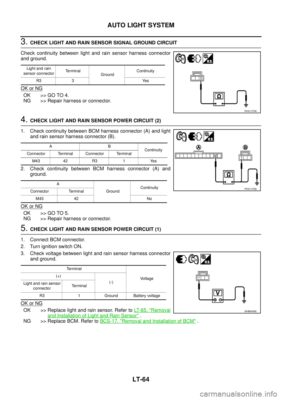
Check continuity between light and rain sensor harness connector
and ground.
OK or NG
OK >> GO TO 4.
NG >> Repair harness or connector.
4.CHECK LIGHT AND RAIN SENSOR POWER CIRCUIT (2)
1. Check continuity between BCM harness connector (A) and light
and rain sensor harness connector (B).
2. Check continuity between BCM harness connector (A) and
ground.
OK or NG
OK >> GO TO 5.
NG >> Repair harness or connector.
5.CHECK LIGHT AND RAIN SENSOR POWER CIRCUIT (1)
1. Connect BCM connector.
2. Turn ignition switch ON.
3. Check voltage between light and rain sensor harness connector
and ground.
OK or NG
OK >> Replace light and rain sensor. Refer toLT-65, "Removal
and Installation of Light and Rain Sensor".
NG >> Replace BCM. Refer toBCS-17, "
Removal and Installation of BCM".
Light and rain
sensor connectorTerminal
GroundContinuity
R3 3 Yes
PKIC1375E
AB
Continuity
Connector Terminal Connector Terminal
M43 42 R3 1 Yes
A
GroundContinuity
Connector Terminal
M43 42 No
PKIC1376E
Terminal
Voltage (+)
(-)
Light and rain sensor
connectorTe r m i n a l
R3 1 Ground Battery voltage
SKIB6406E
Page 2154 of 3171
FRONT FOG LAMP
LT-71
C
D
E
F
G
H
I
J
L
MA
B
LT
FRONT FOG LAMPPFP:26150
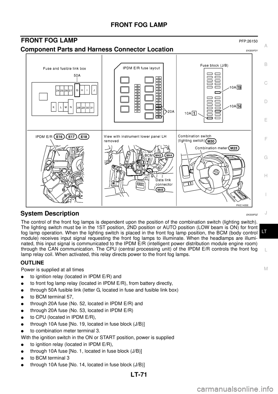
Component Parts and Harness Connector LocationEKS00P3Y
System DescriptionEKS00P3Z
The control of the front fog lamps is dependent upon the position of the combination switch (lighting switch).
The lighting switch must be in the 1ST position, 2ND position or AUTO position (LOW beam is ON) for front
fog lamp operation. When the lighting switch is placed in the front fog lamp position, the BCM (body control
module) receives input signal requesting the front fog lamps to illuminate. When the headlamps are illumi-
nated, this input signal is communicated to the IPDM E/R (intelligent power distribution module engine room)
through the CAN communication. The CPU (central processing unit) of the IPDM E/R controls the front fog
lamp relay coil. When activated, this relay directs power to the front fog lamps.
OUTLINE
Power is supplied at all times
lto ignition relay (located in IPDM E/R) and
lto front fog lamp relay (located in IPDM E/R), from battery directly,
lthrough 50A fusible link (letter G, located in fuse and fusible link box)
lto BCM terminal 57,
lthrough 20A fuse (No. 52, located in IPDM E/R) and
lthrough 20A fuse (No. 53, located in IPDM E/R)
lto CPU (located in IPDM E/R),
lthrough 10A fuse [No. 19, located in fuse block (J/B)]
lto combination meter terminal 3.
With the ignition switch in the ON or START position, power is supplied
lto ignition relay (located in IPDM E/R),
lthrough 10A fuse [No. 1, located in fuse block (J/B)]
lto BCM terminal 3
lthrough 10A fuse [No. 14, located in fuse block (J/B)]
PKIC1405E
Page 2160 of 3171
FRONT FOG LAMP
LT-77
C
D
E
F
G
H
I
J
L
MA
B
LT
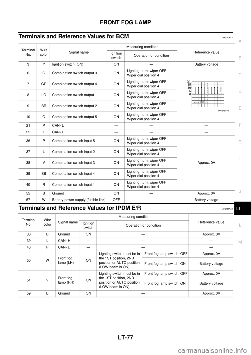
Terminals and Reference Values for BCMEKS00P43
Terminals and Reference Values for IPDM E/REKS00P44
Te r m i n a l
No.Wire
colorSignal nameMeasuring condition
Reference value
Ignition
switchOperation or condition
3 Y Ignition switch (ON) ON — Battery voltage
6 G Combination switch output 3 ONLighting, turn, wiper OFF
Wiper dial position 4
7 GR Combination switch output 4 ONLighting, turn, wiper OFF
Wiper dial position 4
8 LG Combination switch output 1 ONLighting, turn, wiper OFF
Wiper dial position 4
9 BR Combination switch output 2 ONLighting, turn, wiper OFF
Wiper dial position 4
10 O Combination switch output 5 ONLighting, turn, wiper OFF
Wiper dial position 4
21 P CAN- L — — —
22 L CAN- H — — —
36 P Combination switch input 5 ONLighting, turn, wiper OFF
Wiper dial position 4
Approx. 0V 37 L Combination switch input 2 ONLighting, turn, wiper OFF
Wiper dial position 4
38 V Combination switch input 3 ONLighting, turn, wiper OFF
Wiper dial position 4
39 SB Combination switch input 4 ONLighting, turn, wiper OFF
Wiper dial position 4
40 R Combination switch input 1 ONLighting, turn, wiper OFF
Wiper dial position 4
55 B Ground ON — Approx. 0V
57 W Battery power supply (fusible link) OFF — Battery voltage
PKIB4958J
Terminal
No.Wire
colorSignal nameMeasuring condition
Reference value
Ignition
switchOperation or condition
38 B Ground ON — Approx. 0V
39 L CAN- H — — —
40 P CAN- L — — —
50 WFront fog
lamp (LH)ONLighting switch must be in
the 1ST position, 2ND
position or AUTO position
(LOW beam is ON)Front fog lamp switch: OFF Approx. 0V
Front fog lamp switch: ON Battery voltage
51 VFront fog
lamp (RH)ONLighting switch must be in
the 1ST position, 2ND
position or AUTO position
(LOW beam is ON)Front fog lamp switch: OFF Approx. 0V
Front fog lamp switch: ON Battery voltage
59 B Ground ON — Approx. 0V
Page 2161 of 3171
LT-78
FRONT FOG LAMP
How to Proceed With Trouble Diagnosis
EKS00P45
1. Confirm the symptom or customer complaint.
2. Understand operation description and function description. Refer toLT-71, "
System Description".
3. Perform the Preliminary Check. Refer toLT-78, "
Preliminary Check".
4. Check symptom and repair or replace the cause of malfunction.
5. Does the front fog lamp operate normally? If YES: GO TO 6. If NO: GO TO 4.
6. INSPECTION END
Preliminary CheckEKS00P46
CHECK POWER SUPPLY AND GROUND CIRCUIT
1.CHECK FUSES OR FUSIBLE LINK
Check for blown fuses or fusible link.
Refer toLT-74, "Wiring Diagram—F/FOG—".
OK or NG
OK >> GO TO 2.
NG >> If fuse or fusible link is blown, be sure to eliminate cause of malfunction before installing new fuse
or fusible link. Refer toPG-4, "
POWER SUPPLY ROUTING CIRCUIT".
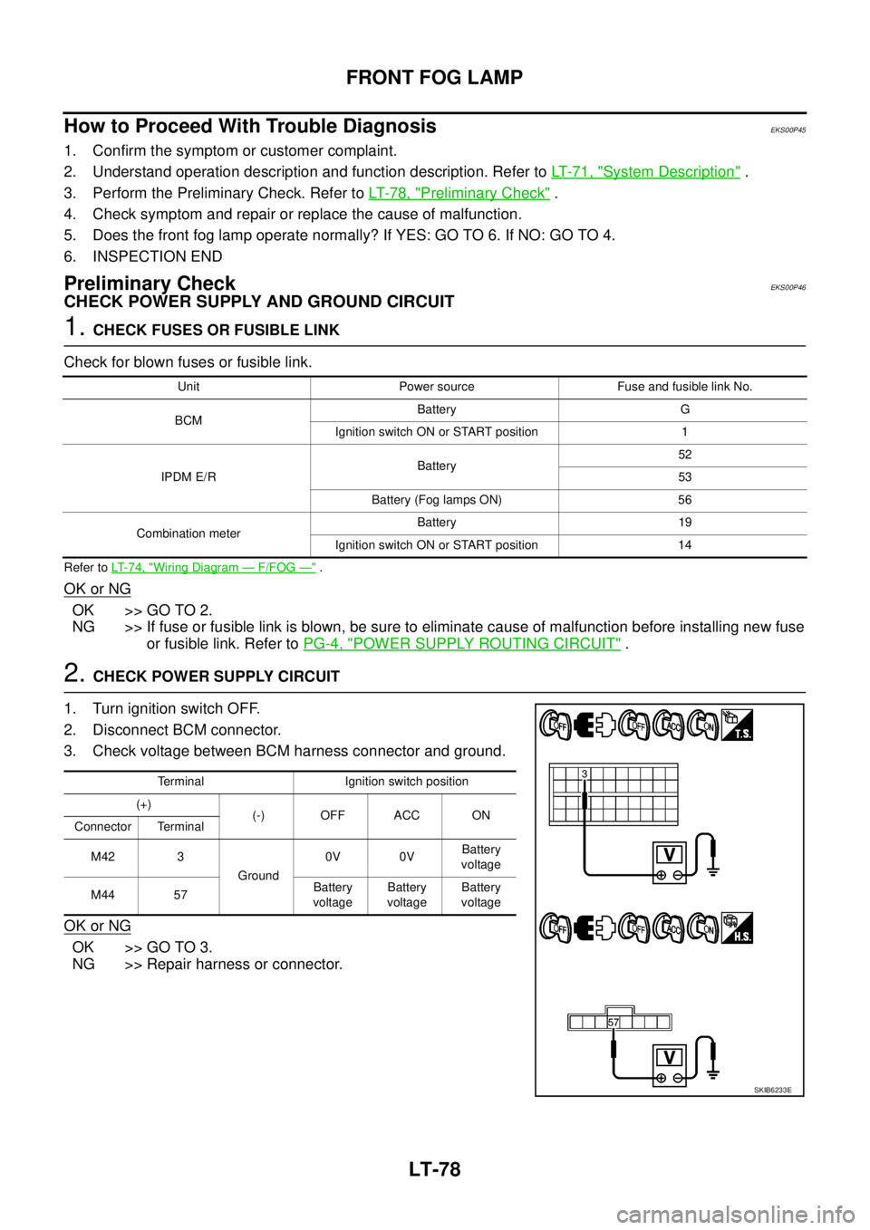
2.CHECK POWER SUPPLY CIRCUIT
1. Turn ignition switch OFF.
2. Disconnect BCM connector.
3. Check voltage between BCM harness connector and ground.
OK or NG
OK >> GO TO 3.
NG >> Repair harness or connector.
Unit Power source Fuse and fusible link No.
BCMBattery G
Ignition switch ON or START position 1
IPDM E/RBattery52
53
Battery (Fog lamps ON) 56
Combination meterBattery 19
Ignition switch ON or START position 14
Terminal Ignition switch position
(+)
(-) OFF ACC ON
Connector Terminal
M42 3
Ground0V 0VBattery
voltage
M44 57Battery
voltageBattery
voltageBattery
voltage
SKIB6233E
Page 2164 of 3171
FRONT FOG LAMP
LT-81
C
D
E
F
G
H
I
J
L
MA
B
LT
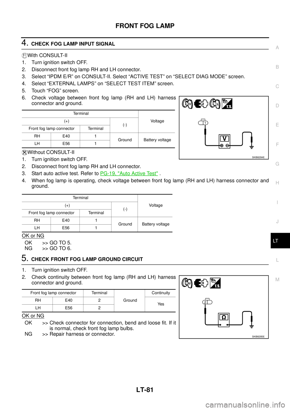
4.CHECK FOG LAMP INPUT SIGNAL
With CONSULT-II
1. Turn ignition switch OFF.
2. Disconnect front fog lamp RH and LH connector.
3. Select “IPDM E/R” on CONSULT-II. Select “ACTIVE TEST” on “SELECT DIAG MODE” screen.
4. Select “EXTERNAL LAMPS” on “SELECT TEST ITEM” screen.
5. Touch “FOG” screen.
6. Check voltage between front fog lamp (RH and LH) harness
connector and ground.
Without CONSULT-II
1. Turn ignition switch OFF.
2. Disconnect front fog lamp RH and LH connector.
3. Start auto active test. Refer toPG-19, "
Auto Active Test".
4. When fog lamp is operating, check voltage between front fog lamp (RH and LH) harness connector and
ground.
OK or NG
OK >> GO TO 5.
NG >> GO TO 6.
5.CHECK FRONT FOG LAMP GROUND CIRCUIT
1. Turn ignition switch OFF.
2. Check continuity between front fog lamp (RH and LH) harness
connector and ground.
OK or NG
OK >> Check connector for connection, bend and loose fit. If it
is normal, check front fog lamp bulbs.
NG >> Repair harness or connector.
Te r m i n a l
Voltage (+)
(-)
Front fog lamp connector Terminal
RH E40 1
Ground Battery voltage
LH E56 1
Te r m i n a l
Voltag e (+)
(-)
Front fog lamp connector Terminal
RH E40 1
Ground Battery voltage
LH E56 1
SKIB6284E
Front fog lamp connector Terminal
GroundContinuity
RH E40 2
Ye s
LH E56 2
SKIB6285E
Page 2165 of 3171
LT-82
FRONT FOG LAMP
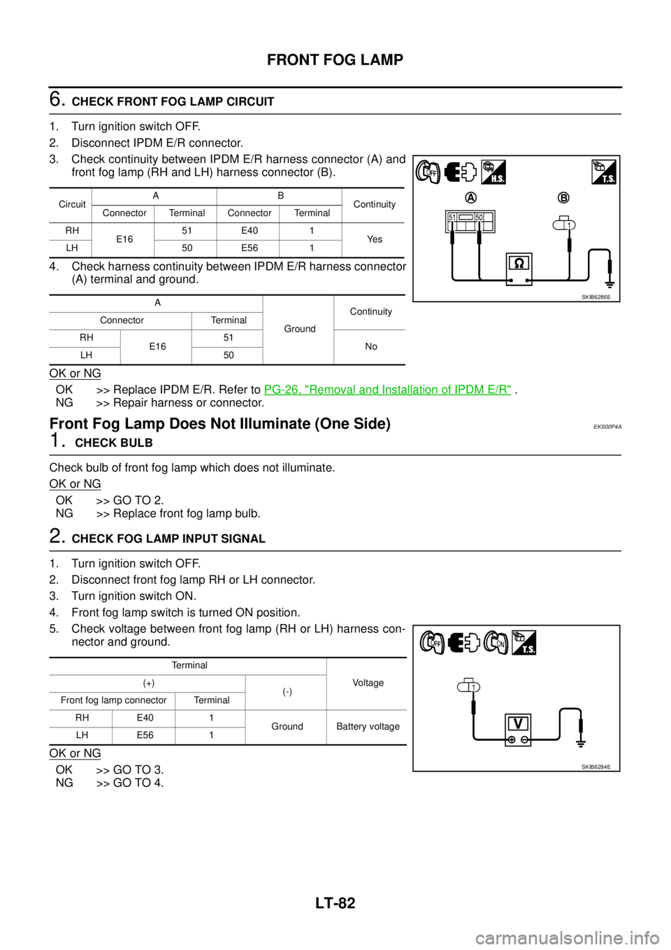
6.CHECK FRONT FOG LAMP CIRCUIT
1. Turn ignition switch OFF.
2. Disconnect IPDM E/R connector.
3. Check continuity between IPDM E/R harness connector (A) and
front fog lamp (RH and LH) harness connector (B).
4. Check harness continuity between IPDM E/R harness connector
(A) terminal and ground.
OK or NG
OK >> Replace IPDM E/R. Refer toPG-26, "Removal and Installation of IPDM E/R".
NG >> Repair harness or connector.
Front Fog Lamp Does Not Illuminate (One Side)EKS00P4A
1.CHECK BULB
Check bulb of front fog lamp which does not illuminate.
OK or NG
OK >> GO TO 2.
NG >> Replace front fog lamp bulb.
2.CHECK FOG LAMP INPUT SIGNAL
1. Turn ignition switch OFF.
2. Disconnect front fog lamp RH or LH connector.
3. Turn ignition switch ON.
4. Front fog lamp switch is turned ON position.
5. Check voltage between front fog lamp (RH or LH) harness con-
nector and ground.
OK or NG
OK >> GO TO 3.
NG >> GO TO 4.
CircuitAB
Continuity
Connector Terminal Connector Terminal
RH
E1651 E40 1
Ye s
LH 50 E56 1
A
GroundContinuity
Connector Terminal
RH
E1651
No
LH 50
SKIB6286E
Terminal
Voltage (+)
(-)
Front fog lamp connector Terminal
RH E40 1
Ground Battery voltage
LH E56 1
SKIB6284E