2005 NISSAN NAVARA coolant temperature
[x] Cancel search: coolant temperaturePage 1812 of 3171
![NISSAN NAVARA 2005 Repair Workshop Manual CAN COMMUNICATION
LAN-35
[CAN]
C
D
E
F
G
H
I
J
L
MA
B
LAN
Closed throttle position signal T R
Cooling fan speed request signal TR
Engine coolant temperature signal T R R
Engine speed signal T R R R
En NISSAN NAVARA 2005 Repair Workshop Manual CAN COMMUNICATION
LAN-35
[CAN]
C
D
E
F
G
H
I
J
L
MA
B
LAN
Closed throttle position signal T R
Cooling fan speed request signal TR
Engine coolant temperature signal T R R
Engine speed signal T R R R
En](/manual-img/5/57362/w960_57362-1811.png)
CAN COMMUNICATION
LAN-35
[CAN]
C
D
E
F
G
H
I
J
L
MA
B
LAN
Closed throttle position signal T R
Cooling fan speed request signal TR
Engine coolant temperature signal T R R
Engine speed signal T R R R
Engine status signal T R R
Fuel consumption monitor signalTR
RT
Glow indicator signal T R
Glow relay signal T R
Malfunction indicator signal T R
Wide open throttle position signal T R
A/T fluid temperature sensor signal T R
A/T position indicator lamp signal T R
OD OFF indicator lamp signal T R
Output shaft revolution signal R T
Turbine revolution signal R T
A/C switch/indicator signal T R
PTC heater signal R T
A/C switch signal R R T
Buzzer output signal T R
Day time running light request signal R T R R
Door switch signalTR R
Front fog light request signal R T R R
Front wiper request signal T R
High beam request signal T R R
Horn chirp signalTR
Low beam request signal T R
Position light request signal T R R
Rear fog light request signal R T R
Rear window defogger switch signal R T R
Sleep wake up signal T R R
Theft warning horn request signal T R
Trailer lamp signalTR
Turn indicator signal T R
1st position switch signal R T
Distance to empty signal R T
Fuel level low warning signal R T
Overdrive control switch signal R T
Stop lamp switch signal R T
ABS operation signal R T
ABS warning lamp signalRT Signals ECM TCMNAVI
control
unitFront air
controlBCMCombi-
nation
meterABS
actuator
and elec-
tric unit
(control
unit)IPDM
E/R
Page 1816 of 3171
![NISSAN NAVARA 2005 Repair Workshop Manual CAN COMMUNICATION
LAN-39
[CAN]
C
D
E
F
G
H
I
J
L
MA
B
LAN
Input/output signal chart
T: Transmit R: Receive
Signals ECMNAVI
control
unitDiffer-
ential
lock
control
unitFront air
con-
trol
*1BCMCombi-
n NISSAN NAVARA 2005 Repair Workshop Manual CAN COMMUNICATION
LAN-39
[CAN]
C
D
E
F
G
H
I
J
L
MA
B
LAN
Input/output signal chart
T: Transmit R: Receive
Signals ECMNAVI
control
unitDiffer-
ential
lock
control
unitFront air
con-
trol
*1BCMCombi-
n](/manual-img/5/57362/w960_57362-1815.png)
CAN COMMUNICATION
LAN-39
[CAN]
C
D
E
F
G
H
I
J
L
MA
B
LAN
Input/output signal chart
T: Transmit R: Receive
Signals ECMNAVI
control
unitDiffer-
ential
lock
control
unitFront air
con-
trol
*1BCMCombi-
nation
meterTrans-
fer con-
trol unitABS
actua-
tor and
electric
unit
(control
unit)IPDM
E/R
A/C compressor request signal TR
ASCD CRUISE lamp signal T R
ASCD SET lamp signal T R
Cooling fan speed request signal TR
Engine coolant temperature signal T R R
Engine speed signal T R R R
Engine status signal T R R
Fuel consumption monitor signalTR
RT
Glow indicator signal T R
Glow relay signal T R
Malfunction indicator signal T R
A/C switch/indicator signal T
R
*2
Differential lock indicator signal T R
Differential lock switch signal T R
PTC heater signal
*3RT
A/C switch signal R
R
*2T
Buzzer output signal T R
Day time running light request signal R T R R
Door switch signal T R R
Front fog light request signal R T R R
Front wiper request signal T R
High beam request signal T R R
Horn chirp signal T R
Low beam request signal T R
Position light request signal T R R
Rear fog light request signal R T R
Rear window defogger switch signal R T R
Sleep wake up signal T R R
Theft warning horn request signal T R
Trailer lamp signal T R
Turn indicator signal T R
Distance to empty signal R T
Fuel level low warning signal R T
4WD shift switch signal R T
ABS warning lamp signal R T
Stop lamp switch signalRT
Page 1819 of 3171
![NISSAN NAVARA 2005 Repair Workshop Manual LAN-42
[CAN]
CAN COMMUNICATION
Engine coolant temperature signal T R R
Engine speed signal T R R R R
Engine status signal T R R
Fuel consumption monitor signalTR
RT
Glow indicator signal T R
Glow rela NISSAN NAVARA 2005 Repair Workshop Manual LAN-42
[CAN]
CAN COMMUNICATION
Engine coolant temperature signal T R R
Engine speed signal T R R R R
Engine status signal T R R
Fuel consumption monitor signalTR
RT
Glow indicator signal T R
Glow rela](/manual-img/5/57362/w960_57362-1818.png)
LAN-42
[CAN]
CAN COMMUNICATION
Engine coolant temperature signal T R R
Engine speed signal T R R R R
Engine status signal T R R
Fuel consumption monitor signalTR
RT
Glow indicator signal T R
Glow relay signal T R
Malfunction indicator signal T R
Wide open throttle position signal T R
A/T fluid temperature sensor signal T R
A/T position indicator lamp signal T R R
OD OFF indicator lamp signal T R
Output shaft revolution signal R T R
Turbine revolution signal R T
A/C switch/indicator signal T R
Differential lock indicator signal T R
Differential lock switch signal T R
PTC heater signal
*RT
A/C switch signal R R T
Buzzer output signal T R
Day time running light request signal R T R R
Door switch signal T R R
Front fog light request signal R T R R
Front wiper request signal T R
High beam request signal T R R
Horn chirp signalTR
Low beam request signal T R
Position light request signal T R R
Rear fog light request signal R T R
Rear window defogger switch signal R T R
Sleepwakeupsignal T R R
Theft warning horn request signal T R
Trailer lamp signal T R
Turn indicator signal T R
1st position switch signal R T
Distance to empty signal R T
Fuel level low warning signal R T
Overdrive control switch signal R T
Stop lamp switch signal R TSignals ECM TCMNAVI
con-
trol
unitDiffer-
ential
lock
con-
trol
unitFront
air
controlBCMCom-
bina-
tion
meterTrans-
fer
con-
trol
unitABS
actua-
tor and
elec-
tric unit
(con-
trol
unit)IPDM
E/R
Page 2291 of 3171

MA-16
RECOMMENDED FLUIDS AND LUBRICANTS
Engine Coolant Mixture Ratio
ELS001JC
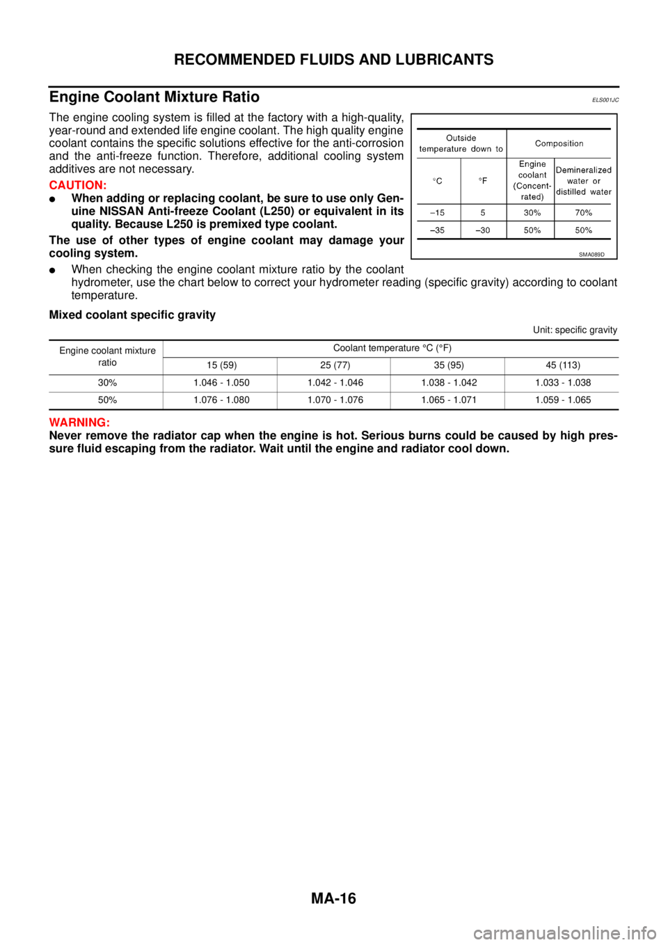
The engine cooling system is filled at the factory with a high-quality,
year-round and extended life engine coolant. The high quality engine
coolant contains the specific solutions effective for the anti-corrosion
and the anti-freeze function. Therefore, additional cooling system
additives are not necessary.
CAUTION:
lWhen adding or replacing coolant, be sure to use only Gen-
uine NISSAN Anti-freeze Coolant (L250) or equivalent in its
quality. Because L250 is premixed type coolant.
The use of other types of engine coolant may damage your
cooling system.
lWhen checking the engine coolant mixture ratio by the coolant
hydrometer, use the chart below to correct your hydrometer reading (specific gravity) according to coolant
temperature.
Mixed coolant specific gravity
Unit: specific gravity
WARNING:
Never remove the radiator cap when the engine is hot. Serious burns could be caused by high pres-
sure fluid escaping from the radiator. Wait until the engine and radiator cool down.
SMA089D
Engine coolant mixture
ratioCoolant temperature°C(°F)
15 (59) 25 (77) 35 (95) 45 (113)
30% 1.046 - 1.050 1.042 - 1.046 1.038 - 1.042 1.033 - 1.038
50% 1.076 - 1.080 1.070 - 1.076 1.065 - 1.071 1.059 - 1.065
Page 2295 of 3171

MA-20
ENGINE MAINTENANCE
REFILLING ENGINE COOLANT
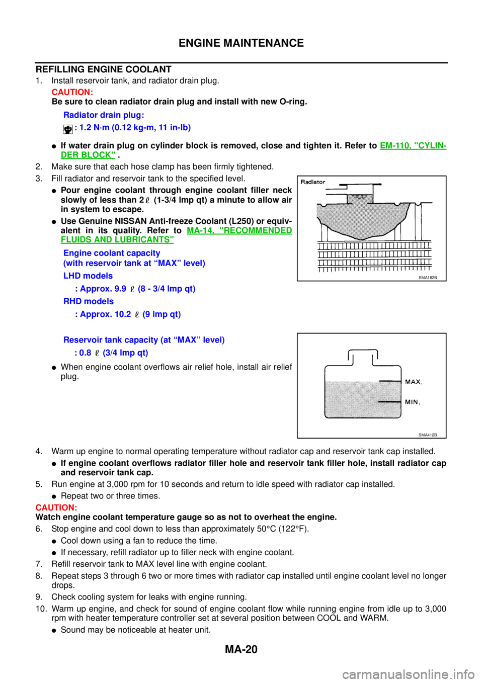
1. Install reservoir tank, and radiator drain plug.
CAUTION:
Be sure to clean radiator drain plug and install with new O-ring.
lIf water drain plug on cylinder block is removed, close and tighten it. Refer toEM-110, "CYLIN-
DER BLOCK".
2. Make sure that each hose clamp has been firmly tightened.
3. Fill radiator and reservoir tank to the specified level.
lPour engine coolant through engine coolant filler neck
slowly of less than 2 (1-3/4 lmp qt) a minute to allow air
in system to escape.
lUse Genuine NISSAN Anti-freeze Coolant (L250) or equiv-
alent in its quality. Refer toMA-14, "
RECOMMENDED
FLUIDS AND LUBRICANTS"
lWhen engine coolant overflows air relief hole, install air relief
plug.
4. Warm up engine to normal operating temperature without radiator cap and reservoir tank cap installed.
lIf engine coolant overflows radiator filler hole and reservoir tank filler hole, install radiator cap
and reservoir tank cap.
5. Run engine at 3,000 rpm for 10 seconds and return to idle speed with radiator cap installed.
lRepeat two or three times.
CAUTION:
Watch engine coolant temperature gauge so as not to overheat the engine.
6. Stop engine and cool down to less than approximately 50°C(122°F).
lCool down using a fan to reduce the time.
lIf necessary, refill radiator up to filler neck with engine coolant.
7. Refill reservoir tank to MAX level line with engine coolant.
8. Repeat steps 3 through 6 two or more times with radiator cap installed until engine coolant level no longer
drops.
9. Check cooling system for leaks with engine running.
10. Warm up engine, and check for sound of engine coolant flow while running engine from idle up to 3,000
rpm with heater temperature controller set at several position between COOL and WARM.
lSound may be noticeable at heater unit.Radiator drain plug:
: 1.2 N·m (0.12 kg-m, 11 in-lb)
Engine coolant capacity
(with reservoir tank at “MAX” level)
LHD models
: Approx. 9.9 (8 - 3/4 lmp qt)
RHD models
: Approx. 10.2 (9 lmp qt)
SMA182B
Reservoir tank capacity (at “MAX” level)
: 0.8 (3/4 lmp qt)
SMA412B
Page 2296 of 3171

ENGINE MAINTENANCE
MA-21
C
D
E
F
G
H
I
J
K
MA
B
MA
11. Repeat step 10 three times.
12. If sound is heard, bleed air from cooling system by repeating steps 3 through 6 until engine coolant level
no longer drops.
FLUSHING COOLING SYSTEM
1. Fill radiator with water until water spills from the air relief hole, then close air relief plug. Fill radiator and
reservoir tank with water and reinstall radiator cap and reservoir tank cap.
2. Run engine and warm it up to normal operating temperature.
3. Rev engine two or three times under no-load.
4. Stop engine and wait until it cools down.
5. Drain water from the system. Refer toMA-19, "
DRAINING ENGINE COOLANT".
6. Repeat steps 1 through 5 until clear water begins to drain from radiator.
Checking Cooling SystemELS001JR
WARNING:
Never remove the radiator cap and reservoir tank cap when the engine is hot. Serious burns could
occur from high pressure engine coolant escaping from the radiator and the reservoir tank. Wrap a
thick cloth around the cap. Slowly turn it a quarter turn to allow built-up pressure to escape. Carefully
remove the cap by turning it all the way.
CHECKING COOLING SYSTEM HOSES
Check hoses for improper attachment, leaks, cracks, damage, loose connections, chafing and deterioration.
CHECKING RADIATOR
Check radiator for mud or clogging. If necessary, clean radiator as follows.
lBe careful not to bend or damage the radiator fins.
lWhen radiator is cleaned without removal, remove all surrounding parts such as cooling fan, radiator
shroud and horns. Then tape the harness and connectors to prevent water from entering.
1. Apply water by hose to the back side of the radiator core vertically downwards.
2. Apply water again to all radiator core surface once per minute.
3. Stop washing if any stains no longer flow out from the radiator.
4. Blow air into the back side of radiator core vertically downwards.
lUse compressed air lower than 490 kpa (4.9 bar, 5 kg/cm2, 71psi) and keep distance more than 30
cm(11.8 in).
5. Blow air again into all the radiator core surface once per minute until no water sprays out.
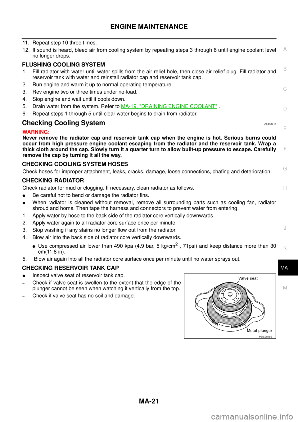
CHECKING RESERVOIR TANK CAP
lInspect valve seat of reservoir tank cap.
–Check if valve seat is swollen to the extent that the edge of the
plunger cannot be seen when watching it vertically from the top.
–Check if valve seat has no soil and damage.
PBIC2816E
Page 2413 of 3171

MTC-26
AIR CONDITIONER CONTROL
AIR CONDITIONER CONTROL
PFP:27500
DescriptionEJS005FW
The front air control provides regulation of the vehicle's interior temperature. The system is based on the posi-
tion of the front air controls temperature switch selected by the driver. This is done by utilizing a microcom-
puter, also referred to as the front air control, which receives input signals from the following three sensors:
lIntake sensor
lPBR (Position Balanced Resistor).
The front air control uses these signals (including the set position of the temperature switch) to control:
lOutlet air volume
lAir temperature
lAir distribution
The front air control is used to select:
lOutlet air volume
lAir temperature/distribution
OperationEJS005FX
AIR MIX DOOR CONTROL
The air mix door is controlled so that in-vehicle temperature changed based on the position of the temperature
switch.
BLOWER SPEED CONTROL
Blower speed is controlled based on front blower switch settings.
When blower switch is turned, the blower motor starts and increases air flow volume each time the blower
switch is turned counterclockwise, and decreases air flow volume each time the blower switch is turned coun-
terclockwise.
When engine coolant temperature is low, the blower motor operation is delayed to prevent cool air from flow-
ing.
INTAKE DOORS CONTROL
The intake doors are controlled by the recirculation switch setting, and the mode (defroster) switch setting.
MODE DOOR CONTROL
The mode door is controlled by the position of the mode switch.
DEFROSTER DOOR CONTROL
The defroster door is controlled by: Turning the defroster dial to front defroster.
Page 2597 of 3171

PG-68
HARNESS
Wiring Diagram Codes (Cell Codes)
EKS00LJ9
Use the chart below to find out what each wiring diagram code stands for.
Refer to the wiring diagram code in the alphabetical index to find the location (page number) of each wiring
diagram.
Code Section Wiring Diagram Name
A/C,A ATC Auto Air Conditioner
A/C,M MTC Manual Air Conditioner
ABS BRC Anti-lock Brake System
APP1PW EC Accelerator Pedal Position Sensor 1 Power
APP2PW EC Accelerator Pedal Position Sensor 2 Power
APPS1 EC Accelerator Pedal Position Sensor 1
APPS2 EC Accelerator Pedal Position Sensor 2
APPS3 EC Accelerator Pedal Position Sensor
ASC/BS EC ASCD Brake Switch
ASC/SW EC ASCD Steering Switch
ASCBOF EC ASCD Brake Switch
ASCIND EC ASCD Indicator
AT/IND DI A/T Indicator Lamp
AUDIO AV Audio
AUTO/L LT Auto Lignt System
BACK/L LT Back-up Lamp
BOOST EC Turbocharger Boost Sensor
CAN AT CAN Communication Line
CAN EC CAN Communication Line
CAN LAN CAN System
CHARGE SC Charging System
CHIME DI Warning Chime
CIGER WW Cigarette Lighter
CKPS EC Crankshaft Position Sensor
CMPS EC Camshaft Position Sensor
COMBSW LT Combination Switch
COMM AV Audio Visual Communication Line
COMPAS DI Compass
COOL/F EC Cooling Fan Control
D/LOCK BL Power Door Lock
DIFLOC RFD Rear Final Drive
DEF GW Rear Window Defogger
DTRL LT Headlamp — With Daytime Running Light System
ECMRLY EC ECM Relay
ECTS EC Engine Coolant Temperature Sensor
EGRVLV EC EGR Volume Control System
EMNT EC Electronic Controlled Engine Mount Control Solenoid Valve
F/FOG LT Front Fog Lamp
F/PUMP EC Fuel Pump
FRPS EC Fuel Rail Pressure Sensor
FTS AT A/T Fluid Temperature Sensor