Page 1455 of 3171
SECONDARY TIMING CHAIN
EM-73
C
D
E
F
G
H
I
J
K
L
MA
EM
SECONDARY TIMING CHAINPFP:13028
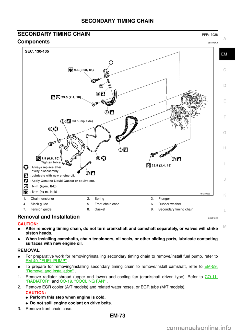
ComponentsEBS01EKA
Removal and InstallationEBS01E68
CAUTION:
lAfter removing timing chain, do not turn crankshaft and camshaft separately, or valves will strike
piston heads.
lWhen installing camshafts, chain tensioners, oil seals, or other sliding parts, lubricate contacting
surfaces with new engine oil.
REMOVAL
lFor preparative work for removing/installing secondary timing chain to remove/install fuel pump, refer to
EM-49, "
FUEL PUMP".
lTo prepare for removing/installing secondary timing chain to remove/install camshaft, refer toEM-59,
"Removal and Installation".
1. Remove radiator shroud (upper and lower) and cooling fan (crankshaft driven type). Refer toCO-11,
"RADIATOR"andCO-19, "COOLING FAN".
2. Remove EGR cooler (A/T models) and related water hoses, or EGR tube (M/T models).
CAUTION:
lPerform this step when engine is cold.
lDo not spill engine coolant on drive belts.
3. Remove front chain case.
1. Chain tensioner 2. Spring 3. Plunger
4. Slack guide 5. Front chain case 6. Rubber washer
7. Tension guide 8. Gasket 9. Secondary timing chain
PBIC2326E
Page 1456 of 3171
EM-74
SECONDARY TIMING CHAIN
lLoosen fixing bolts in reverse order of that shown in the figure
and remove them.
CAUTION:
lWhile front chain case is removed, cover openings to
prevent entry of foreign material into engine.
lDo not remove two mass dampers on the back of
cover.
4. Set the No. 1 piston to TDC on its compression stroke.
lTurn crankshaft pulley clockwise so that the alignment mark
(punched mark) on each camshaft sprocket is positioned as
showninthefigure.
lNo position indicator is provided on crankshaft pulley.
lWhen installing, color coded links on secondary timing
chain can be used as alignment marks. Marking may not
be necessary for removal; however, make alignment
marks as required because the alignment mark on fuel
pump sprocket may not be easy to see.
5. Remove chain tensioner.
a. Push the plunger of chain tensioner and keep it pressed with a
push pin.
JEM121G
SBIA0189E
SEM515G
JEM124G
Page 1459 of 3171
SECONDARY TIMING CHAIN
EM-77
C
D
E
F
G
H
I
J
K
L
MA
EM
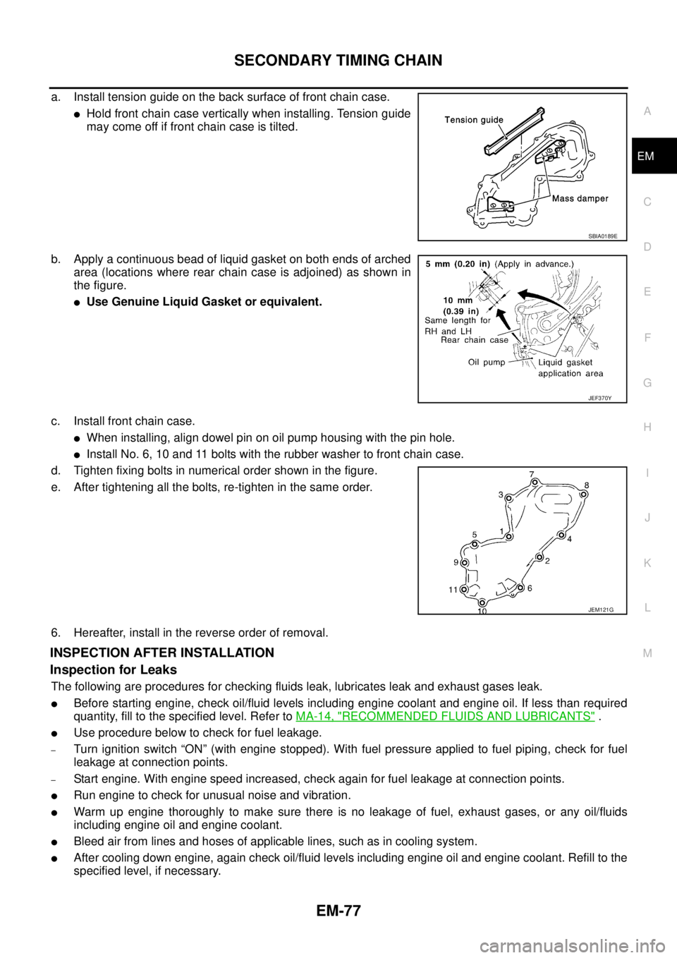
a. Install tension guide on the back surface of front chain case.
lHold front chain case vertically when installing. Tension guide
may come off if front chain case is tilted.
b. Apply a continuous bead of liquid gasket on both ends of arched
area (locations where rear chain case is adjoined) as shown in
the figure.
lUse Genuine Liquid Gasket or equivalent.
c. Install front chain case.
lWhen installing, align dowel pin on oil pump housing with the pin hole.
lInstall No. 6, 10 and 11 bolts with the rubber washer to front chain case.
d. Tighten fixing bolts in numerical order shown in the figure.
e. After tightening all the bolts, re-tighten in the same order.
6. Hereafter, install in the reverse order of removal.
INSPECTION AFTER INSTALLATION
Inspection for Leaks
The following are procedures for checking fluids leak, lubricates leak and exhaust gases leak.
lBefore starting engine, check oil/fluid levels including engine coolant and engine oil. If less than required
quantity, fill to the specified level. Refer toMA-14, "
RECOMMENDED FLUIDS AND LUBRICANTS".
lUse procedure below to check for fuel leakage.
–Turn ignition switch “ON” (with engine stopped). With fuel pressure applied to fuel piping, check for fuel
leakage at connection points.
–Start engine. With engine speed increased, check again for fuel leakage at connection points.
lRun engine to check for unusual noise and vibration.
lWarm up engine thoroughly to make sure there is no leakage of fuel, exhaust gases, or any oil/fluids
including engine oil and engine coolant.
lBleed air from lines and hoses of applicable lines, such as in cooling system.
lAfter cooling down engine, again check oil/fluid levels including engine oil and engine coolant. Refill to the
specified level, if necessary.
SBIA0189E
JEF370Y
JEM121G
Page 1460 of 3171
EM-78
SECONDARY TIMING CHAIN
Summary of the inspection items:
*1: Transmission/transaxle/CVT fluid, power steering fluid, brake fluid, etc.
*2: Check engine oil level 10 minutes after engine stopped.Item Before starting engine Engine running After engine stopped
Engine coolant Level Leakage Level
Engine oil Level Leakage Level (*2)
Other oils and fluid (*1) Level Leakage Level
Fuel Leakage Leakage Leakage
Exhaust gases — Leakage —
Page 1462 of 3171
EM-80
PRIMARY TIMING CHAIN
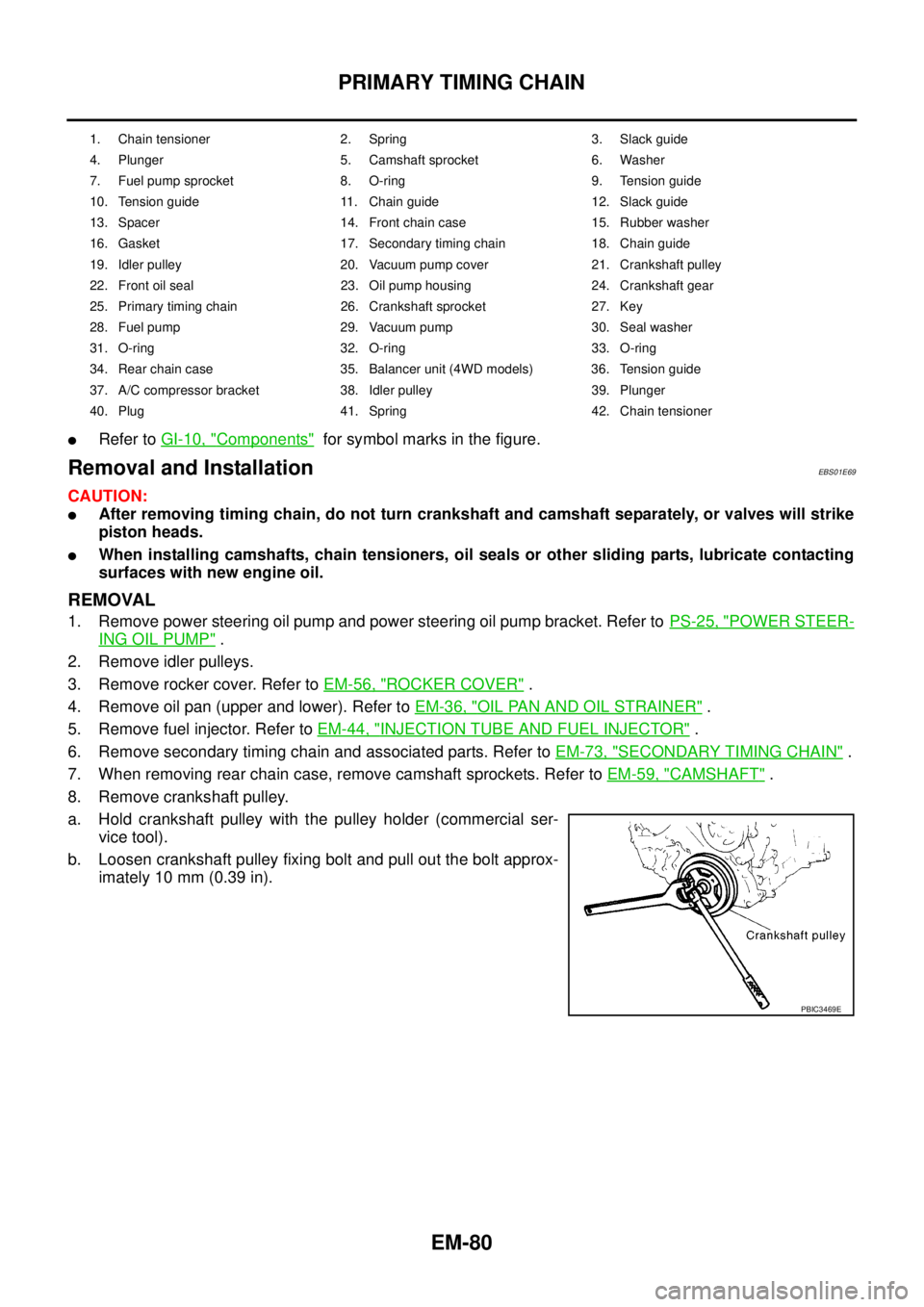
lRefer toGI-10, "Components"for symbol marks in the figure.
Removal and InstallationEBS01E69
CAUTION:
lAfter removing timing chain, do not turn crankshaft and camshaft separately, or valves will strike
piston heads.
lWhen installing camshafts, chain tensioners, oil seals or other sliding parts, lubricate contacting
surfaces with new engine oil.
REMOVAL
1. Remove power steering oil pump and power steering oil pump bracket. Refer toPS-25, "POWER STEER-
ING OIL PUMP".
2. Remove idler pulleys.
3. Remove rocker cover. Refer toEM-56, "
ROCKER COVER".
4. Remove oil pan (upper and lower). Refer toEM-36, "
OIL PAN AND OIL STRAINER".
5. Remove fuel injector. Refer toEM-44, "
INJECTION TUBE AND FUEL INJECTOR".
6. Remove secondary timing chain and associated parts. Refer toEM-73, "
SECONDARY TIMING CHAIN".
7. When removing rear chain case, remove camshaft sprockets. Refer toEM-59, "
CAMSHAFT".
8. Remove crankshaft pulley.
a. Hold crankshaft pulley with the pulley holder (commercial ser-
vice tool).
b. Loosen crankshaft pulley fixing bolt and pull out the bolt approx-
imately 10 mm (0.39 in).
1. Chain tensioner 2. Spring 3. Slack guide
4. Plunger 5. Camshaft sprocket 6. Washer
7. Fuel pump sprocket 8. O-ring 9. Tension guide
10. Tension guide 11. Chain guide 12. Slack guide
13. Spacer 14. Front chain case 15. Rubber washer
16. Gasket 17. Secondary timing chain 18. Chain guide
19. Idler pulley 20. Vacuum pump cover 21. Crankshaft pulley
22. Front oil seal 23. Oil pump housing 24. Crankshaft gear
25. Primary timing chain 26. Crankshaft sprocket 27. Key
28. Fuel pump 29. Vacuum pump 30. Seal washer
31. O-ring 32. O-ring 33. O-ring
34. Rear chain case 35. Balancer unit (4WD models) 36. Tension guide
37. A/C compressor bracket 38. Idler pulley 39. Plunger
40. Plug 41. Spring 42. Chain tensioner
PBIC3469E
Page 1466 of 3171
EM-84
PRIMARY TIMING CHAIN
20. Remove rear chain case.
lLoosen fixing bolts in the reverse order of that shown in the
figure and remove them.
lU s e t h e s e a l c u t t e r [ S S T: K V 1 0 1111 0 0 ] f o r r e m o v a l .
21. Remove balancer unit (4WD models).
lLoosen mounting bolts in the reverse order as shown in the
figure.
INSPECTION AFTER REMOVAL
Timing Chain
Check for cracks and excessive wear at roller links. Replace
timing chain if necessary.
SBIA0211E
: Engine front
PBIC4049E
SEM984C
Page 1467 of 3171
PRIMARY TIMING CHAIN
EM-85
C
D
E
F
G
H
I
J
K
L
MA
EM
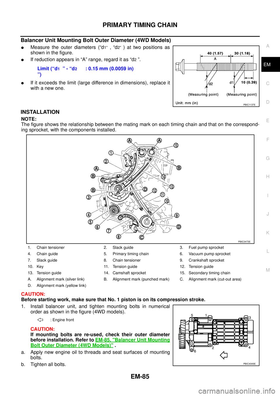
Balancer Unit Mounting Bolt Outer Diameter (4WD Models)
lMeasure the outer diameters (“d1”,“d2”)attwopositionsas
showninthefigure.
lIf reduction appears in “A” range, regard it as “d2”.
lIf it exceeds the limit (large difference in dimensions), replace it
with a new one.
INSTALLATION
NOTE:
The figure shows the relationship between the mating mark on each timing chain and that on the correspond-
ing sprocket, with the components installed.
CAUTION:
Before starting work, make sure that No. 1 piston is on its compression stroke.
1. Install balancer unit, and tighten mounting bolts in numerical
order as shown in the figure (4WD models).
CAUTION:
If mounting bolts are re-used, check their outer diameter
before installation. Refer toEM-85, "
Balancer Unit Mounting
Bolt Outer Diameter (4WD Models)".
a. Apply new engine oil to threads and seat surfaces of mounting
bolts.
b. Tighten all bolts.Limit (“d
1”-“d2
”): 0.15 mm (0.0059 in)
PBIC1137E
1. Chain tensioner 2. Slack guide 3. Fuel pump sprocket
4. Chain guide 5. Primary timing chain 6. Vacuum pump sprocket
7. Slack guide 8. Chain tensioner 9. Crankshaft sprocket
10. Key 11. Tension guide 12. Tension guide
13. Tension guide 14. Camshaft sprocket 15. Secondary timing chain
A. Alignment mark (silver link) B. Alignment mark (punched mark) C. Alignment mark (cut-out area)
D. Alignment mark (yellow link)
: Engine front
PBIC3473E
PBIC4049E
Page 1468 of 3171
EM-86
PRIMARY TIMING CHAIN
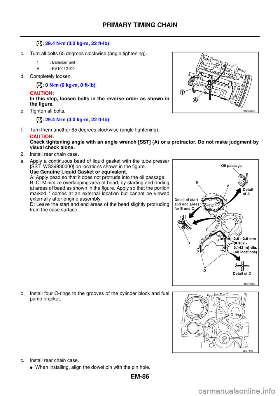
c. Turn all bolts 65 degrees clockwise (angle tightening).
d. Completely loosen.
CAUTION:
In this step, loosen bolts in the reverse order as shown in
the figure.
e. Tighten all bolts.
f. Turn them another 65 degrees clockwise (angle tightening).
CAUTION:
Check tightening angle with an angle wrench [SST] (A) or a protractor. Do not make judgment by
visual check alone.
2. Install rear chain case.
a. Apply a continuous bead of liquid gasket with the tube presser
[SST: WS39930000] on locations shown in the figure.
Use Genuine Liquid Gasket or equivalent.
A: Apply bead so that it does not protrude into the oil passage.
B, C: Minimize overlapping area of bead, by starting and ending
at areas of bead as shown in the figure. Apply so that the portion
marked * comes at an external location but cannot be viewed
externally after engine assembly.
D: Leave the start and end areas of the bead slightly protruding
from the case surface.
b. Install four O-rings to the grooves of the cylinder block and fuel
pump bracket.
c. Install rear chain case.
lWhen installing, align the dowel pin with the pin hole.: 29.4 N·m (3.0 kg-m, 22 ft-lb)
1 : Balancer unit
A : KV10112100
: 0 N·m (0 kg-m, 0 ft-lb)
: 29.4 N·m (3.0 kg-m, 22 ft-lb)
PBIC3474E
PBIC1255E
JEM141G