2005 NISSAN NAVARA differential
[x] Cancel search: differentialPage 1580 of 3171
FFD-34
FRONT FINAL DRIVE ASSEMBLY
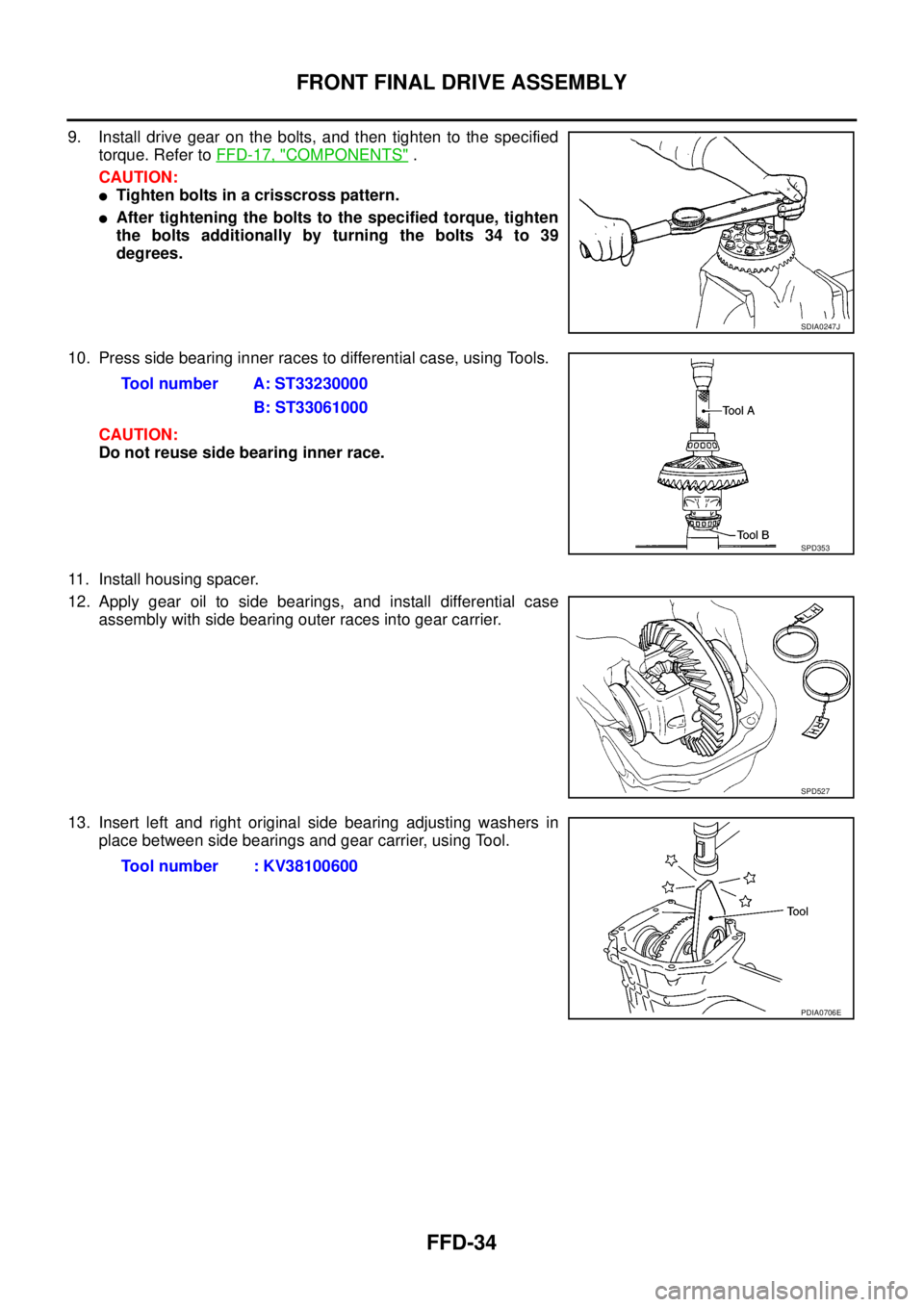
9. Install drive gear on the bolts, and then tighten to the specified
torque. Refer toFFD-17, "
COMPONENTS".
CAUTION:
lTighten bolts in a crisscross pattern.
lAfter tightening the bolts to the specified torque, tighten
the bolts additionally by turning the bolts 34 to 39
degrees.
10. Press side bearing inner races to differential case, using Tools.
CAUTION:
Do not reuse side bearing inner race.
11. Install housing spacer.
12. Apply gear oil to side bearings, and install differential case
assembly with side bearing outer races into gear carrier.
13. Insert left and right original side bearing adjusting washers in
place between side bearings and gear carrier, using Tool.
SDIA0247J
Tool number A: ST33230000
B: ST33061000
SPD353
SPD527
Tool number : KV38100600
PDIA0706E
Page 1583 of 3171
SERVICE DATA AND SPECIFICATIONS (SDS)
FFD-37
C
E
F
G
H
I
J
K
L
MA
B
FFD
SERVICE DATA AND SPECIFICATIONS (SDS)PFP:00030
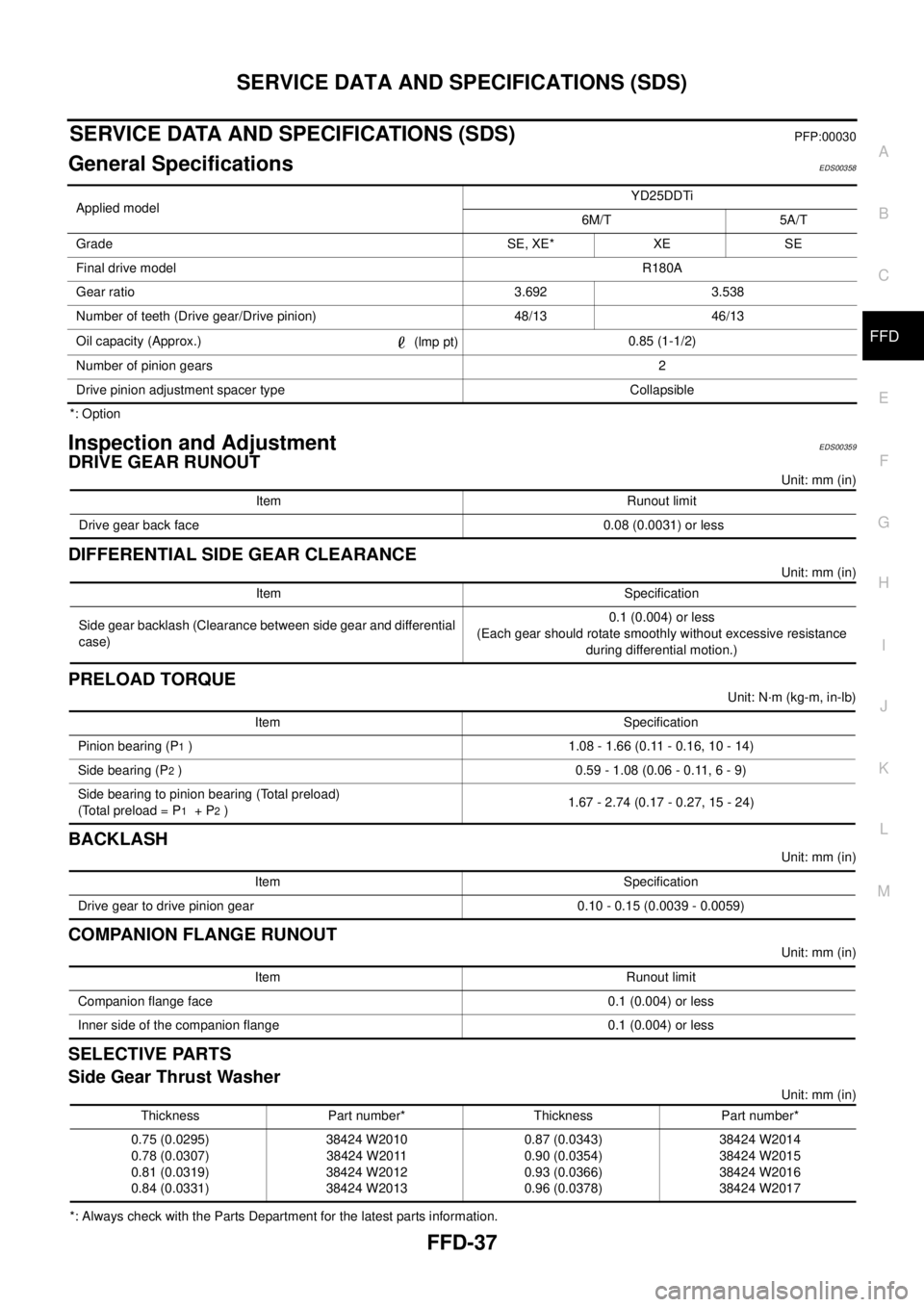
General SpecificationsEDS00358
*: Option
Inspection and AdjustmentEDS00359
DRIVE GEAR RUNOUT
Unit: mm (in)
DIFFERENTIAL SIDE GEAR CLEARANCE
Unit: mm (in)
PRELOAD TORQUE
Unit: N·m (kg-m, in-lb)
BACKLASH
Unit: mm (in)
COMPANION FLANGE RUNOUT
Unit: mm (in)
SELECTIVE PARTS
Side Gear Thrust Washer
Unit: mm (in)
*: Always check with the Parts Department for the latest parts information.Applied modelYD25DDTi
6M/T 5A/T
Grade SE, XE* XE SE
Final drive modelR180A
Gear ratio 3.692 3.538
Number of teeth (Drive gear/Drive pinion) 48/13 46/13
Oil capacity (Approx.)
(lmp pt)0.85 (1-1/2)
Number of pinion gears2
Drive pinion adjustment spacer type Collapsible
Item Runout limit
Drive gear back face 0.08 (0.0031) or less
Item Specification
Side gear backlash (Clearance between side gear and differential
case)0.1 (0.004) or less
(Each gear should rotate smoothly without excessive resistance
during differential motion.)
Item Specification
Pinion bearing (P
1) 1.08 - 1.66 (0.11 - 0.16, 10 - 14)
Side bearing (P
2) 0.59 - 1.08 (0.06 - 0.11, 6 - 9)
Side bearing to pinion bearing (Total preload)
(Total preload = P
1+P2)1.67 - 2.74 (0.17 - 0.27, 15 - 24)
Item Specification
Drive gear to drive pinion gear 0.10 - 0.15 (0.0039 - 0.0059)
Item Runout limit
Companion flange face 0.1 (0.004) or less
Inner side of the companion flange 0.1 (0.004) or less
Thickness Part number* Thickness Part number*
0.75 (0.0295)
0.78 (0.0307)
0.81 (0.0319)
0.84 (0.0331)38424 W2010
38424 W2011
38424 W2012
38424 W20130.87 (0.0343)
0.90 (0.0354)
0.93 (0.0366)
0.96 (0.0378)38424 W2014
38424 W2015
38424 W2016
38424 W2017
Page 1605 of 3171
NOISE, VIBRATION, AND HARSHNESS (NVH) TROUBLESHOOTING
FSU-5
C
D
F
G
H
I
J
K
L
MA
B
FSU
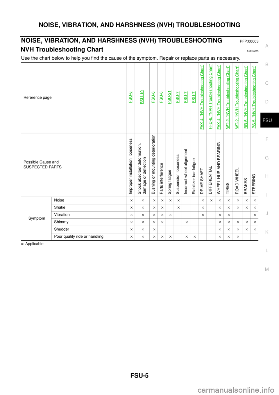
NOISE, VIBRATION, AND HARSHNESS (NVH) TROUBLESHOOTINGPFP:00003
NVH Troubleshooting ChartEES002KK
Use the chart below to help you find the cause of the symptom. Repair or replace parts as necessary.
x: ApplicableReference page
FSU-6FSU-10FSU-6FSU-6FSU-21FSU-7FSU-7FSU-7
FAX-4, "
NVH Troubleshooting Chart
"
FFD-6, "
NVH Troubleshooting Chart
"
FAX-4, "
NVH Troubleshooting Chart
"
WT-2, "
NVH Troubleshooting Chart
"
WT-2, "
NVH Troubleshooting Chart
"
BR-5, "
NVH Troubleshooting Chart
"
PS-5, "
NVH Troubleshooting Chart
"
Possible Cause and
SUSPECTED PARTS
Improper installation, looseness
Shock absorber deformation,
damage or deflection
Bushing or mounting deterioration
Parts interference
Spring fatigue
Suspension looseness
Incorrect wheel alignment
Stabilizer bar fatigue
DRIVE SHAFT
DIFFERENTIAL
WHEEL HUB AND BEARING
TIRES
ROAD WHEEL
BRAKES
STEERING
SymptomNoise´ ´ ´´´´ ´ ´ ´ ´ ´ ´´
Shake´´´´ ´ ´ ´´´´´
Vibration´ ´ ´´´ ´ ´ ´ ´
Shimmy´´´´ ´ ´´´´´
Shudder´´´ ´´´´´
Poor quality ride or handling´ ´ ´´´ ´´ ´ ´ ´
Page 1684 of 3171

GI-62
TERMINOLOGY
Exhaust gas recirculation control-BPT
valveEGRC-BPT valve BPT valve
Exhaust gas recirculation control-solenoid
valveEGRC-solenoid valve EGR control solenoid valve
Exhaust gas recirculation temperature sen-
sor
EGRT sensor Exhaust gas temperature sensor
EGR temperature sensor
Flash electrically erasable programmable
read only memoryFEEPROM ***
Flash erasable programmable read only
memoryFEPROM ***
Flexible fuel sensor FFS ***
Flexible fuel system FF system ***
Fuel pressure regulator *** Pressure regulator
Fuel pressure regulator control solenoid
valve*** PRVR control solenoid valve
Fuel trim FT ***
Heated Oxygen sensor HO2S Exhaust gas sensor
Idle air control system IAC system Idle speed control
Idle air control valve-air regulator IACV-air regulator Air regulator
Idle air control valve-auxiliary air control
valveIACV-AAC valve Auxiliary air control (AAC) valve
Idle air control valve-FICD solenoid valve IACV-FICD solenoid valve FICD solenoid valve
Idle air control valve-idle up control sole-
noid valveIACV-idle up control solenoid valve Idle up control solenoid valve
Idle speed control-FI pot ISC-FI pot FI pot
Idle speed control system ISC system ***
Ignition control IC ***
Ignition control module ICM ***
Indirect fuel injection system IFI system ***
Intake air IA Air
Intake air temperature sensor IAT sensor Air temperature sensor
Knock *** Detonation
Knock sensor KS Detonation sensor
Malfunction indicator lamp MIL Check engine light
Manifold absolute pressure MAP ***
Manifold absolute pressure sensor MAPS ***
Manifold differential pressure MDP ***
Manifold differential pressure sensor MDPS ***
Manifold surface temperature MST ***
Manifold surface temperature sensor MSTS ***
Manifold vacuum zone MVZ ***
Manifold vacuum zone sensor MVZS ***
Mass air flow sensor MAFS Air flow meter
Mixture control solenoid valve MC solenoid valve Air-fuel ratio control solenoid valve
Multiport fuel injection System MFI system Fuel injection controlNEW TERMNEW ACRONYM /
ABBREVIATIONOLD TERM
Page 1755 of 3171
IDX-3
A
C
D
E
F
G
H
I
J
K
L B
IDX
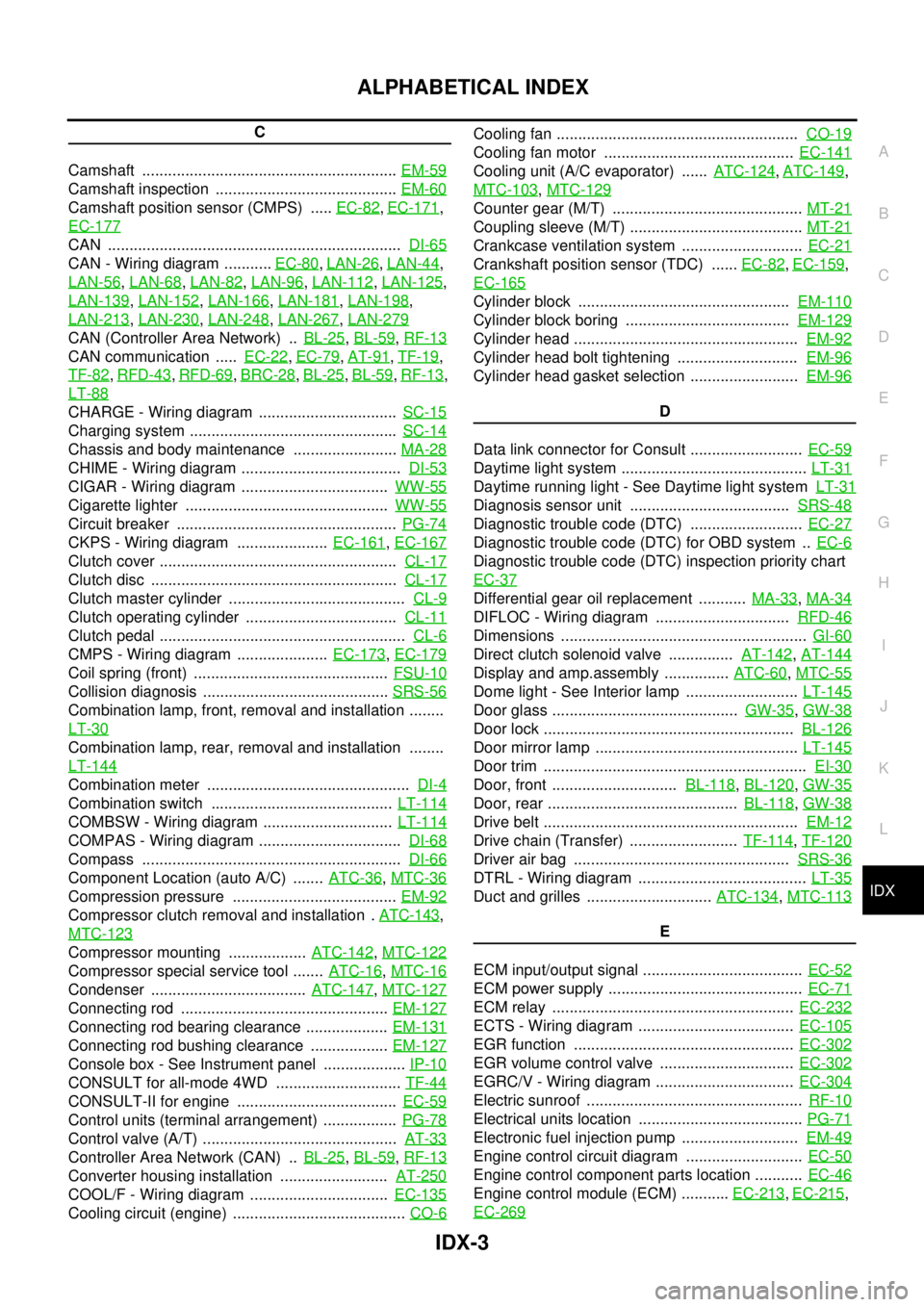
ALPHABETICAL INDEX
C
Camshaft ...........................................................EM-59
Camshaft inspection ..........................................EM-60
Camshaft position sensor (CMPS) .....EC-82,EC-171,
EC-177
CAN ....................................................................DI-65
CAN - Wiring diagram ...........EC-80,LAN-26,LAN-44,
LAN-56
,LAN-68,LAN-82,LAN-96,LAN-112,LAN-125,
LAN-139
,LAN-152,LAN-166,LAN-181,LAN-198,
LAN-213
,LAN-230,LAN-248,LAN-267,LAN-279
CAN (Controller Area Network) ..BL-25,BL-59,RF-13
CAN communication .....EC-22,EC-79,AT-91,TF-19,
TF-82
,RFD-43,RFD-69,BRC-28,BL-25,BL-59,RF-13,
LT-88
CHARGE - Wiring diagram ................................SC-15
Charging system ................................................SC-14
Chassis and body maintenance ........................MA-28
CHIME - Wiring diagram .....................................DI-53
CIGAR - Wiring diagram ..................................WW-55
Cigarette lighter ...............................................WW-55
Circuit breaker ...................................................PG-74
CKPS - Wiring diagram .....................EC-161,EC-167
Clutch cover .......................................................CL-17
Clutch disc .........................................................CL-17
Clutch master cylinder .........................................CL-9
Clutch operating cylinder ...................................CL-11
Clutch pedal .........................................................CL-6
CMPS - Wiring diagram .....................EC-173,EC-179
Coil spring (front) .............................................FSU-10
Collision diagnosis ...........................................SRS-56
Combination lamp, front, removal and installation ........
LT-30
Combination lamp, rear, removal and installation ........
LT-144
Combination meter ...............................................DI-4
Combination switch ..........................................LT-114
COMBSW - Wiring diagram ..............................LT-114
COMPAS - Wiring diagram .................................DI-68
Compass ............................................................DI-66
Component Location (auto A/C) .......ATC-36,MTC-36
Compression pressure ......................................EM-92
Compressor clutch removal and installation .ATC-143,
MTC-123
Compressor mounting ..................ATC-142,MTC-122
Compressor special service tool .......ATC-16,MTC-16
Condenser ....................................ATC-147,MTC-127
Connecting rod ................................................EM-127
Connecting rod bearing clearance ...................EM-131
Connecting rod bushing clearance ..................EM-127
Console box - See Instrument panel ...................IP-10
CONSULT for all-mode 4WD .............................TF-44
CONSULT-II for engine .....................................EC-59
Control units (terminal arrangement) .................PG-78
Control valve (A/T) .............................................AT-33
Controller Area Network (CAN) ..BL-25,BL-59,RF-13
Converter housing installation .........................AT-250
COOL/F - Wiring diagram ................................EC-135
Cooling circuit (engine) ........................................CO-6
Cooling fan ........................................................CO-19
Cooling fan motor ............................................EC-141
Cooling unit (A/C evaporator) ......ATC-124,ATC-149,
MTC-103
,MTC-129
Counter gear (M/T) ............................................MT-21
Coupling sleeve (M/T) ........................................MT-21
Crankcase ventilation system ............................EC-21
Crankshaft position sensor (TDC) ......EC-82,EC-159,
EC-165
Cylinder block .................................................EM-110
Cylinder block boring ......................................EM-129
Cylinder head ....................................................EM-92
Cylinder head bolt tightening ............................EM-96
Cylinder head gasket selection .........................EM-96
D
Data link connector for Consult ..........................EC-59
Daytime light system ...........................................LT-31
Daytime running light - See Daytime light systemLT-31
Diagnosis sensor unit .....................................SRS-48
Diagnostic trouble code (DTC) ..........................EC-27
Diagnostic trouble code (DTC) for OBD system ..EC-6
Diagnostic trouble code (DTC) inspection priority chart
EC-37
Differential gear oil replacement ...........MA-33,MA-34
DIFLOC - Wiring diagram ...............................RFD-46
Dimensions .........................................................GI-60
Direct clutch solenoid valve ...............AT-142,AT-144
Display and amp.assembly ...............ATC-60,MTC-55
Dome light - See Interior lamp ..........................LT-145
Door glass ...........................................GW-35,GW-38
Door lock ..........................................................BL-126
Door mirror lamp ...............................................LT-145
Door trim .............................................................EI-30
Door, front .............................BL-118,BL-120,GW-35
Door, rear ............................................BL-118,GW-38
Drive belt ...........................................................EM-12
Drive chain (Transfer) .........................TF-114,TF-120
Driver air bag ..................................................SRS-36
DTRL - Wiring diagram .......................................LT-35
Duct and grilles .............................ATC-134,MTC-113
E
ECM input/output signal .....................................EC-52
ECM power supply .............................................EC-71
ECM relay ........................................................EC-232
ECTS - Wiring diagram ....................................EC-105
EGR function ...................................................EC-302
EGR volume control valve ...............................EC-302
EGRC/V - Wiring diagram ................................EC-304
Electric sunroof ..................................................RF-10
Electrical units location ......................................PG-71
Electronic fuel injection pump ...........................EM-49
Engine control circuit diagram ...........................EC-50
Engine control component parts location ...........EC-46
Engine control module (ECM) ...........EC-213,EC-215,
EC-269
Page 1778 of 3171
LAN-1
LAN SYSTEM
K ELECTRICAL
CONTENTS
C
D
E
F
G
H
I
J
L
M
SECTIONLAN
A
B
LAN
LAN SYSTEM
CAN
PRECAUTIONS .......................................................... 3
Precautions for Supplemental Restraint System
(SRS)“AIRBAG”and“SEATBELTPRE-TEN-
SIONER” .................................................................. 3
Precautions When Using CONSULT-II ..................... 3
CHECK POINTS FOR USING CONSULT-II ......... 3
Precautions For Trouble Diagnosis .......................... 3
CAN SYSTEM ....................................................... 3
Precautions For Harness Repair .............................. 3
CAN SYSTEM ....................................................... 3
TROUBLE DIAGNOSES WORK FLOW .................... 5
When Displaying CAN Communication System
Errors ....................................................................... 5
WHEN A MALFUNCTION IS DETECTED BY
CAN COMMUNICATION SYSTEM ....................... 5
WHEN A MALFUNCTION IS DETECTED
EXCEPT CAN COMMUNICATION SYSTEM ........ 5
TROUBLE DIAGNOSIS FLOW CHART ............... 6
Diagnosis Procedure ................................................ 7
SELECTING CAN SYSTEM TYPE (HOW TO
USE SPECIFICATION TABLE) ............................. 7
ACQUISITION OF DATA BY CONSULT-II ............ 8
HOW TO USE CHECK SHEET TABLE ................ 9
CAN Diagnostic Support Monitor ........................... 15
DESCRIPTION OF “CAN DIAG SUPPORT
MNTR” SCREEN FOR ECM ............................... 15
DESCRIPTION OF “CAN DIAG SUPPORT
MNTR” SCREEN FOR TCM ............................... 16
DESCRIPTION OF “CAN DIAG SUPPORT
MNTR” SCREEN FOR NAVI CONTROL UNIT ... 17
DESCRIPTION OF “CAN DIAG SUPPORT
MNTR” SCREEN FOR DIFFERENTIAL LOCK
CONTROL UNIT ................................................. 18
DESCRIPTION OF “CAN DIAG SUPPORT
MNTR” SCREEN FOR FRONT AIR CONTROL... 19
DESCRIPTION OF “CAN DIAG SUPPORT
MNTR” SCREEN FOR BCM ............................... 20
DESCRIPTION OF “CAN DIAG SUPPORT
MNTR” SCREEN FOR TRANSFER CONTROLUNIT .................................................................... 21
DESCRIPTION OF “CAN DIAG SUPPORT
MNTR” SCREEN FOR ABS ACTUATOR AND
ELECTRIC UNIT (CONTROL UNIT) ................... 21
DESCRIPTION OF “CAN DIAG SUPPORT
MNTR” SCREEN FOR IPDM E/R ....................... 22
CAN COMMUNICATION ........................................... 23
System Description ................................................. 23
Component Parts and Harness Connector Location... 23
LHD MODELS ..................................................... 23
RHD MODELS .................................................... 24
Schematic ............................................................... 25
Wiring Diagram — CAN — ..................................... 26
CAN Communication Unit ....................................... 30
TYPE 1/ TYPE 2/ TYPE 3 ................................... 32
TYPE 4/ TYPE 5 .................................................. 34
TYPE 6/ TYPE 7/ TYPE 8/ TYPE 9/ TYPE 10/
TYPE 11/ TYPE 16/ TYPE 17 .............................. 36
TYPE 12/ TYPE 13/ TYPE 14/ TYPE 15 ............. 40
CAN SYSTEM (TYPE 1) ........................................... 44
Component Parts and Harness Connector Location... 44
Schematic ............................................................... 44
Wiring Diagram — CAN — ..................................... 44
Check Sheet ........................................................... 45
CHECK SHEET RESULTS (EXAMPLE) ............. 47
CAN SYSTEM (TYPE 2) ........................................... 56
Component Parts and Harness Connector Location... 56
Schematic ............................................................... 56
Wiring Diagram — CAN — ..................................... 56
Check Sheet ........................................................... 57
CHECK SHEET RESULTS (EXAMPLE) ............. 59
CAN SYSTEM (TYPE 3) ........................................... 68
Component Parts and Harness Connector Location... 68
Schematic ............................................................... 68
Wiring Diagram — CAN — ..................................... 68
Check Sheet ........................................................... 69
CHECK SHEET RESULTS (EXAMPLE) ............. 71
CAN SYSTEM (TYPE 4) ........................................... 82
Component Parts and Harness Connector Location... 82
Schematic ............................................................... 82
Page 1779 of 3171

LAN-2
Wiring Diagram — CAN — ..................................... 82
Check Sheet ........................................................... 83
CHECK SHEET RESULTS (EXAMPLE) ............. 85
CAN SYSTEM (TYPE 5) ........................................... 96
Component Parts and Harness Connector Location... 96
Schematic ............................................................... 96
Wiring Diagram — CAN — ..................................... 96
Check Sheet ........................................................... 97
CHECK SHEET RESULTS (EXAMPLE) ............. 99
CAN SYSTEM (TYPE 6) .........................................112
Component Parts and Harness Connector Location.112
Schematic .............................................................112
Wiring Diagram — CAN — ...................................112
Check Sheet .........................................................113
CHECK SHEET RESULTS (EXAMPLE) ...........115
CAN SYSTEM (TYPE 7) .........................................125
Component Parts and Harness Connector Location.125
Schematic .............................................................125
Wiring Diagram — CAN — ...................................125
Check Sheet .........................................................126
CHECK SHEET RESULTS (EXAMPLE) ...........128
CAN SYSTEM (TYPE 8) .........................................139
Component Parts and Harness Connector Location.139
Schematic .............................................................139
Wiring Diagram — CAN — ...................................139
Check Sheet .........................................................140
CHECK SHEET RESULTS (EXAMPLE) ...........142
CAN SYSTEM (TYPE 9) .........................................152
Component Parts and Harness Connector Location.152
Schematic .............................................................152
Wiring Diagram — CAN — ...................................152
Check Sheet .........................................................153
CHECK SHEET RESULTS (EXAMPLE) ...........155
CAN SYSTEM (TYPE 10) .......................................166
Component Parts and Harness Connector Location.166
Schematic .............................................................166
Wiring Diagram — CAN — ...................................166
Check Sheet .........................................................167
CHECK SHEET RESULTS (EXAMPLE) ...........169
CAN SYSTEM (TYPE 11) ........................................181
Component Parts and Harness Connector Location.181
Schematic .............................................................181
Wiring Diagram — CAN — ...................................181
Check Sheet .........................................................182
CHECK SHEET RESULTS (EXAMPLE) ...........185
CAN SYSTEM (TYPE 12) .......................................198
Component Parts and Harness Connector Location.198
Schematic .............................................................198
Wiring Diagram — CAN — ...................................198
Check Sheet .........................................................199
CHECK SHEET RESULTS (EXAMPLE) ...........201
CAN SYSTEM (TYPE 13) .......................................213
Component Parts and Harness Connector Location.213Schematic .............................................................213
Wiring Diagram — CAN — ...................................213
Check Sheet .........................................................214
CHECK SHEET RESULTS (EXAMPLE) ............217
CAN SYSTEM (TYPE 14) ........................................230
Component Parts and Harness Connector Location.230
Schematic .............................................................230
Wiring Diagram — CAN — ...................................230
Check Sheet .........................................................231
CHECK SHEET RESULTS (EXAMPLE) ............234
CAN SYSTEM (TYPE 15) ........................................248
Component Parts and Harness Connector Location.248
Schematic .............................................................248
Wiring Diagram — CAN — ...................................248
Check Sheet .........................................................249
CHECK SHEET RESULTS (EXAMPLE) ............252
CAN SYSTEM (TYPE 16) ........................................267
Component Parts and Harness Connector Location.267
Schematic .............................................................267
Wiring Diagram — CAN — ...................................267
Check Sheet .........................................................268
CHECK SHEET RESULTS (EXAMPLE) ............270
CAN SYSTEM (TYPE 17) ........................................279
Component Parts and Harness Connector Location.279
Schematic .............................................................279
Wiring Diagram — CAN — ...................................279
Check Sheet .........................................................280
CHECK SHEET RESULTS (EXAMPLE) ............282
TROUBLE DIAGNOSIS FOR SYSTEM ..................292
Inspection Between TCM and Data Link Connector
Circuit ....................................................................292
Inspection Between TCM and NAVI Control Unit Cir-
cuit ........................................................................293
Inspection Between NAVI Control Unit and Data
Link Connector Circuit ...........................................295
Inspection Between Data Link Connector and ABS
Actuator and Electric Unit (Control Unit) Circuit ....296
ECM Circuit Inspection for M/T Models ................297
ECM Circuit Inspection for A/T Models .................298
TCM Circuit Inspection ..........................................298
NAVI Control Unit Circuit Inspection .....................299
Differential Lock Control Unit Circuit Inspection ....299
Front Air Control Circuit Inspection .......................300
Data Link Connector Circuit Inspection .................300
BCM Circuit Inspection .........................................301
Combination Meter Circuit Inspection ...................301
Transfer Control Unit Circuit Inspection ................302
ABS Actuator and Electric Unit (Control Unit) Circuit
Inspection ..............................................................302
IPDM E/R Circuit Inspection .................................303
CAN Communication Circuit Inspection ................303
IPDM E/R Ignition Relay Circuit Inspection ...........304
Page 1795 of 3171
![NISSAN NAVARA 2005 Repair Workshop Manual LAN-18
[CAN]
TROUBLE DIAGNOSES WORK FLOW
DESCRIPTION OF “CAN DIAG SUPPORT MNTR” SCREEN
FOR DIFFERENTIAL LOCK CONTROL UNIT
Display Results (Present)
lOK: Normal
lNG: Malfunction
lUNKWN: The diagnos NISSAN NAVARA 2005 Repair Workshop Manual LAN-18
[CAN]
TROUBLE DIAGNOSES WORK FLOW
DESCRIPTION OF “CAN DIAG SUPPORT MNTR” SCREEN
FOR DIFFERENTIAL LOCK CONTROL UNIT
Display Results (Present)
lOK: Normal
lNG: Malfunction
lUNKWN: The diagnos](/manual-img/5/57362/w960_57362-1794.png)
LAN-18
[CAN]
TROUBLE DIAGNOSES WORK FLOW
DESCRIPTION OF “CAN DIAG SUPPORT MNTR” SCREEN
FOR DIFFERENTIAL LOCK CONTROL UNIT
Display Results (Present)
lOK: Normal
lNG: Malfunction
lUNKWN: The diagnosed unit does not transmit or receive the applicable data normally.
PKIB7196E
“SELECT SYSTEM”
screen“CAN DIAG SUPPORT
MNTR” screenDescription Present
DIFF LOCKINITIAL DIAG Make sure that microcomputer in ECU works normally. OK/NG
TRANSMIT DIAG Make sure of normal transmission. OK/UNKWN
ECM Make sure of normal reception from ECM. OK/UNKWN
VDC/TCS/ABSMake sure of normal reception from ABS actuator and electric unit
(control unit).OK/UNKWN
AWD/4WD Make sure of normal reception from transfer control unit. OK/UNKWN