2005 NISSAN NAVARA instrument cluster
[x] Cancel search: instrument clusterPage 1345 of 3171
SQUEAK AND RATTLE TROUBLE DIAGNOSES
EI-7
C
D
E
F
G
H
J
K
L
MA
B
EI
DUPLICATE THE NOISE AND TEST DRIVE
If possible, drive the vehicle with the customer until the noise is duplicated. Note any additional information on
the Diagnostic Worksheet regarding the conditions or location of the noise. This information can be used to
duplicate the same conditions when you confirm the repair.
If the noise can be duplicated easily during the test drive, to help identify the source of the noise, try to dupli-
cate the noise with the vehicle stopped by doing one or all of the following:
1) Close a door.
2) Tap or push/pull around the area where the noise appears to be coming from.
3) Rev the engine.
4) Use a floor jack to recreate vehicle “twist”.
5) At idle, apply engine load (electrical load, half-clutch on M/T model, drive position on A/T model).
6) Raisethevehicleonahoistandhitatirewitharubberhammer.
lDrive the vehicle and attempt to duplicate the conditions the customer states exist when the noise occurs.
lIf it is difficult to duplicate the noise, drive the vehicle slowly on an undulating or rough road to stress the
vehicle body.
CHECK RELATED SERVICE BULLETINS
After verifying the customer concern or symptom, check ASIST for Technical Service Bulletins (TSBs) related
to that concern or symptom.
If a TSB relates to the symptom, follow the procedure to repair the noise.
LOCATE THE NOISE AND IDENTIFY THE ROOT CAUSE
1. Narrow down the noise to a general area.To help pinpoint the source of the noise, use a listening tool
(Engine Ear and mechanic's stethoscope).
2. Narrow down the noise to a more specific area and identify the cause of the noise by:
lremoving the components in the area that you suspect the noise is coming from.
Do not use too much force when removing clips and fasteners, otherwise clips and fasteners can be bro-
ken or lost during the repair, resulting in the creation of new noise.
ltapping or pushing/pulling the component that you suspect is causing the noise.
Do not tap or push/pull the component with excessive force, otherwise the noise will be eliminated only
temporarily.
lfeeling for a vibration with your hand by touching the component(s) that you suspect is (are) causing the
noise.
lplacing a piece of paper between components that you suspect are causing the noise.
llooking for loose components and contact marks.
Refer toEI-7, "
Generic Squeak and Rattle Troubleshooting".
REPAIR THE CAUSE
lIf the cause is a loose component, tighten the component securely.
lIf the cause is insufficient clearance between components:
–separate components by repositioning or loosening and retightening the component, if possible.
–insulate components with a suitable insulator such as urethane pads, foam blocks, felt cloth tape or ure-
thane tape.
CAUTION:
Do not use excessive force as many components are constructed of plastic and may be damaged.
Always check with the Parts Department for the latest parts information.
CONFIRM THE REPAIR
Confirm that the cause of a noise is repaired by test driving the vehicle. Operate the vehicle under the same
conditions as when the noise originally occurred. Refer to the notes on the Diagnostic Worksheet.
Generic Squeak and Rattle TroubleshootingEIS00DY6
Refer to Table of Contents for specific component removal and installation information.
INSTRUMENT PANEL
Most incidents are caused by contact and movement between:
1. The cluster lid A and instrument panel
2. Acrylic lens and combination meter housing
Page 1346 of 3171

EI-8
SQUEAK AND RATTLE TROUBLE DIAGNOSES
3. Instrument panel to front pillar garnish
4. Instrument panel to windshield
5. Instrument panel mounting pins
6. Wiring harnesses behind the combination meter
7. A/C defroster duct and duct joint
These incidents can usually be located by tapping or moving the components to duplicate the noise or by
pressing on the components while driving to stop the noise. Most of these incidents can be repaired by apply-
ing felt cloth tape or silicone spray (in hard to reach areas). Urethane pads can be used to insulate wiring har-
ness.
CAUTION:
Do not use silicone spray to isolate a squeak or rattle. If you saturate the area with silicone, you will
not be able to recheck the repair.
CENTER CONSOLE
Components to pay attention to include:
1. Shifter assembly cover to finisher
2. A/C control unit and cluster lid C
3. Wiring harnesses behind audio and A/C control unit
The instrument panel repair and isolation procedures also apply to the center console.
DOORS
Pay attention to the:
1. Finisher and inner panel making a slapping noise
2. Inside handle escutcheon to door finisher
3. Wiring harnesses tapping
4. Door striker out of alignment causing a popping noise on starts and stops
Tapping or moving the components or pressing on them while driving to duplicate the conditions can isolate
many of these incidents.
TRUNK
Trunk noises are often caused by a loose jack or loose items put into the trunk by the owner.
In addition look for:
1. Trunk lid bumpers out of adjustment
2. Trunk lid striker out of adjustment
3. The trunk lid torsion bars knocking together
4. A loose license plate or bracket
Most of these incidents can be repaired by adjusting, securing or insulating the item(s) or component(s) caus-
ing the noise.
SUNROOF/HEADLINING
Noises in the sunroof/headlining area can often be traced to one of the following:
1. Sunroof lid, rail, linkage or seals making a rattle or light knocking noise
2. Sun visor shaft shaking in the holder
3. Front or rear windshield touching headliner and squeaking
Again, pressing on the components to stop the noise while duplicating the conditions can isolate most of these
incidents. Repairs usually consist of insulating with felt cloth tape.
OVERHEAD CONSOLE (FRONT AND REAR)
Overhead console noises are often caused by the console panel clips not being engaged correctly. Most of
these incidents are repaired by pushing up on the console at the clip locations until the clips engage.
In addition look for:
1. Loose harness or harness connectors.
2. Front console map/reading lamp lens loose.
3. Loose screws at console attachment points.
Page 1693 of 3171
SQUEAK AND RATTLE TROUBLE DIAGNOSES
GW-7
C
D
E
F
G
H
J
K
L
MA
B
GW
FELT CLOTHTAPE
Used to insulate where movement does not occur. Ideal for instrument panel applications.
68370-4B000: 15´25 mm (0.59´0.98 in) pad/68239-13E00: 5 mm (0.20 in) wide tape roll
The following materials, not available through NISSAN Parts Department, can also be used to repair squeaks
and rattles.
UHMW(TEFLON) TAPE
Insulates where slight movement is present. Ideal for instrument panel applications.
SILICONE GREASE
Used in place of UHMW tape that will be visible or not fit.
Note: Will only last a few months.
SILICONE SPRAY
Use when grease cannot be applied.
DUCT TAPE
Usetoeliminatemovement.
CONFIRM THE REPAIR
Confirm that the cause of a noise is repaired by test driving the vehicle. Operate the vehicle under the same
conditions as when the noise originally occurred. Refer to the notes on the Diagnostic Worksheet.
Generic Squeak and Rattle TroubleshootingEIS00C03
Refer to Table of Contents for specific component removal and installation information.
INSTRUMENT PANEL
Most incidents are caused by contact and movement between:
1. Cluster lid A and instrument panel
2. Acrylic lens and combination meter housing
3. Instrument panel to front pillar garnish
4. Instrument panel to windshield
5. Instrument panel mounting pins
6. Wiring harnesses behind the combination meter
7. A/C defroster duct and duct joint
These incidents can usually be located by tapping or moving the components to duplicate the noise or by
pressing on the components while driving to stop the noise. Most of these incidents can be repaired by
applying felt cloth tape or silicon spray (in hard to reach areas). Urethane pads can be used to insulate
wiring harness.
CAUTION:
Do not use silicone spray to isolate a squeak or rattle. If you saturate the area with silicone, you
will not be able to recheck the repair.
CENTER CONSOLE
Components to pay attention to include:
1. Shifter assembly cover to finisher
2. A/C control unit and cluster lid C
3. Wiring harnesses behind audio and A/C control unit
The instrument panel repair and isolation procedures also apply to the center console.
DOORS
Pay attention to the:
1. Finisher and inner panel making a slapping noise
2. Inside handle escutcheon to door finisher
3. Wiring harnesses tapping
4. Door striker out of alignment causing a popping noise on starts and stops
Tapping or moving the components or pressing on them while driving to duplicate the conditions can isolate
many of these incidents. You can usually insulate the areas with felt cloth tape or insulator foam blocks to
repair the noise.
Page 1760 of 3171

IP-1
INSTRUMENT PANEL
IBODY
CONTENTS
C
D
E
F
G
H
J
K
L
M
SECTIONIP
A
B
IP
INSTRUMENT PANEL
PRECAUTIONS .......................................................... 2
Precautions for Supplemental Restraint System
(SRS)“AIRBAG”and“SEATBELTPRE-TEN-
SIONER” .................................................................. 2
Precautions for SRS “AIR BAG” and “SEAT BELT
PRE-TENSIONER” Service ..................................... 2
PREPARATION ........................................................... 3
Commercial Service Tools ........................................ 3
SQUEAK AND RATTLE TROUBLE DIAGNOSES..... 4
Work Flow ................................................................ 4
CUSTOMER INTERVIEW ..................................... 4
DUPLICATE THE NOISE AND TEST DRIVE ....... 5
CHECK RELATED SERVICE BULLETINS ........... 5
LOCATE THE NOISE AND IDENTIFY THE
ROOT CAUSE ...................................................... 5
REPAIR THE CAUSE ........................................... 5
CONFIRM THE REPAIR ....................................... 5
Generic Squeak and Rattle Troubleshooting ........... 6
INSTRUMENT PANEL .......................................... 6
CENTER CONSOLE ............................................. 6
DOORS ................................................................. 6TRUNK .................................................................. 6
SUNROOF/HEADLINING ..................................... 7
OVERHEAD CONSOLE (FRONT AND REAR)..... 7
SEATS ................................................................... 7
UNDERHOOD ....................................................... 7
Diagnostic Worksheet ............................................... 8
INSTRUMENT PANEL ASSEMBLY ......................... 10
Removal and Installation ........................................ 10
INSTRUMENT PANEL ........................................ 10
CLUSTER LID C ................................................. 11
CLUSTER LID D ................................................. 12
LOWER INSTRUMENT PANEL LH ..................... 13
COMBINATION METER ...................................... 13
A/T CONTROL FINISHER (A/T) .......................... 14
CONSOLE BOOT M/T ........................................ 14
LOWER INSTRUMENT PANEL RH AND GLOVE
BOX ..................................................................... 15
CENTER CONSOLE ........................................... 16
Disassembly and Assembly .................................... 17
CENTER CONSOLE ........................................... 17
Page 1765 of 3171

IP-6
SQUEAK AND RATTLE TROUBLE DIAGNOSES
Generic Squeak and Rattle Troubleshooting
EIS00DYX
Refer to Table of Contents for specific component removal and installation information.
INSTRUMENT PANEL
Most incidents are caused by contact and movement between:
1. The cluster lid A and instrument panel
2. Acrylic lens and combination meter housing
3. Instrument panel to front pillar garnish
4. Instrument panel to windshield
5. Instrument panel mounting pins
6. Wiring harnesses behind the combination meter
7. A/C defroster duct and duct joint
These incidents can usually be located by tapping or moving the components to duplicate the noise or by
pressing on the components while driving to stop the noise. Most of these incidents can be repaired by apply-
ing felt cloth tape or silicone spray (in hard to reach areas). Urethane pads can be used to insulate wiring har-
ness.
CAUTION:
Do not use silicone spray to isolate a squeak or rattle. If you saturate the area with silicone, you will
not be able to recheck the repair.
CENTER CONSOLE
Components to pay attention to include:
1. Shifter assembly cover to finisher
2. A/C control unit and cluster lid C
3. Wiring harnesses behind audio and A/C control unit
The instrument panel repair and isolation procedures also apply to the center console.
DOORS
Pay attention to the:
1. Finisher and inner panel making a slapping noise
2. Inside handle escutcheon to door finisher
3. Wiring harnesses tapping
4. Door striker out of alignment causing a popping noise on starts and stops
Tapping or moving the components or pressing on them while driving to duplicate the conditions can isolate
many of these incidents. You can usually insulate the areas with felt cloth tape or insulator foam blocks to
repair the noise.
TRUNK
Trunk noises are often caused by a loose jack or loose items put into the trunk by the owner.
In addition look for:
1. Trunk lid bumpers out of adjustment
2. Trunk lid striker out of adjustment
3. The trunk lid torsion bars knocking together
4. A loose license plate or bracket
Most of these incidents can be repaired by adjusting, securing or insulating the item(s) or component(s) caus-
ing the noise.
Page 1769 of 3171
IP-10
INSTRUMENT PANEL ASSEMBLY
INSTRUMENT PANEL ASSEMBLY
PFP:68200
Removal and InstallationEIS00DYZ
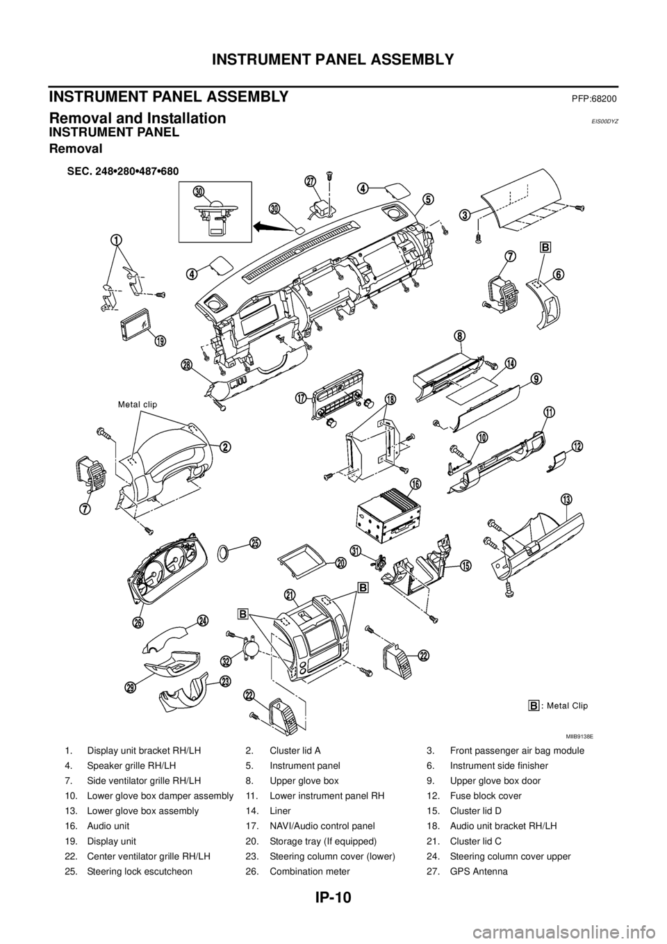
INSTRUMENT PANEL
Removal
1. Display unit bracket RH/LH 2. Cluster lid A 3. Front passenger air bag module
4. Speaker grille RH/LH 5. Instrument panel 6. Instrument side finisher
7. Side ventilator grille RH/LH 8. Upper glove box 9. Upper glove box door
10. Lower glove box damper assembly 11. Lower instrument panel RH 12. Fuse block cover
13. Lower glove box assembly 14. Liner 15. Cluster lid D
16. Audio unit 17. NAVI/Audio control panel 18. Audio unit bracket RH/LH
19. Display unit 20. Storage tray (If equipped) 21. Cluster lid C
22. Center ventilator grille RH/LH 23. Steering column cover (lower) 24. Steering column cover upper
25. Steering lock escutcheon 26. Combination meter 27. GPS Antenna
MIIB9138E
Page 1770 of 3171
INSTRUMENT PANEL ASSEMBLY
IP-11
C
D
E
F
G
H
J
K
L
MA
B
IP
1. Remove the center console. Refer toIP-16, "CENTER CONSOLE".
2. Remove the steering column covers. Refer toPS-11, "
STEERING COLUMN".
3. Remove the combination meter. Refer toIP-13, "
COMBINATION METER".
4. Release then disconnect the optical sensor harness.
5. Remove the LH and RH front pillar upper garnish.
6. Remove cluster lid C.
7. Remove screws fixing CD Audio bracket, then remove CD Audio unit assembly. (If equipped). Refer toAV-
73, "Auido Unit (1CD Player Type)".
8. Remove cluster lid D. Refer toIP-12, "
CLUSTER LID D".
9. Remove screws fixing GPS Antenna, then move GPS Antenna.
10. Remove screws fixing display unit bracket, then remove display unit assembly. (If equipped)
11. Remove front passenger air bag module.
12. Remove instrument panel.
lDisconnect harnesses to instrument panel speakers LH and RH and remove speakers.
lDisconnect all remaining harnesses.
lRemove the passenger air bag module. Refer toSRS-40, "FRONT PASSENGER AIR BAG MODULE".
Installation
Installation is in the reverse order of removal.
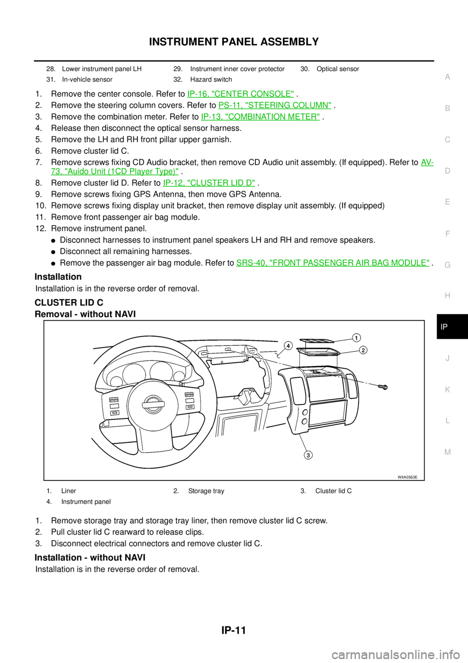
CLUSTER LID C
Removal - without NAVI
1. Remove storage tray and storage tray liner, then remove cluster lid C screw.
2. Pull cluster lid C rearward to release clips.
3. Disconnect electrical connectors and remove cluster lid C.
Installation - without NAVI
Installation is in the reverse order of removal.
28. Lower instrument panel LH 29. Instrument inner cover protector 30. Optical sensor
31. In-vehicle sensor 32. Hazard switch
WIIA0563E
1. Liner 2. Storage tray 3. Cluster lid C
4. Instrument panel
Page 1771 of 3171
IP-12
INSTRUMENT PANEL ASSEMBLY
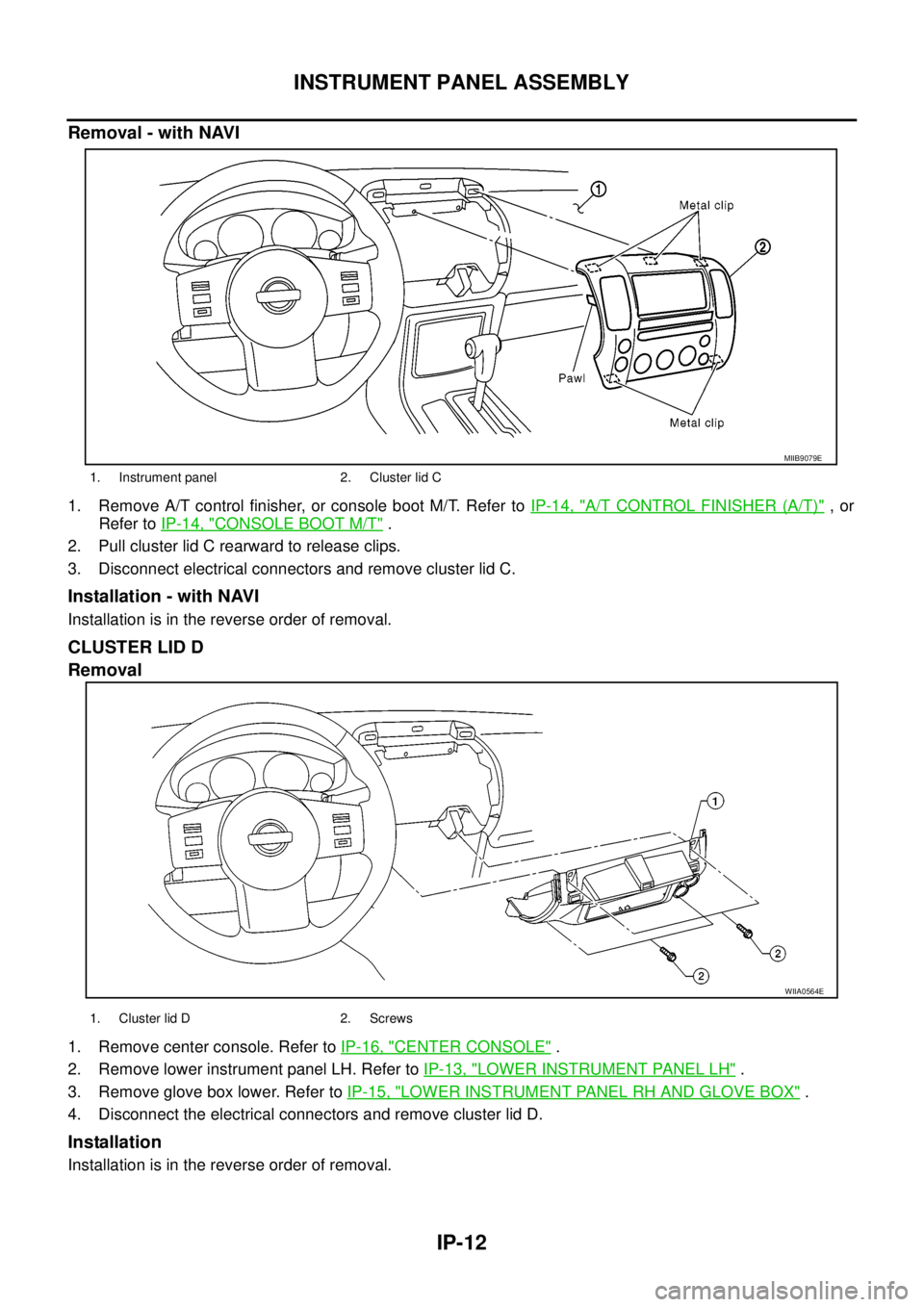
Removal - with NAVI
1. Remove A/T control finisher, or console boot M/T. Refer toIP-14, "A/T CONTROL FINISHER (A/T)",or
Refer toIP-14, "
CONSOLE BOOT M/T".
2. Pull cluster lid C rearward to release clips.
3. Disconnect electrical connectors and remove cluster lid C.
Installation - with NAVI
Installation is in the reverse order of removal.
CLUSTER LID D
Removal
1. Remove center console. Refer toIP-16, "CENTER CONSOLE".
2. Remove lower instrument panel LH. Refer toIP-13, "
LOWER INSTRUMENT PANEL LH".
3. Remove glove box lower. Refer toIP-15, "
LOWER INSTRUMENT PANEL RH AND GLOVE BOX".
4. Disconnect the electrical connectors and remove cluster lid D.
Installation
Installation is in the reverse order of removal.
1. Instrument panel 2. Cluster lid C
MIIB9079E
WIIA0564E
1. Cluster lid D 2. Screws