Page 1403 of 3171
INTAKE MANIFOLD
EM-21
C
D
E
F
G
H
I
J
K
L
MA
EM
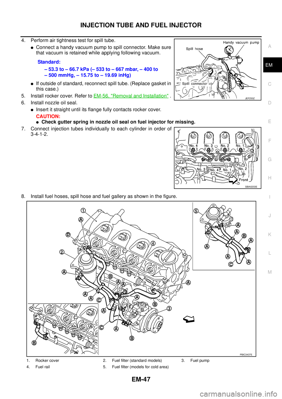
lRefer toGI-10, "Components"for symbol marks except in the above.
Removal and InstallationEBS01EJF
REMOVAL
WARNING:
To avoid the danger of being scalded, do not drain engine coolant when engine is hot.
1. Drain engine coolant. Refer toCO-7, "
Changing Engine Coolant".
2. Remove engine cover (1).
CAUTION:
Be careful not to damage engine cover surface.
3. Disconnect air inlet hose from throttle chamber. Refer toEM-18, "
CHARGE AIR COOLER".
4. Remove fuel filter. Refer toFL-4, "
FUEL FILTER".
5. Remove oil level gauge guide. Refer toEM-36, "
OIL PAN AND OIL STRAINER".
6. Remove fuel hoses and fuel gallery. Refer toEM-44, "
INJECTION TUBE AND FUEL INJECTOR".
lTo prevent fuel from flowing out, plug the opening of the hose with plug after disconnection.
CAUTION:
Be careful not to spill fuel in the engine component.
lAdd marks as necessary for easier installation.
7. Remove vacuum galleries and vacuum hoses.
lAdd marks as necessary for easier installation.
8. Disconnect EGR volume control valve water hoses and wiring harness.
9. Disconnect heater feed hose, water hoses, and remove heater feed pipe.
10. Remove EGR cooler (A/T models) or EGR tube (M/T models).
11. Remove injection tube center. Refer toEM-44, "
Removal and Installation".
CAUTION:
Be careful not to spill fuel in the engine component.
12. Remove water pipe.
1. Vacuum hose 2. Vacuum gallery 3. Vacuum hose
4. Bracket 5. Bracket 6. Gasket
7. Bracket 8. Intake manifold 9. Water hose
10. Heater feed pipe (M/T models) 11. O-ring 12. Vacuum hose
13. Vacuum gallery 14. Vacuum hose 15. Gasket
16. Throttle chamber 17. Gasket 18. Gasket
19. EGR passage 20. Gasket 21. Bracket
22. EGR volume control valve 23. Vacuum gallery 24. Bracket
25. Washer 26. Gasket 27. EGR tube (M/T models)
28. Water hose 29. Water hose 30. Clip (A/T models)
31. Water hose (A/T models) 32. Heater feed pipe (A/T models) 33. Water hose (A/T models)
34. EGR cooler (A/T models) 35. Gasket (A/T models) 36. EGR tube (A/T models)
37. Bracket (A/T models)
C. To heater return pipe E. To cylinder head F. To water outlet
G. To exhaust manifold H. To air inlet hose
Vehicle front
PBIC3409E
Page 1426 of 3171
EM-44
INJECTION TUBE AND FUEL INJECTOR
INJECTION TUBE AND FUEL INJECTOR
PFP:00018
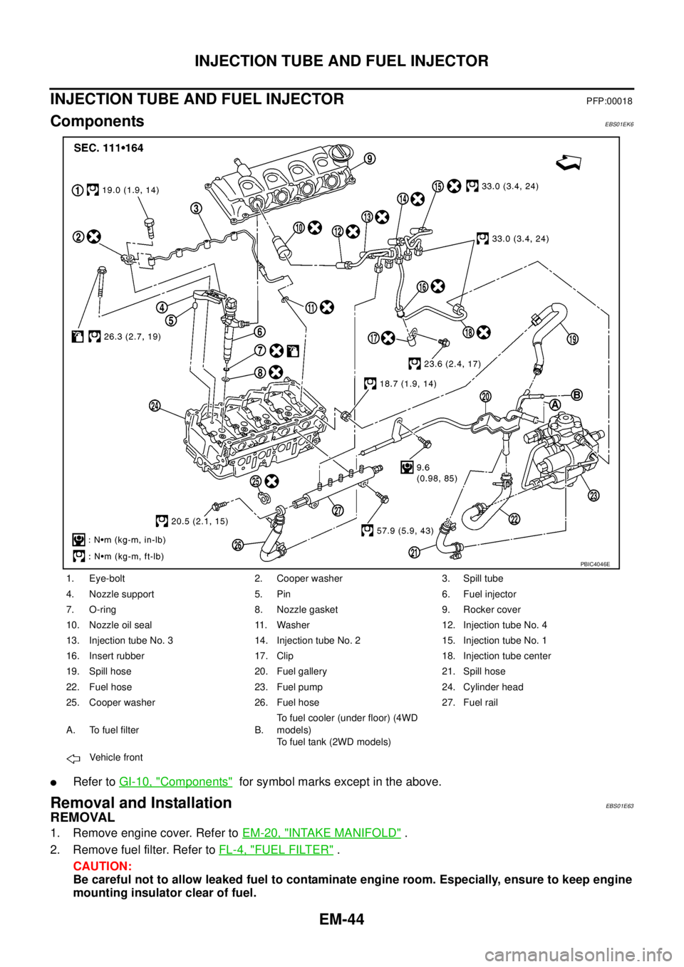
ComponentsEBS01EK6
lRefer toGI-10, "Components"for symbol marks except in the above.
Removal and InstallationEBS01E63
REMOVAL
1. Remove engine cover. Refer toEM-20, "INTAKE MANIFOLD".
2. Remove fuel filter. Refer toFL-4, "
FUEL FILTER".
CAUTION:
Be careful not to allow leaked fuel to contaminate engine room. Especially, ensure to keep engine
mounting insulator clear of fuel.
1. Eye-bolt 2. Cooper washer 3. Spill tube
4. Nozzle support 5. Pin 6. Fuel injector
7. O-ring 8. Nozzle gasket 9. Rocker cover
10. Nozzle oil seal 11. Washer 12. Injection tube No. 4
13. Injection tube No. 3 14. Injection tube No. 2 15. Injection tube No. 1
16. Insert rubber 17. Clip 18. Injection tube center
19. Spill hose 20. Fuel gallery 21. Spill hose
22. Fuel hose 23. Fuel pump 24. Cylinder head
25. Cooper washer 26. Fuel hose 27. Fuel rail
A. To fuel filter B.To fuel cooler (under floor) (4WD
models)
To fuel tank (2WD models)
Vehicle front
PBIC4046E
Page 1427 of 3171
INJECTION TUBE AND FUEL INJECTOR
EM-45
C
D
E
F
G
H
I
J
K
L
MA
EM
3. Disconnect harness connector from fuel injector.
4. Remove spill hose.
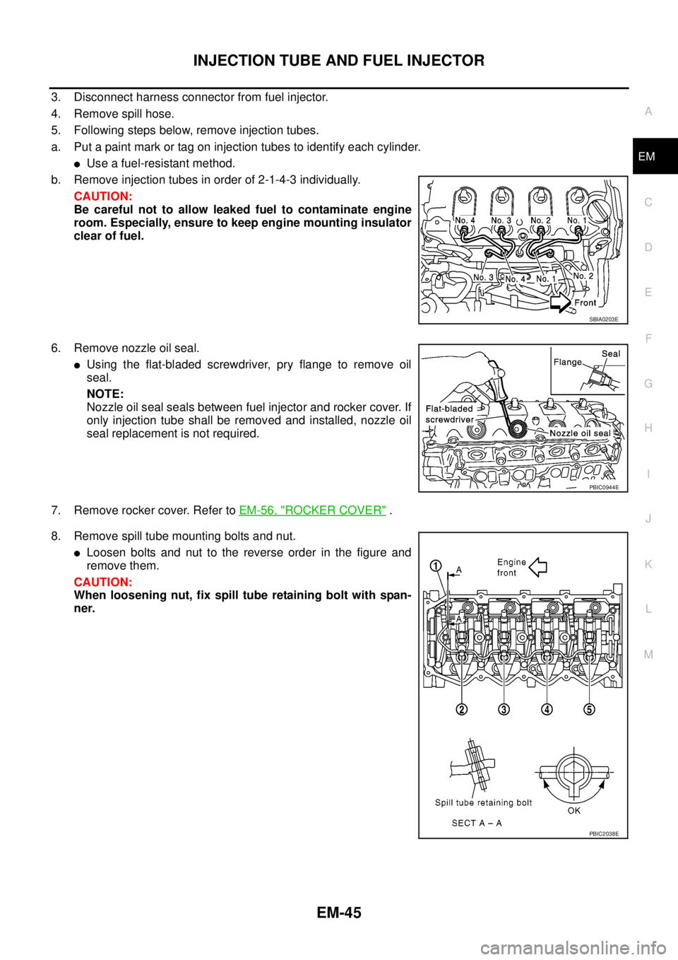
5. Following steps below, remove injection tubes.
a. Put a paint mark or tag on injection tubes to identify each cylinder.
lUse a fuel-resistant method.
b. Remove injection tubes in order of 2-1-4-3 individually.
CAUTION:
Be careful not to allow leaked fuel to contaminate engine
room. Especially, ensure to keep engine mounting insulator
clear of fuel.
6. Remove nozzle oil seal.
lUsing the flat-bladed screwdriver, pry flange to remove oil
seal.
NOTE:
Nozzle oil seal seals between fuel injector and rocker cover. If
only injection tube shall be removed and installed, nozzle oil
seal replacement is not required.
7. Remove rocker cover. Refer toEM-56, "
ROCKER COVER".
8. Remove spill tube mounting bolts and nut.
lLoosen bolts and nut to the reverse order in the figure and
remove them.
CAUTION:
When loosening nut, fix spill tube retaining bolt with span-
ner.
SBIA0203E
PBIC0944E
PBIC2038E
Page 1428 of 3171
EM-46
INJECTION TUBE AND FUEL INJECTOR
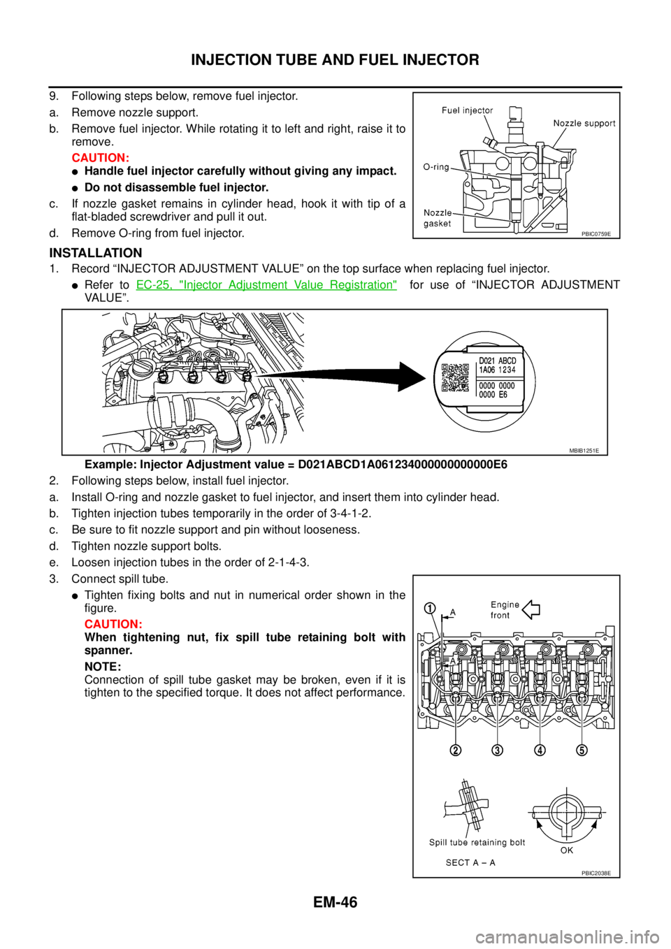
9. Following steps below, remove fuel injector.
a. Remove nozzle support.
b. Remove fuel injector. While rotating it to left and right, raise it to
remove.
CAUTION:
lHandle fuel injector carefully without giving any impact.
lDo not disassemble fuel injector.
c. If nozzle gasket remains in cylinder head, hook it with tip of a
flat-bladed screwdriver and pull it out.
d. Remove O-ring from fuel injector.
INSTALLATION
1. Record “INJECTOR ADJUSTMENT VALUE” on the top surface when replacing fuel injector.
lRefer toEC-25, "Injector Adjustment Value Registration"for use of “INJECTOR ADJUSTMENT
VALUE”.
Example: Injector Adjustment value = D021ABCD1A061234000000000000E6
2. Following steps below, install fuel injector.
a. Install O-ring and nozzle gasket to fuel injector, and insert them into cylinder head.
b. Tighten injection tubes temporarily in the order of 3-4-1-2.
c. Be sure to fit nozzle support and pin without looseness.
d. Tighten nozzle support bolts.
e. Loosen injection tubes in the order of 2-1-4-3.
3. Connect spill tube.
lTighten fixing bolts and nut in numerical order shown in the
figure.
CAUTION:
When tightening nut, fix spill tube retaining bolt with
spanner.
NOTE:
Connection of spill tube gasket may be broken, even if it is
tighten to the specified torque. It does not affect performance.
PBIC0759E
MBIB1251E
PBIC2038E
Page 1429 of 3171
INJECTION TUBE AND FUEL INJECTOR
EM-47
C
D
E
F
G
H
I
J
K
L
MA
EM
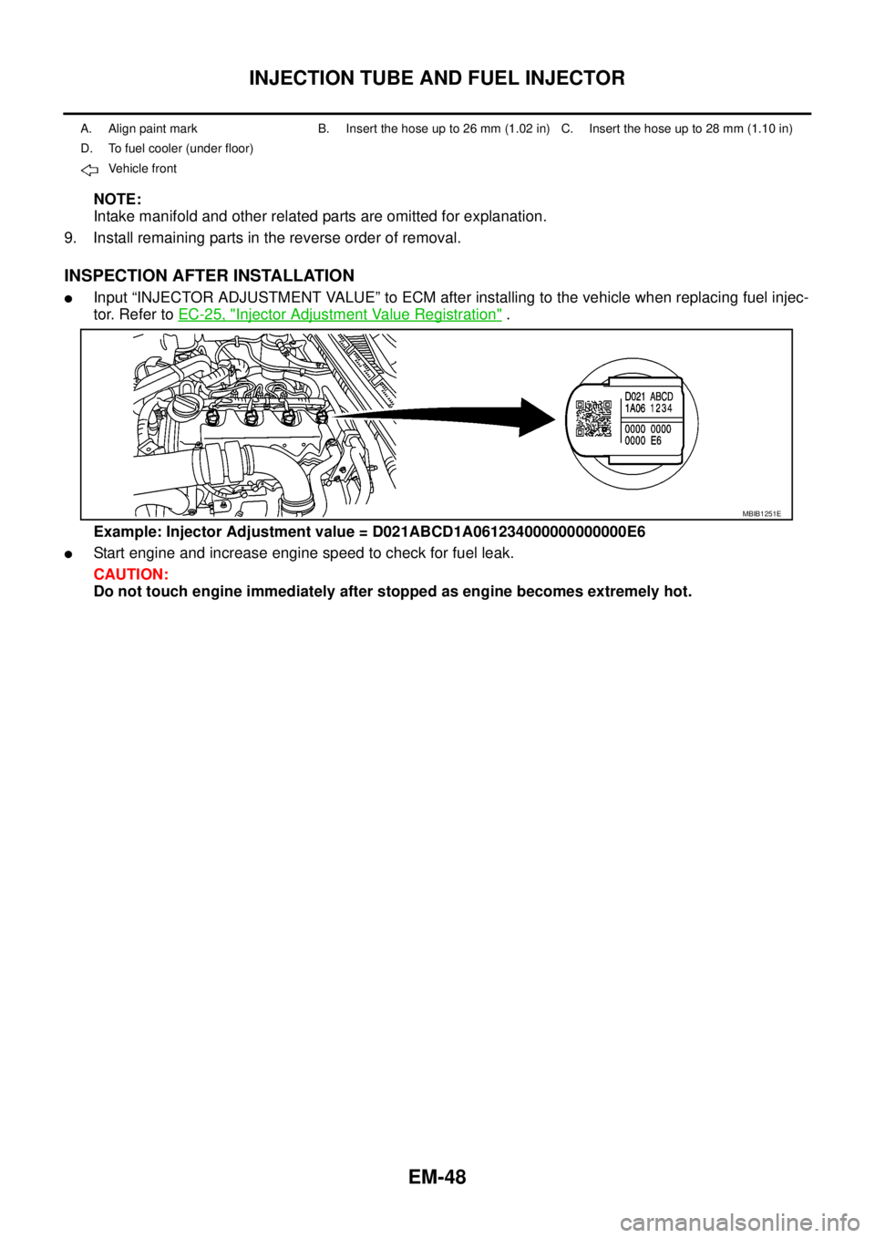
4. Perform air tightness test for spill tube.
lConnect a handy vacuum pump to spill connector. Make sure
that vacuum is retained while applying following vacuum.
lIf outside of standard, reconnect spill tube. (Replace gasket in
this case.)
5. Install rocker cover. Refer toEM-56, "
Removal and Installation".
6. Install nozzle oil seal.
lInsert it straight until its flange fully contacts rocker cover.
CAUTION:
lCheck gutter spring in nozzle oil seal on fuel injector for missing.
7. Connect injection tubes individually to each cylinder in order of
3-4-1-2.
8. Install fuel hoses, spill hose and fuel gallery as shown in the figure.Standard:
–53.3to–66.7kPa(–533to–667mbar,–400to
– 500 mmHg, – 15.75 to – 19.69 inHg)
JEF250Z
SBIA0203E
1. Rocker cover 2. Fuel filter (standard models) 3. Fuel pump
4. Fuel rail 5. Fuel filter (models for cold area)
PBIC3437E
Page 1430 of 3171
EM-48
INJECTION TUBE AND FUEL INJECTOR
NOTE:
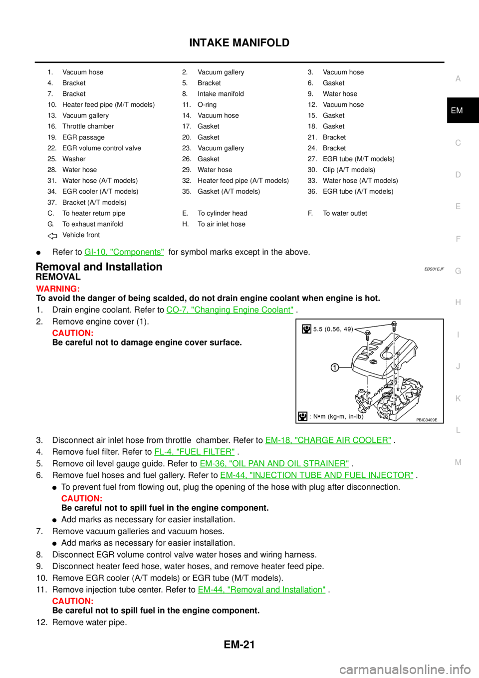
Intake manifold and other related parts are omitted for explanation.
9. Install remaining parts in the reverse order of removal.
INSPECTION AFTER INSTALLATION
lInput “INJECTOR ADJUSTMENT VALUE” to ECM after installing to the vehicle when replacing fuel injec-
tor. Refer toEC-25, "
Injector Adjustment Value Registration".
Example: Injector Adjustment value = D021ABCD1A061234000000000000E6
lStart engine and increase engine speed to check for fuel leak.
CAUTION:
Do not touch engine immediately after stopped as engine becomes extremely hot.
A. Align paint mark B. Insert the hose up to 26 mm (1.02 in) C. Insert the hose up to 28 mm (1.10 in)
D. To fuel cooler (under floor)
Ve h ic le f ro n t
MBIB1251E
Page 1432 of 3171
EM-50
FUEL PUMP
2. Remove fuel hose and spill hose from fuel pump. Refer toEM-44, "INJECTION TUBE AND FUEL INJEC-
TOR".
CAUTION:
Be careful not to spill fuel in the engine component.
3. Disconnect harness connectors from fuel pump.
4. Remove injection tube center, clip and insert rubber. Refer toEM-44, "
INJECTION TUBE AND FUEL
INJECTOR".
CAUTION:
Be careful not to spill fuel in the engine component.
5. Remove secondary timing chain. Refer toEM-73, "
SECONDARY TIMING CHAIN".
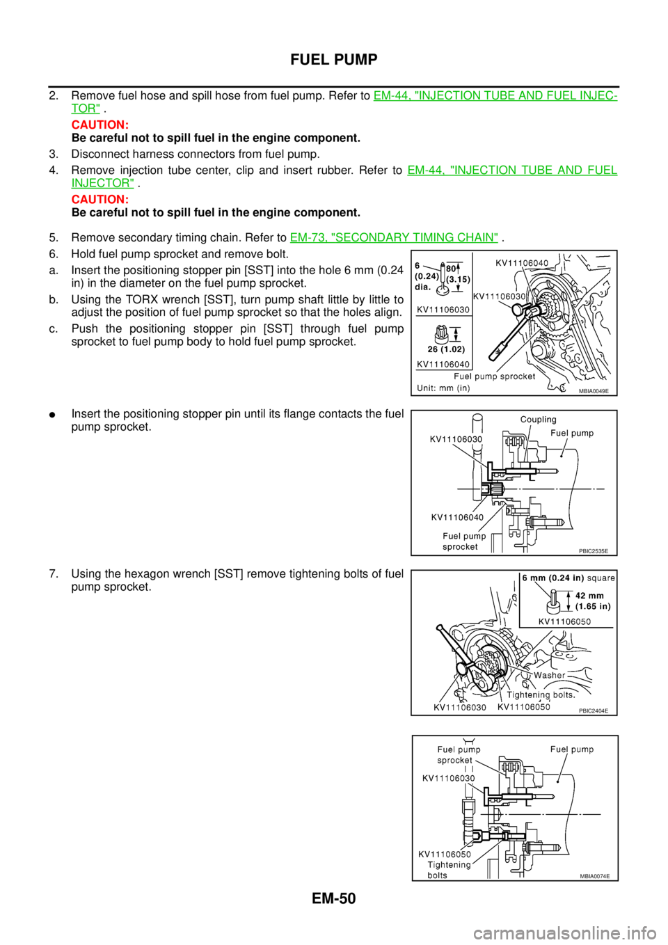
6. Hold fuel pump sprocket and remove bolt.
a. Insert the positioning stopper pin [SST] into the hole 6 mm (0.24
in) in the diameter on the fuel pump sprocket.
b. Using the TORX wrench [SST], turn pump shaft little by little to
adjust the position of fuel pump sprocket so that the holes align.
c. Push the positioning stopper pin [SST] through fuel pump
sprocket to fuel pump body to hold fuel pump sprocket.
lInsert the positioning stopper pin until its flange contacts the fuel
pump sprocket.
7. Using the hexagon wrench [SST] remove tightening bolts of fuel
pump sprocket.
MBIA0049E
PBIC2535E
PBIC2404E
MBIA0074E
Page 1437 of 3171
FUEL PUMP
EM-55
C
D
E
F
G
H
I
J
K
L
MA
EM
13. Install secondary timing chain. Refer toEM-73, "SECONDARY TIMING CHAIN".
14. Following steps below, install injection tube center. Refer toEM-44, "
INJECTION TUBE AND FUEL
INJECTOR".
a. Pre-set clip and insert rubber to injection tube center.
b. Pre-tight nut of injection tube center to fuel pump and fuel rail by hand. (until seal surface touched)
c. Adjust clip dimension and tight bolt for clip to intake manifold by tool.
d. Tight nut of injection tube center to fuel pump by tool.
e. Tight nut of injection tube center to fuel rail by tool.
15. Connect the harness connector to fuel pump.
16. Install fuel hoses. Refer toEM-44, "
INJECTION TUBE AND FUEL INJECTOR".
17. Hereafter, install in the reverse order of removal.
CAUTION:
When fuel pump is replaced with new one or another one, perform fuel pump leaning value clean-
ing before starting engine. Refer toEC-24, "
Fuel Pump Learning Value Clearing".