2005 NISSAN NAVARA wiper fluid
[x] Cancel search: wiper fluidPage 1756 of 3171
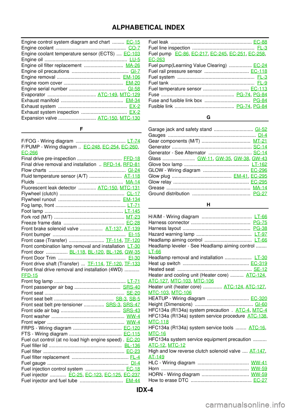
IDX-4
ALPHABETICAL INDEX
Engine control system diagram and chart .........EC-15
Engine coolant ....................................................CO-7
Engine coolant temperature sensor (ECTS) ....EC-103
Engine oil .............................................................LU-5
Engine oil filter replacement .............................MA-26
Engine oil precautions ..........................................GI-7
Engine removal ...............................................EM-106
Engine room cover ............................................EM-20
Engine serial number ..........................................GI-58
Evaporator ....................................ATC-149,MTC-129
Exhaust manifold ..............................................EM-34
Exhaust system ...................................................EX-2
Exhaust system inspection ..................................EX-2
Expansion valve ............................ATC-150,MTC-130
F
F/FOG - Wiring diagram .....................................LT-74
F/PUMP - Wiring diagram ..EC-248,EC-254,EC-260,
EC-266
Final drive pre-inspection .................................FFD-18
Final drive removal and installation ..RFD-14,RFD-81
Flow charts .........................................................GI-24
Fluid temperature sensor (A/T) ........................AT-118
Fluids ................................................................MA-14
Fluorescent leak detector .............ATC-150,MTC-131
Flywheel (clutch) ................................................CL-17
Flywheel runout ..............................................EM-134
Fog lamp, front ....................................................LT-71
Foot lamp ..........................................................LT-145
Fork rod (M/T) ....................................................MT-23
Freeze frame data .............................................EC-28
Front brake solenoid valve .................AT-137,AT-139
Front bumper ......................................................EI-15
Front case (Transfer) ..........................TF-114,TF-120
Front combination lamp removal and installationLT-30
Front door ................BL-118,BL-120,BL-126,GW-35
Front Door Trim ..................................................EI-30
Front drive shaft (Transfer) ...TF-114,TF-120,TF-133
Front final drive removal and installation (4WD) ...........
FFD-15
Front fog lamp .....................................................LT-71
Front passenger air bag ..................................SRS-40
Front seat ...........................................................SE-20
Front seat belt ............................................SB-3,SB-5
Front seat belt pre-tensioner ...............SRS-3,SRS-47
Front side air bag ............................................SRS-43
Front washer ......................................................WW-4
Front wiper .........................................................WW-4
FRPS - Wiring diagram ....................................EC-120
FTS - Wiring diagram .......................................EC-115
Fuel cut control (at no load high engine speed) .EC-20
Fuel filler lid ......................................................BL-136
Fuel filter ............................................................EC-23
Fuel filter replacement ..........................................FL-4
Fuel gauge ............................................................DI-4
Fuel injection control system .............................EC-18
Fuel injector ............EC-25,EC-123,EC-125,EC-237
Fuel injector and fuel tube ................................EM-44
Fuel leak ............................................................EC-88
Fuel line inspection ..............................................FL-3
Fuel pumpEC-86,EC-217,EC-245,EC-251,EC-258,
EC-263
Fuel pump(Learning Value Clearing) .................EC-24
Fuel rail pressure sensor .................................EC-118
Fuel system .........................................................FL-3
Fuel tank ..............................................................FL-9
Fuel temperature sensor ..................................EC-113
Fuse ......................................................PG-74,PG-84
Fuse and fusible link box ..................................PG-84
Fusible link ............................................PG-74,PG-84
G
Garage jack and safety stand .............................GI-52
Gauges .................................................................DI-4
Gear components (M/T) ....................................MT-21
Generator ...........................................................SC-14
Generator - See Alternator ................................SC-14
Glass ........................GW-11,GW-35,GW-38,GW-43
Glove box lamp ................................................LT-162
GLOW - Wiring diagram ..................................EC-296
Glow plug ............................................EM-41,EC-295
Glow relay ........................................................EC-295
Grease ..............................................................MA-14
Ground distribution ...........................................PG-27
H
H/AIM - Wiring diagram .....................................LT-66
Harness connector ............................................PG-75
Harness layout ..................................................PG-38
Hazard warning lamp .........................................LT-97
Headlamp aiming control ...................................LT-66
Headlamp leveler - See Headlamp aiming control ........
LT-66
Headlamp removal and installation ....................LT-30
Heat up switch .................................................EC-319
Heated seat .......................................................SE-12
Heater and cooling unit (Heater core) ..........ATC-124,
ATC-127
,MTC-103,MTC-106
Heater unit (heater core) ..............ATC-124,ATC-127,
MTC-103
,MTC-106
HEATUP - Wiring diagram ...............................EC-320
Height (Dimensions) ...........................................GI-60
HFC134a (R134a) system precaution .ATC-4,MTC-4
HFC134a (R134a) system service procedureATC-138,
MTC-118
HFC134a (R134a) system service tools ........ATC-16,
MTC-16
HFC134a system service equipment precaution ..........
ATC-12
,MTC-12
High and low reverse clutch solenoid valve ....AT-147,
AT-149
HLC - Wiring diagram ......................................WW-41
Horn .................................................................WW-59
HORN - Wiring diagram ...................................WW-59
How to erase DTC .............................................EC-27
Page 1812 of 3171
![NISSAN NAVARA 2005 Repair Workshop Manual CAN COMMUNICATION
LAN-35
[CAN]
C
D
E
F
G
H
I
J
L
MA
B
LAN
Closed throttle position signal T R
Cooling fan speed request signal TR
Engine coolant temperature signal T R R
Engine speed signal T R R R
En NISSAN NAVARA 2005 Repair Workshop Manual CAN COMMUNICATION
LAN-35
[CAN]
C
D
E
F
G
H
I
J
L
MA
B
LAN
Closed throttle position signal T R
Cooling fan speed request signal TR
Engine coolant temperature signal T R R
Engine speed signal T R R R
En](/manual-img/5/57362/w960_57362-1811.png)
CAN COMMUNICATION
LAN-35
[CAN]
C
D
E
F
G
H
I
J
L
MA
B
LAN
Closed throttle position signal T R
Cooling fan speed request signal TR
Engine coolant temperature signal T R R
Engine speed signal T R R R
Engine status signal T R R
Fuel consumption monitor signalTR
RT
Glow indicator signal T R
Glow relay signal T R
Malfunction indicator signal T R
Wide open throttle position signal T R
A/T fluid temperature sensor signal T R
A/T position indicator lamp signal T R
OD OFF indicator lamp signal T R
Output shaft revolution signal R T
Turbine revolution signal R T
A/C switch/indicator signal T R
PTC heater signal R T
A/C switch signal R R T
Buzzer output signal T R
Day time running light request signal R T R R
Door switch signalTR R
Front fog light request signal R T R R
Front wiper request signal T R
High beam request signal T R R
Horn chirp signalTR
Low beam request signal T R
Position light request signal T R R
Rear fog light request signal R T R
Rear window defogger switch signal R T R
Sleep wake up signal T R R
Theft warning horn request signal T R
Trailer lamp signalTR
Turn indicator signal T R
1st position switch signal R T
Distance to empty signal R T
Fuel level low warning signal R T
Overdrive control switch signal R T
Stop lamp switch signal R T
ABS operation signal R T
ABS warning lamp signalRT Signals ECM TCMNAVI
control
unitFront air
controlBCMCombi-
nation
meterABS
actuator
and elec-
tric unit
(control
unit)IPDM
E/R
Page 1819 of 3171
![NISSAN NAVARA 2005 Repair Workshop Manual LAN-42
[CAN]
CAN COMMUNICATION
Engine coolant temperature signal T R R
Engine speed signal T R R R R
Engine status signal T R R
Fuel consumption monitor signalTR
RT
Glow indicator signal T R
Glow rela NISSAN NAVARA 2005 Repair Workshop Manual LAN-42
[CAN]
CAN COMMUNICATION
Engine coolant temperature signal T R R
Engine speed signal T R R R R
Engine status signal T R R
Fuel consumption monitor signalTR
RT
Glow indicator signal T R
Glow rela](/manual-img/5/57362/w960_57362-1818.png)
LAN-42
[CAN]
CAN COMMUNICATION
Engine coolant temperature signal T R R
Engine speed signal T R R R R
Engine status signal T R R
Fuel consumption monitor signalTR
RT
Glow indicator signal T R
Glow relay signal T R
Malfunction indicator signal T R
Wide open throttle position signal T R
A/T fluid temperature sensor signal T R
A/T position indicator lamp signal T R R
OD OFF indicator lamp signal T R
Output shaft revolution signal R T R
Turbine revolution signal R T
A/C switch/indicator signal T R
Differential lock indicator signal T R
Differential lock switch signal T R
PTC heater signal
*RT
A/C switch signal R R T
Buzzer output signal T R
Day time running light request signal R T R R
Door switch signal T R R
Front fog light request signal R T R R
Front wiper request signal T R
High beam request signal T R R
Horn chirp signalTR
Low beam request signal T R
Position light request signal T R R
Rear fog light request signal R T R
Rear window defogger switch signal R T R
Sleepwakeupsignal T R R
Theft warning horn request signal T R
Trailer lamp signal T R
Turn indicator signal T R
1st position switch signal R T
Distance to empty signal R T
Fuel level low warning signal R T
Overdrive control switch signal R T
Stop lamp switch signal R TSignals ECM TCMNAVI
con-
trol
unitDiffer-
ential
lock
con-
trol
unitFront
air
controlBCMCom-
bina-
tion
meterTrans-
fer
con-
trol
unitABS
actua-
tor and
elec-
tric unit
(con-
trol
unit)IPDM
E/R
Page 2280 of 3171
DESCRIPTION
MA-5
C
D
E
F
G
H
I
J
K
MA
B
MA
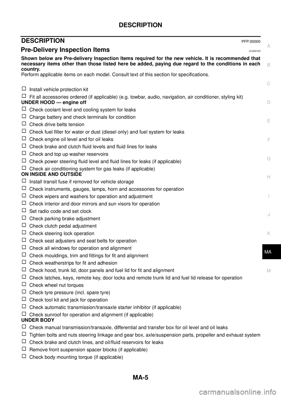
DESCRIPTIONPFP:00000
Pre-Delivery Inspection ItemsELS001K2
Shown below are Pre-delivery Inspection Items required for the new vehicle. It is recommended that
necessary items other than those listed here be added, paying due regard to the conditions in each
country.
Perform applicable items on each model. Consult text of this section for specifications.
Install vehicle protection kit
Fit all accessories ordered (if applicable) (e.g. towbar, audio, navigation, air conditioner, styling kit)
UNDER HOOD — engine off
Check coolant level and cooling system for leaks
Charge battery and check terminals for condition
Check drive belts tension
Check fuel filter for water or dust (diesel only) and fuel system for leaks
Check engine oil level and for oil leaks
Check brake and clutch fluid levels and fluid lines for leaks
Check and top up washer reservoirs
Check power steering fluid level and fluid lines for leaks (if applicable)
Check air conditioning system for gas leaks (if applicable)
ON INSIDE AND OUTSIDE
Install transit fuse if removed for vehicle storage
Check instruments, gauges, lamps, horn and accessories for operation
Check wipers and washers for operation and adjustment
Check interior and door mirrors and sun visors for operation
Set radio code and set clock
Check parking brake adjustment
Check clutch pedal adjustment
Check steering lock operation
Check seat adjusters and seat belts for operation
Check all windows for operation and alignment
Check mouldings, trim and fittings for fit and alignment
Check weatherstrips for fit and adhesion
Check hood, trunk lid, door panels and fuel lid for fit and alignment
Check latches, keys, remote key, door locks and remote trunk lid and fuel lid release for operation
Check wheel nut torques
Check tyre pressure (incl. spare tyre)
Check tool kit and jack for operation
Check automatic transmission/transaxle starter inhibitor (if applicable)
Check sunroof for operation and alignment (if applicable)
UNDER BODY
Check manual transmission/transaxle, differential and transfer box for oil level and oil leaks
Tighten bolts and nuts steering linkage and gear box, axle/suspension parts, propeller and exhaust system
Check brake and clutch lines, and oil/fluid reservoirs for leaks
Remove front suspension spacer blocks (if applicable)
Check body mounting torque (if applicable)
Page 2282 of 3171
GENERAL MAINTENANCE
MA-7
C
D
E
F
G
H
I
J
K
MA
B
MA
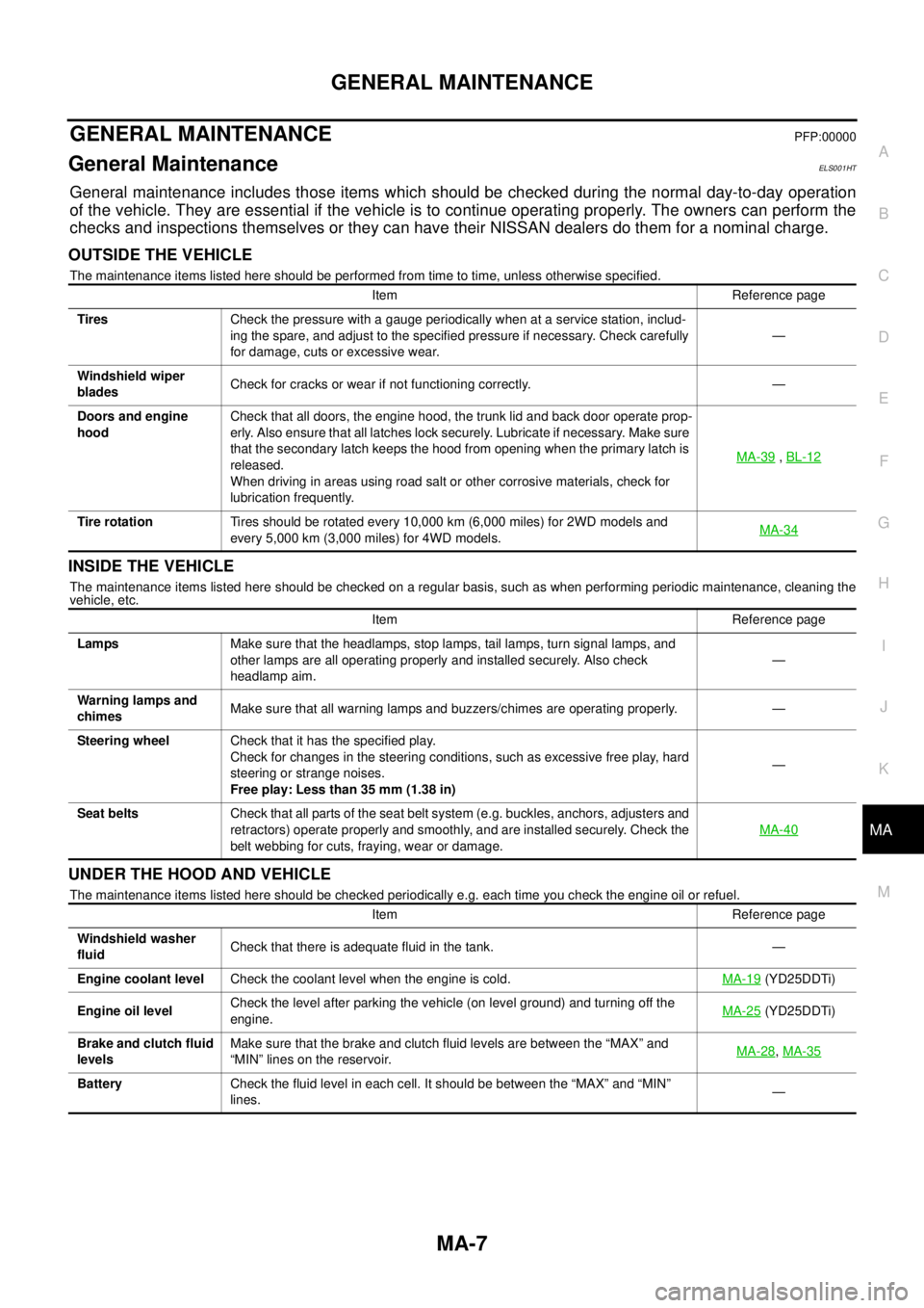
GENERAL MAINTENANCEPFP:00000
General MaintenanceELS001HT
General maintenance includes those items which should be checked during the normal day-to-day operation
of the vehicle. They are essential if the vehicle is to continue operating properly. The owners can perform the
checks and inspections themselves or they can have their NISSAN dealers do them for a nominal charge.
OUTSIDE THE VEHICLE
The maintenance items listed here should be performed from time to time, unless otherwise specified.
INSIDE THE VEHICLE
The maintenance items listed here should be checked on a regular basis, such as when performing periodic maintenance, cleaning the
vehicle, etc.
UNDER THE HOOD AND VEHICLE
The maintenance items listed here should be checked periodically e.g. each time you check the engine oil or refuel.Item Reference page
TiresCheck the pressure with a gauge periodically when at a service station, includ-
ing the spare, and adjust to the specified pressure if necessary. Check carefully
for damage, cuts or excessive wear.—
Windshield wiper
bladesCheck for cracks or wear if not functioning correctly. —
Doors and engine
hoodCheck that all doors, the engine hood, the trunk lid and back door operate prop-
erly. Also ensure that all latches lock securely. Lubricate if necessary. Make sure
that the secondary latch keeps the hood from opening when the primary latch is
released.
When driving in areas using road salt or other corrosive materials, check for
lubrication frequently.MA-39
,BL-12
Tire rotationTires should be rotated every 10,000 km (6,000 miles) for 2WD models and
every 5,000 km (3,000 miles) for 4WD models.MA-34
Item Reference page
LampsMake sure that the headlamps, stop lamps, tail lamps, turn signal lamps, and
other lamps are all operating properly and installed securely. Also check
headlamp aim.—
Warning lamps and
chimesMake sure that all warning lamps and buzzers/chimes are operating properly. —
Steering wheelCheck that it has the specified play.
Check for changes in the steering conditions, such as excessive free play, hard
steering or strange noises.
Free play: Less than 35 mm (1.38 in)—
Seat beltsCheck that all parts of the seat belt system (e.g. buckles, anchors, adjusters and
retractors) operate properly and smoothly, and are installed securely. Check the
belt webbing for cuts, fraying, wear or damage.MA-40
Item Reference page
Windshield washer
fluidCheck that there is adequate fluid in the tank. —
Engine coolant levelCheck the coolant level when the engine is cold.MA-19
(YD25DDTi)
Engine oil levelCheck the level after parking the vehicle (on level ground) and turning off the
engine.MA-25
(YD25DDTi)
Brake and clutch fluid
levelsMake sure that the brake and clutch fluid levels are between the “MAX” and
“MIN” lines on the reservoir.MA-28
,MA-35
BatteryCheck the fluid level in each cell. It should be between the “MAX” and “MIN”
lines.—
Page 3112 of 3171
WW-1
WIPER, WASHER & HORN
K ELECTRICAL
CONTENTS
C
D
E
F
G
H
I
J
L
M
SECTIONWW
A
B
WW
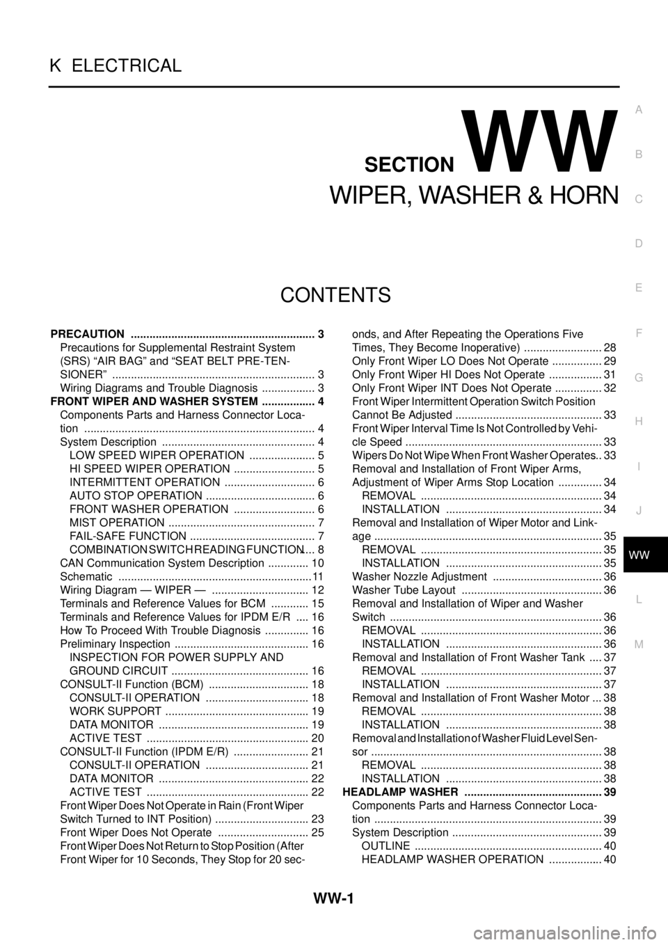
WIPER, WASHER & HORN
PRECAUTION ............................................................ 3
Precautions for Supplemental Restraint System
(SRS)“AIRBAG”and“SEATBELTPRE-TEN-
SIONER” .................................................................. 3
Wiring Diagrams and Trouble Diagnosis .................. 3
FRONT WIPER AND WASHER SYSTEM .................. 4
Components Parts and Harness Connector Loca-
tion ........................................................................... 4
System Description .................................................. 4
LOW SPEED WIPER OPERATION ...................... 5
HI SPEED WIPER OPERATION ........................... 5
INTERMITTENT OPERATION .............................. 6
AUTO STOP OPERATION .................................... 6
FRONT WASHER OPERATION ........................... 6
MIST OPERATION ................................................ 7
FAIL-SAFE FUNCTION ......................................... 7
COMBINATION SWITCH READING FUNCTION..... 8
CAN Communication System Description .............. 10
Schematic ............................................................... 11
Wiring Diagram — WIPER — ................................ 12
Terminals and Reference Values for BCM ............. 15
Terminals and Reference Values for IPDM E/R ..... 16
How To Proceed With Trouble Diagnosis ............... 16
Preliminary Inspection ............................................ 16
INSPECTION FOR POWER SUPPLY AND
GROUND CIRCUIT ............................................. 16
CONSULT-II Function (BCM) ................................. 18
CONSULT-II OPERATION .................................. 18
WORK SUPPORT ............................................... 19
DATA MONITOR ................................................. 19
ACTIVE TEST ..................................................... 20
CONSULT-II Function (IPDM E/R) ......................... 21
CONSULT-II OPERATION .................................. 21
DATA MONITOR ................................................. 22
ACTIVE TEST ..................................................... 22
Front Wiper Does Not Operate in Rain (Front Wiper
Switch Turned to INT Position) ............................... 23
Front Wiper Does Not Operate .............................. 25
Front Wiper Does Not Return to Stop Position (After
Front Wiper for 10 Seconds, They Stop for 20 sec-onds, and After Repeating the Operations Five
Times, They Become Inoperative) .......................... 28
Only Front Wiper LO Does Not Operate ................. 29
Only Front Wiper HI Does Not Operate .................. 31
Only Front Wiper INT Does Not Operate ................ 32
Front Wiper Intermittent Operation Switch Position
Cannot Be Adjusted ................................................ 33
Front Wiper Interval Time Is Not Controlled by Vehi-
cle Speed ................................................................ 33
Wipers Do Not Wipe When Front Washer Operates... 33
Removal and Installation of Front Wiper Arms,
Adjustment of Wiper Arms Stop Location ............... 34
REMOVAL ........................................................... 34
INSTALLATION ................................................... 34
Removal and Installation of Wiper Motor and Link-
age .......................................................................... 35
REMOVAL ........................................................... 35
INSTALLATION ................................................... 35
Washer Nozzle Adjustment .................................... 36
Washer Tube Layout .............................................. 36
Removal and Installation of Wiper and Washer
Switch ..................................................................... 36
REMOVAL ........................................................... 36
INSTALLATION ................................................... 36
Removal and Installation of Front Washer Tank ..... 37
REMOVAL ........................................................... 37
INSTALLATION ................................................... 37
Removal and Installation of Front Washer Motor ... 38
REMOVAL ........................................................... 38
INSTALLATION ................................................... 38
Removal and Installation of Washer Fluid Level Sen-
sor ........................................................................... 38
REMOVAL ........................................................... 38
INSTALLATION ................................................... 38
HEADLAMP WASHER ............................................. 39
Components Parts and Harness Connector Loca-
tion .......................................................................... 39
System Description ................................................. 39
OUTLINE ............................................................. 40
HEADLAMP WASHER OPERATION .................. 40
Page 3145 of 3171
WW-34
FRONT WIPER AND WASHER SYSTEM
Removal and Installation of Front Wiper Arms, Adjustment of Wiper Arms Stop
Location
EKS00P5E
REMOVAL
1. Operate wiper motor, and stop it at the auto stop position.
2. Remove wiper arm mounting nuts covers.
3. Remove wiper arm mounting nuts, then remove wiper arms.
INSTALLATION
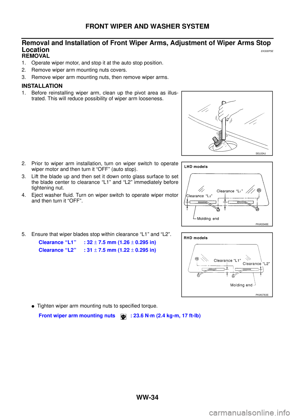
1. Before reinstalling wiper arm, clean up the pivot area as illus-
trated. This will reduce possibility of wiper arm looseness.
2. Prior to wiper arm installation, turn on wiper switch to operate
wiper motor and then turn it “OFF” (auto stop).
3. Lift the blade up and then set it down onto glass surface to set
the blade center to clearance “L1” and “L2” immediately before
tightening nut.
4. Eject washer fluid. Turn on wiper switch to operate wiper motor
and then turn it “OFF”.
5. Ensure that wiper blades stop within clearance “L1” and “L2”.
lTighten wiper arm mounting nuts to specified torque.
SEL024J
PKIA5548E
Clearance “L1” : 32±7.5 mm (1.26±0.295 in)
Clearance “L2” : 31±7.5 mm (1.22±0.295 in)
PKIA5763E
Front wiper arm mounting nuts : 23.6 N·m (2.4 kg-m, 17 ft-lb)
Page 3147 of 3171
WW-36
FRONT WIPER AND WASHER SYSTEM
Washer Nozzle Adjustment
EKS00P5G
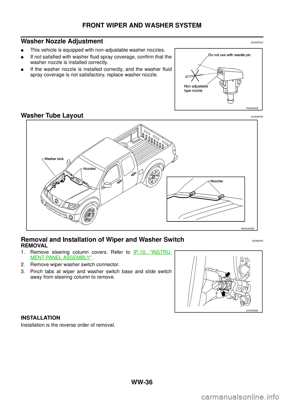
lThis vehicle is equipped with non-adjustable washer nozzles.
lIf not satisfied with washer fluid spray coverage, confirm that the
washer nozzle is installed correctly.
lIf the washer nozzle is installed correctly, and the washer fluid
spray coverage is not satisfactory, replace washer nozzle.
Washer Tube LayoutEKS00P5H
Removal and Installation of Wiper and Washer SwitchEKS00P5I
REMOVAL
1. Remove steering column covers. Refer toIP-10, "INSTRU-
MENT PANEL ASSEMBLY".
2. Remove wiper washer switch connector.
3. Pinch tabs at wiper and washer switch base and slide switch
away from steering column to remove.
INSTALLATION
Installation is the reverse order of removal.
PKIA2552E
WKIA3453E
LKIA0536E