2005 NISSAN NAVARA width
[x] Cancel search: widthPage 94 of 3171

AT-86
TROUBLE DIAGNOSIS
CAN DIAGNOSTIC SUPPORT MONITOR MODE
Operation Procedure
1. PerformAT- 7 9 , "CONSULT-II SETTING PROCEDURE".
2. Touch “CAN DIAG SUPPORT MNTR”. Refer toLAN-15, "
CAN
Diagnostic Support Monitor".
DTC WORK SUPPORT MODE
Operation Procedure
1. PerformAT- 7 9 , "CONSULT-II SETTING PROCEDURE".
2. Touch “DTC WORK SUPPORT”.
START RLY MON — —
NEXT GR POSI — —
SHIFT MODE — —
MANU GR POSI — —
VEHICLE SPEED (km/h) — X Vehicle speed recognized by TCM.
Vo l ta g e (V ) — —Displays the value measured by the voltage
probe.
Frequency (Hz) — —
The value measured by the pulse probe is dis-
played. DUTY-HI (high) (%) — —
DUTY-LOW (low) (%) — —
PLS WIDTH-HI (ms) — —
PLS WIDTH-LOW (ms) — —Monitored item (Unit)Monitor Item Selection
Remarks ECU
INPUT
SIGNALSMAIN SIG-
NALSSELEC-
TION
FROM
MENU
BCIA0031E
BCIA0031E
Page 821 of 3171

SERVICE DATA AND SPECIFICATIONS (SDS)
BR-35
C
D
E
G
H
I
J
K
L
MA
B
BR
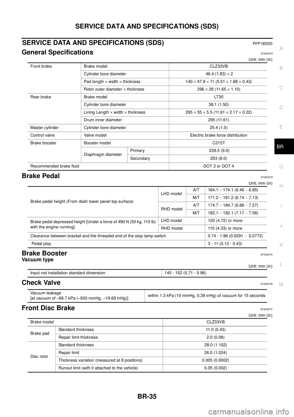
SERVICE DATA AND SPECIFICATIONS (SDS)PFP:00030
General SpecificationsEFS005T8
Unit: mm (in)
Brake PedalEFS005T9
Unit: mm (in)
Brake BoosterEFS005TA
Va c u u m t y p e
Unit: mm (in)
Check ValveEFS005TB
Front Disc BrakeEFS005TC
Unit: mm (in) Front brake Brake model CLZ33VB
Cylinder bore diameter 46.4 (1.83)´2
Pad length´width´thickness 140´47.8´11 ( 5 . 5 1´1.88´0.43)
Rotor outer diameter´thickness 296´28 (11.65´1.10)
Rear brake Brake model LT30
Cylinder bore diameter 38.1 (1.50)
Lining Length´width´thickness 295´55´5.5 (11.61´2.17´0.22)
Drum inner diameter 295 (11.61)
Master cylinder Cylinder bore diameter 25.4 (1.0)
Control valve Valve model Electric brake force distribution
Brake booster Booster model C215T
Diaphragm diameterPrimary 228.5 (9.0)
Secondary 203 (8.0)
Recommended brake fluid DOT 3 or DOT 4
Brake pedal height (From dash lower panel top surface)LHD modelA/T 164.1-174.1 (6.46-6.85)
M/T 171.2-181.2 (6.74-7.13)
RHD modelA/T 174.7-184.7 (6.88-7.27)
M/T 182.1-192.1 (7.17-7.56)
Brake pedal depressed height [Under a force of 490 N (50 kg, 110 lb)
with the engine running]LHD model 120 (4.72) or more
RHD model 110 (4.33) or more
Clearance between bracket and the threaded end of the stop lamp switch 0.74 - 1.96 (0.0291 - 0.0772)
Pedal play3-11(0.12-0.43)
Input rod installation standard dimension 145 - 152 (5.71 - 5.98)
Vacuum leakage
[at vacuum of –66.7 kPa (–500 mmHg, –19.69 inHg)]within 1.3 kPa (10 mmHg, 0.39 inHg) of vacuum for 15 seconds
Brake modelCLZ33VB
Brake padStandard thickness 11.0 (0.43)
Repair limit thickness 2.0 (0.08)
Disc rotorStandard thickness 28.0 (1.102)
Repair limit 26.0 (1.024)
Thickness variation (measured at 8 positions) 0.005 (0.0002)
Runout limit (with it attached to the vehicle) 0.05 (0.002)
Page 1043 of 3171
![NISSAN NAVARA 2005 Repair Workshop Manual TROUBLE DIAGNOSIS
EC-63
C
D
E
F
G
H
I
J
K
L
MA
ECACT CR PRESS [MPa]´´
lThe Fuel rail pressure (determined by
the signal voltage of the fuel rail pres-
sure sensor) is displayed.
BATTERY VOLT [V]´´ NISSAN NAVARA 2005 Repair Workshop Manual TROUBLE DIAGNOSIS
EC-63
C
D
E
F
G
H
I
J
K
L
MA
ECACT CR PRESS [MPa]´´
lThe Fuel rail pressure (determined by
the signal voltage of the fuel rail pres-
sure sensor) is displayed.
BATTERY VOLT [V]´´](/manual-img/5/57362/w960_57362-1042.png)
TROUBLE DIAGNOSIS
EC-63
C
D
E
F
G
H
I
J
K
L
MA
ECACT CR PRESS [MPa]´´
lThe Fuel rail pressure (determined by
the signal voltage of the fuel rail pres-
sure sensor) is displayed.
BATTERY VOLT [V]´´
lThe power supply voltage of ECM is
displayed.
P/N POSI SW [ON/OFF]´´
lIndicates [ON/OFF] condition from the
park/neutral position switch signal.
START SIGNAL [ON/OFF]´´
lIndicates [ON/OFF] condition from the
starter signal.
AIR COND SIG [ON/OFF]´´
lIndicates [ON/OFF] condition of the air
conditioner switch as determined by
the air conditioner signal.
BRAKE SW [ON/OFF]´´
lIndicates [ON/OFF] condition from the
stop lamp switch signal.
BRAKE SW2 [ON/OFF]´´
lIndicates [ON/OFF] condition from the
ASCD brake switch and ASCD clutch
switch signal.
IGN SW [ON/OFF]´´
lIndicates [ON/OFF] condition from
ignition switch signal.
WARM UP SW [ON/OFF]´
lIndicates [ON/OFF] condition from
heat up switch signal.
MAS AIR/FL SE [V]´´
lThe signal voltage of the mass air flow
sensor is displayed.This signal is converted by ECM inter-
nally. Thus, these differ from ECM termi-
nals voltage.
MAIN INJ WID [msec]´
lIndicates the actual fuel injection pulse
width compensated by ECM according
to the input signals.
PUMP CURRENT [mA]´
lIndicates the fuel pump power supply
current from the ECM.
GLOW RLY [ON/OFF]´
lThe glow relay control condition
(determined by ECM according to the
input signal) is displayed.
COOLING FAN
[LOW/HI/OFF]´
lIndicates the control condition of the
cooling fans (determined by ECM
according to the input signal).
LOW ... Operates at low speed
HI ... Operates at high speed
OFF ... Stopped
EGR VOL CON/V [step]´
lIndicates the EGR volume control
value computed by the ECM accord-
ing to the input signals.
lThe opening becomes larger as the
value increases.
INT/A VOLUME [mg/]
lThe intake air volume computed from
the mass air flow sensor signal is dis-
played.
BARO SEN [kPa]´´
lThe barometric pressure (determined
by the signal voltage from the absolute
pressure sensor built into the ECM) is
displayed. MONITOR ITEMECM
INPUT
SIG-
NALMAIN
SIG-
NALSCONDITION SPECIFICATION
Page 1044 of 3171
![NISSAN NAVARA 2005 Repair Workshop Manual EC-64
TROUBLE DIAGNOSIS
NOTE:
Any monitored item that does not match the vehicle being diagnosed is deleted from the display automatically.
ACTIVE TEST MODE
INT/M PRES SE [kPa]
lTurbocharger boost (de NISSAN NAVARA 2005 Repair Workshop Manual EC-64
TROUBLE DIAGNOSIS
NOTE:
Any monitored item that does not match the vehicle being diagnosed is deleted from the display automatically.
ACTIVE TEST MODE
INT/M PRES SE [kPa]
lTurbocharger boost (de](/manual-img/5/57362/w960_57362-1043.png)
EC-64
TROUBLE DIAGNOSIS
NOTE:
Any monitored item that does not match the vehicle being diagnosed is deleted from the display automatically.
ACTIVE TEST MODE
INT/M PRES SE [kPa]
lTurbocharger boost (determined by
the signal voltage from the turbo-
charger boost sensor) is displayed.
CYL COUNT [1/2/3/4]
lThe cylinder being injected is dis-
played.
1 ... Cylinder No.1 is injected.
2 ... Cylinder No.2 is injected.
3 ... Cylinder No.3 is injected.
4 ... Cylinder No.4 is injected.
SET SW
[ON/OFF]´
lIndicates [ON/OFF] condition from
SET/COAST switch signal.
RESUME/ACC SW
[ON/OFF]´
lIndicates [ON/OFF] condition from
RESUME/ACCEL switch signal.
CANCEL SW
[ON/OFF]´
lIndicates [ON/OFF] condition from
CANCEL switch signal.
MAIN SW
[ON/OFF]´
lIndicates [ON/OFF] condition from
MAIN switch signal.
ASCD APPLY [YES/NO]
lDisplaying ASCD application status
stored in ECM.
VDC APPLY [YES/NO]
lDisplaying ESP application status
stored in ECM.
AC PRESS SEN [V]
lThe signal voltage from the refrigerant
pressure sensor is displayed.
Voltage [V]
Voltage, frequency, duty cycle or pulse
width measured by the probe.Only “#” is displayed if item is unable to
be measured.
Figures with “#”s are temporary ones.
They are the same figures as an actual
piece of data which was just previously
measured. [Hz] or [%] Frequency
[msec],[Hz]or[%]
DUTY-HI
DUTY-LOW
PLS WIDTH-HI
PLS WIDTH-LOWMONITOR ITEMECM
INPUT
SIG-
NALMAIN
SIG-
NALSCONDITION SPECIFICATION
TEST ITEM CONDITION JUDGEMENT CHECK ITEM (REMEDY)
POWER BAL-
ANCE
lEngine: After warming up, idle the
engine.
lA/C switch: OFF
lShift lever: P or N (A/T), Neutral
(M/T)
lCut off each injector signal one at
a time using CONSULT-IIEngine runs rough or dies.
lHarness and connectors
lCompression
lFuel injector
COOLING FAN *
lIgnition switch: ON
lOperate the cooling fan at LOW,
HI speed and turn OFF using
CONSULT-II.Cooling fan moves at LOW, HI
speed and stops.lHarness and connector
lCooling fan motor
lCooling fan relay
ENG COOLANT
TEMP
lEngine: Return to the original
trouble condition
lChange the engine coolant tem-
perature using CONSULT-II.If trouble symptom disappears, see
CHECK ITEM.
lHarness and connectors
lEngine coolant temperature sen-
sor
lFuel injector
Page 1513 of 3171

CYLINDER BLOCK
EM-131
C
D
E
F
G
H
I
J
K
L
MA
EM
lIf corrected, measure the bearing oil clearance of the corrected journal and/or pin. Then select the main
bearing or connecting rod bearing. Refer toEM-132, "
MAIN BEARING OIL CLEARANCE"and/orEM-
131, "CONNECTING ROD BEARING OIL CLEARANCE".
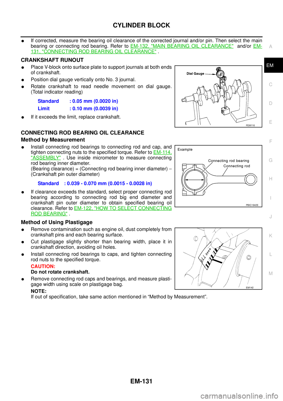
CRANKSHAFT RUNOUT
lPlace V-block onto surface plate to support journals at both ends
of crankshaft.
lPosition dial gauge vertically onto No. 3 journal.
lRotate crankshaft to read needle movement on dial gauge.
(Total indicator reading)
lIf it exceeds the limit, replace crankshaft.
CONNECTING ROD BEARING OIL CLEARANCE
Method by Measurement
lInstall connecting rod bearings to connecting rod and cap, and
tighten connecting nuts to the specified torque. Refer toEM-114,
"ASSEMBLY". Use inside micrometer to measure connecting
rod bearing inner diameter.
(Bearing clearance) = (Connecting rod bearing inner diameter)-
(Crankshaft pin outer diameter)
lIf clearance exceeds the standard, select proper connecting rod
bearing according to connecting rod big end diameter and
crankshaft pin outer diameter to obtain specified bearing oil
clearance. Refer toEM-122, "
HOW TO SELECT CONNECTING
ROD BEARING".
Method of Using Plastigage
lRemove contamination such as engine oil, dust completely from
crankshaft pins and each bearing surface.
lCut plastigage slightly shorter than bearing width, place it in
crankshaft direction, avoiding oil holes.
lInstall connecting rod bearings to caps, and tighten connecting
rod nuts to the specified torque.
CAUTION:
Do not rotate crankshaft.
lRemove connecting rod caps and bearings, and measure plasti-
gage width using scale on plastigage bag.
NOTE:
If out of specification, take same action mentioned in “Method by Measurement”.Standard : 0.05 mm (0.0020 in)
Limit : 0.10 mm (0.0039 in)
FEM116
Standard : 0.039 - 0.070 mm (0.0015 - 0.0028 in)
PBIC1642E
EM142
Page 1514 of 3171

EM-132
CYLINDER BLOCK
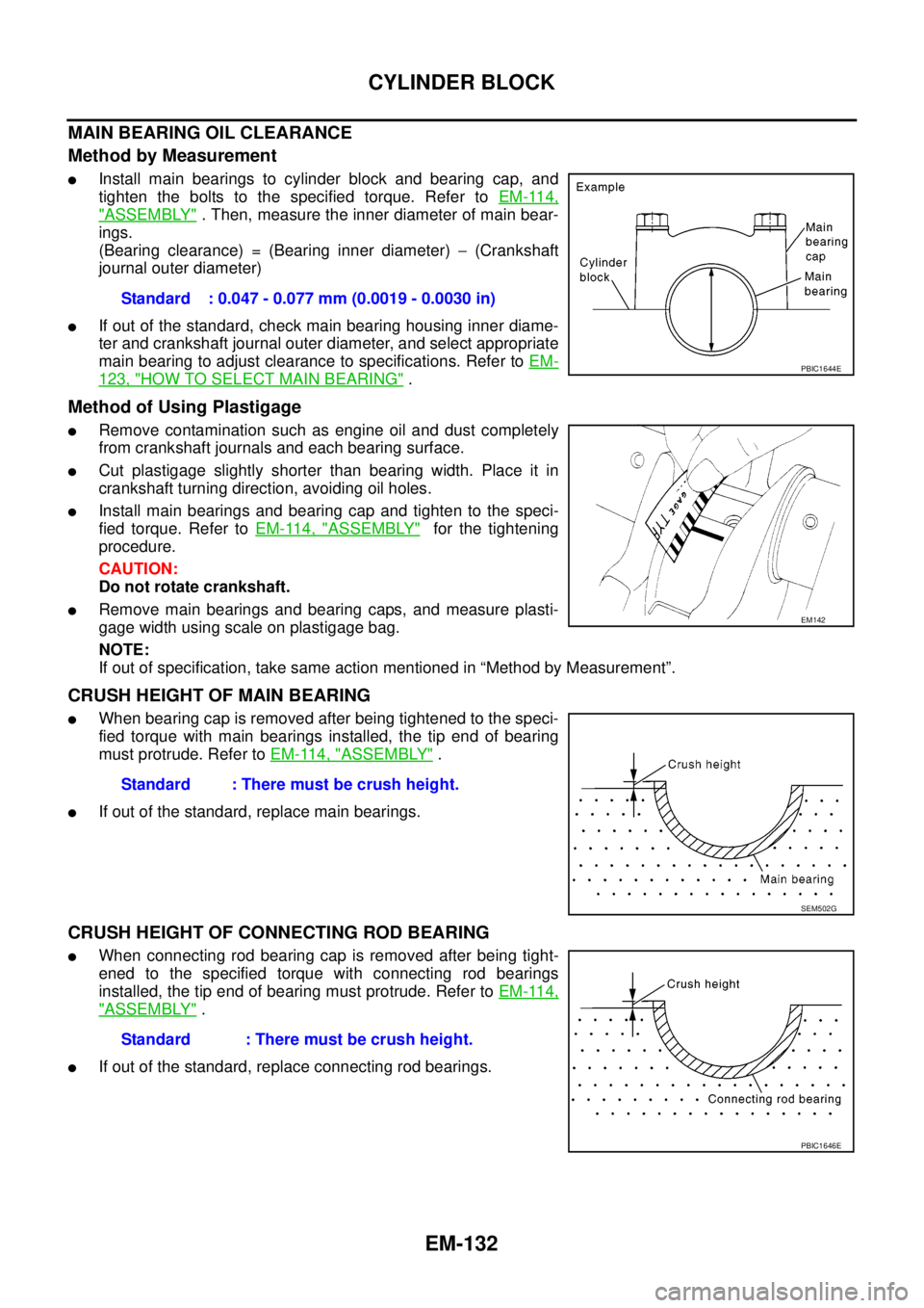
MAIN BEARING OIL CLEARANCE
Method by Measurement
lInstall main bearings to cylinder block and bearing cap, and
tighten the bolts to the specified torque. Refer toEM-114,
"ASSEMBLY". Then, measure the inner diameter of main bear-
ings.
(Bearing clearance) = (Bearing inner diameter)-(Crankshaft
journal outer diameter)
lIf out of the standard, check main bearing housing inner diame-
ter and crankshaft journal outer diameter, and select appropriate
main bearing to adjust clearance to specifications. Refer toEM-
123, "HOW TO SELECT MAIN BEARING".
Method of Using Plastigage
lRemove contamination such as engine oil and dust completely
from crankshaft journals and each bearing surface.
lCut plastigage slightly shorter than bearing width. Place it in
crankshaft turning direction, avoiding oil holes.
lInstall main bearings and bearing cap and tighten to the speci-
fied torque. Refer toEM-114, "
ASSEMBLY"for the tightening
procedure.
CAUTION:
Do not rotate crankshaft.
lRemove main bearings and bearing caps, and measure plasti-
gage width using scale on plastigage bag.
NOTE:
If out of specification, take same action mentioned in “Method by Measurement”.
CRUSH HEIGHT OF MAIN BEARING
lWhen bearing cap is removed after being tightened to the speci-
fied torque with main bearings installed, the tip end of bearing
must protrude. Refer toEM-114, "
ASSEMBLY".
lIf out of the standard, replace main bearings.
CRUSH HEIGHT OF CONNECTING ROD BEARING
lWhen connecting rod bearing cap is removed after being tight-
ened to the specified torque with connecting rod bearings
installed, the tip end of bearing must protrude. Refer toEM-114,
"ASSEMBLY".
lIf out of the standard, replace connecting rod bearings.Standard : 0.047 - 0.077 mm (0.0019 - 0.0030 in)
PBIC1644E
EM142
Standard : There must be crush height.
SEM502G
Standard : There must be crush height.
PBIC1646E
Page 1527 of 3171

SERVICE DATA AND SPECIFICATIONS (SDS)
EM-145
C
D
E
F
G
H
I
J
K
L
MA
EM
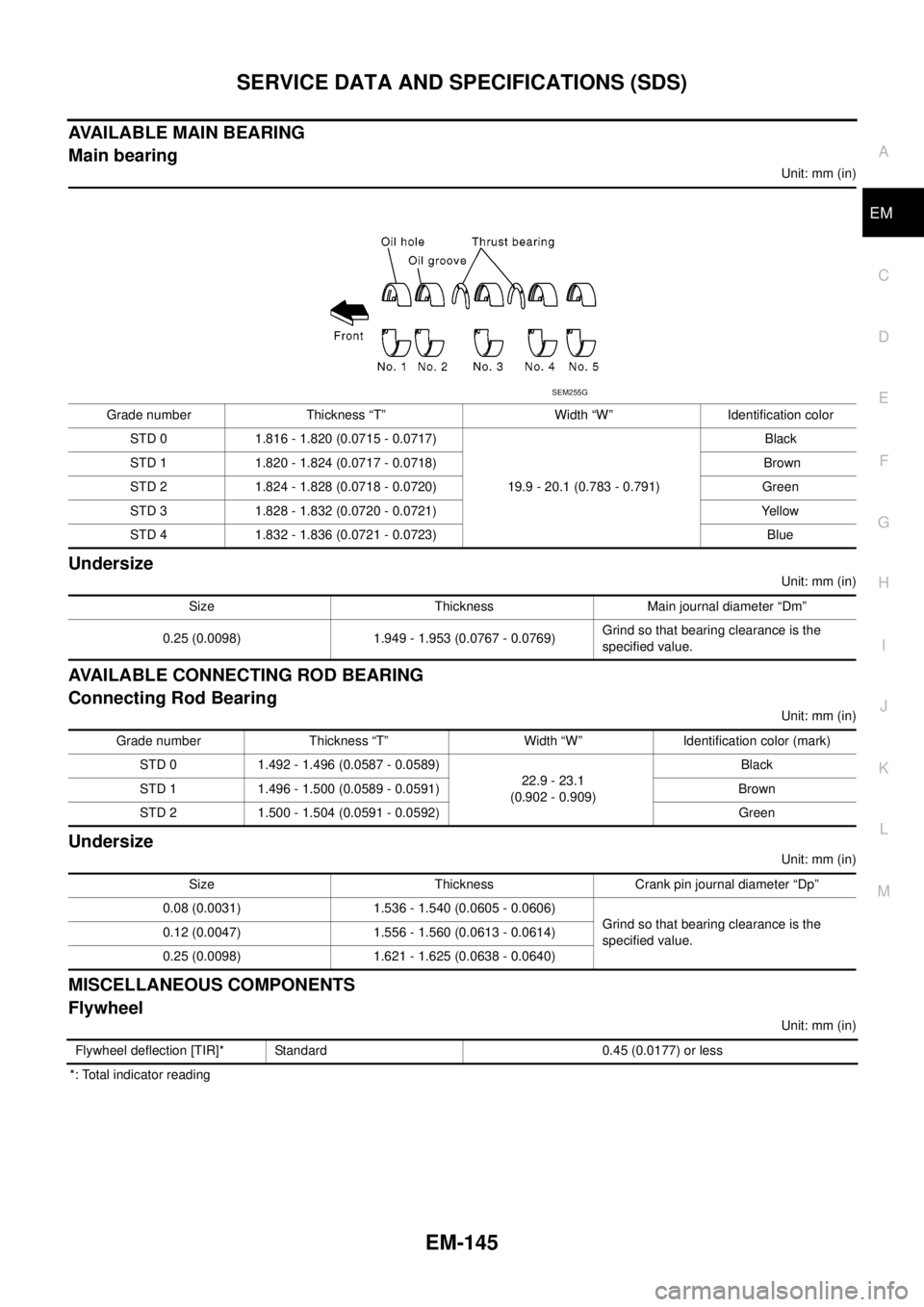
AVAILABLE MAIN BEARING
Main bearing
Unit: mm (in)
Undersize
Unit: mm (in)
AVAILABLE CONNECTING ROD BEARING
Connecting Rod Bearing
Unit: mm (in)
Undersize
Unit: mm (in)
MISCELLANEOUS COMPONENTS
Flywheel
Unit: mm (in)
*: Total indicator readingGrade number Thickness “T” Width “W” Identification color
STD 0 1.816 - 1.820 (0.0715 - 0.0717)
19.9 - 20.1 (0.783 - 0.791)Black
STD 1 1.820 - 1.824 (0.0717 - 0.0718) Brown
STD 2 1.824 - 1.828 (0.0718 - 0.0720) Green
STD 3 1.828 - 1.832 (0.0720 - 0.0721) Yellow
STD 4 1.832 - 1.836 (0.0721 - 0.0723) Blue
SEM255G
Size Thickness Main journal diameter “Dm”
0.25 (0.0098) 1.949 - 1.953 (0.0767 - 0.0769)Grind so that bearing clearance is the
specified value.
Grade number Thickness “T” Width “W” Identification color (mark)
STD 0 1.492 - 1.496 (0.0587 - 0.0589)
22.9 - 23.1
(0.902 - 0.909)Black
STD 1 1.496 - 1.500 (0.0589 - 0.0591) Brown
STD 2 1.500 - 1.504 (0.0591 - 0.0592) Green
Size Thickness Crank pin journal diameter “Dp”
0.08 (0.0031) 1.536 - 1.540 (0.0605 - 0.0606)
Grind so that bearing clearance is the
specified value. 0.12 (0.0047) 1.556 - 1.560 (0.0613 - 0.0614)
0.25 (0.0098) 1.621 - 1.625 (0.0638 - 0.0640)
Flywheel deflection [TIR]* Standard 0.45 (0.0177) or less
Page 1682 of 3171

GI-60
IDENTIFICATION INFORMATION
Dimensions
EAS001DO
KING CAB
Unit: mm (in)
DOUBLE CAB
Unit: mm (in)
Wheels & TyresEAS001DP
Drive Type 2WD 4WD
Tyre size 235/70R16 255/70R16 235/70R16 255/70R16 265/70R16 255/65R17
Overall length 5220 (205.5)
Overall width 1850 (72.8)
Overall height 1743 (68.6) 1756 (69.1) 1751 (68.9) 1766 (69.5) 1777 (70.0) 1771 (69.7)
Front tread width
1570 (61.8)
Rear tread width
Wheelbase 3200 (126.0)
Drive Type 2WD 4WD
Tyre size 255/70R16 255/65R17 235/70R16 255/70R16 265/70R16 255/65R17
Overall length 5220 (205.5)
Overall width 1850 (72.8)
Overall height
(with Roof Rack)1881 (74.1) 1885 (74.2) 1873 (73.7) 1888 (74.3) 1899 (74.8) 1893 (74.5)
Overall height
(without Roof Rack)1771 (69.7) 1775 (69.9) 1764 (69.4) 1779 (70.0) 1789 (70.4) 1784 (70.2)
Front tread width
1570 (61.8)
Rear tread width
Wheelbase 3200 (126.0)
Drive Type Road wheel Tyre Spare tyre size
All16 X 7J Steel 235/70R16 235/70R16
16 X 7J Aluminum Alloy235/70R16 235/70R16
255/70R16 255/70R16
17 X 7J Aluminum Alloy 255/65R17 255/65R17