Page 22 of 364
ENGINE – CYLINDER HEAD GASKET11-16
22. Alternator bracket connection
23. Inlet manifold stay
24. Eye bolt
25. Gasket
26. Eye bolt
27. Gasket
28. Oil feeder control valve pipe
29. Filter
30. Oil pipe joint
31. Gasket
32. Oil return pipe gasket
33. Oil return pipe
34. Oil return pipe gasket35. Oil return pipe gasket
36. Exhaust fitting bracket
•Water outlet fitting and thermostat case
assembly (Refer to Section 14: Water hose
pipe)
37. Water hose connection
38. Heater hose connection
39. Fuel return hose connection
40. Fuel high pressure hose connection
41. O-ring
42. Cylinder head bolt
43. Cylinder head assembly
44. Cylinder head gasket
(when
cool)
(engine oil)
(engine oil)
� �
E� �
�
�
D� �
�
�
C� �
� �
C� �
� �
A� �
�
�
B� �
� �
A� �
Page 35 of 364
ENGINE – ENGINE ASSY
11-29
Removal procedure
1. Ignition coil connector
2. O
2sensor connector
3. Oil feeder control valve connector
4. Crank angle sensor connector
5. Manifold absolute pressure sensor
connector
6. Fuel pressure solenoid valve connector
7. Knock sensor connector
8. Purge control solenoid valve connector
9. Throttle position connector
10. Injector connector11.Exhaust cam position sensor connector
12. Inlet cam position sensor connector
13. Water temperature gauge unit connector
14. Joint control harness and transmission
harness
15. Water temperature sensor connector
16. Alternator connector and terminal
17. Secondary air control solenoid valve
connector
18. Engine oil pressure switch connector
19. Drive belt
� �
A� �
Page 42 of 364

MPI – GENERAL13A-2
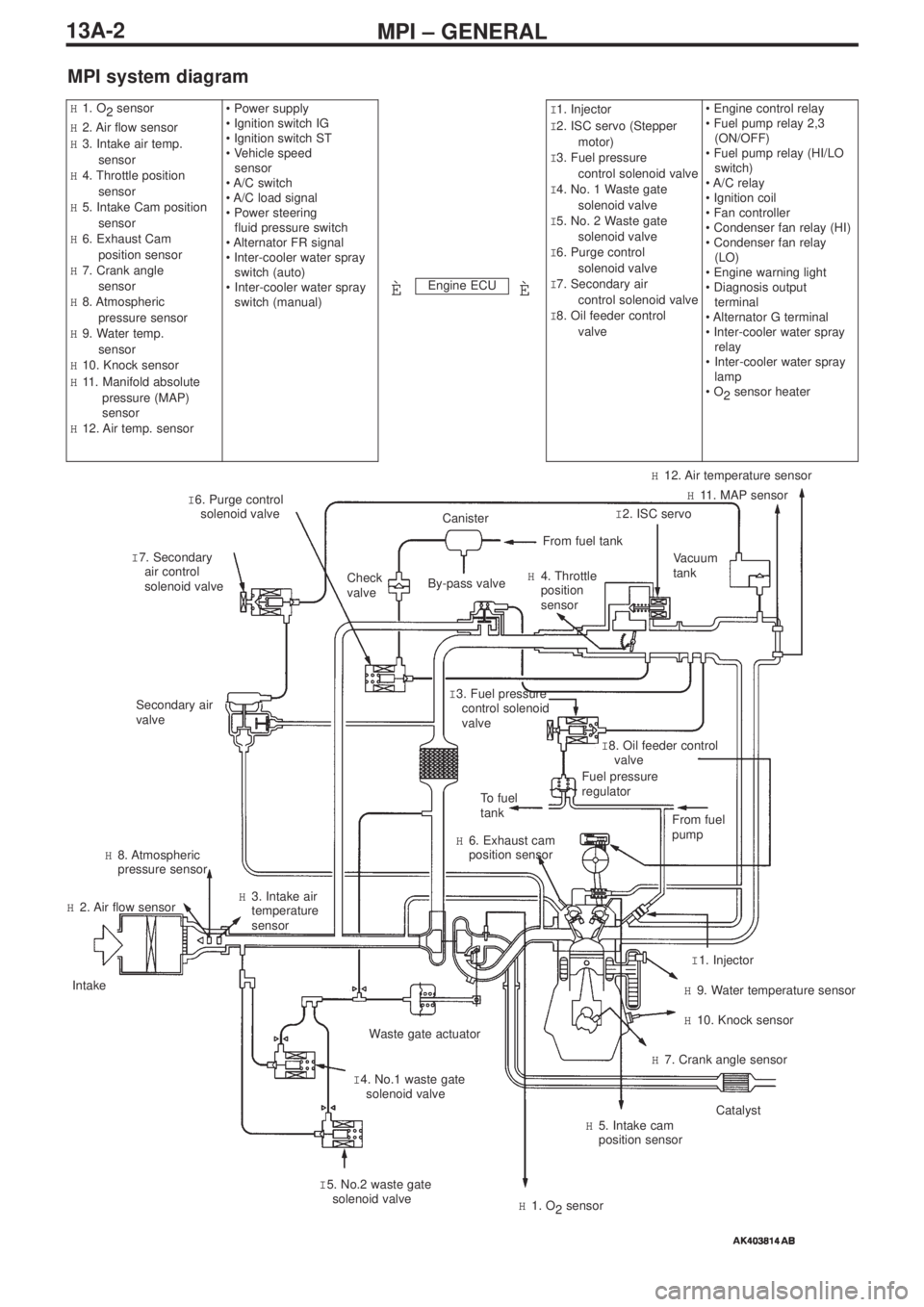
MPI system diagram
Engine ECU
H1. O
2 sensor
H2. Air flow sensor
H3. Intake air temp.
sensor
H4. Throttle position
sensor
H5. Intake Cam position
sensor
H6. Exhaust Cam
position sensor
H7. Crank angle
sensor
H8. Atmospheric
pressure sensor
H9. Water temp.
sensor
H10. Knock sensor
H11. Manifold absolute
pressure (MAP)
sensor
H12. Air temp. sensor• Power supply
• Ignition switch IG
• Ignition switch ST
• Vehicle speed
sensor
• A/C switch
• A/C load signal
• Power steering
fluid pressure switch
• Alternator FR signal
• Inter-cooler water spray
switch (auto)
•Inter-cooler water spray
switch (manual)I1. Injector
I2. ISC servo (Stepper
motor)
I3. Fuel pressure
control solenoid valve
I4. No. 1 Waste gate
solenoid valve
I5. No. 2 Waste gate
solenoid valve
I6. Purge control
solenoid valve
I7. Secondary air
control solenoid valve
I8. Oil feeder control
valve• Engine control relay
• Fuel pump relay 2,3
(ON/OFF)
• Fuel pump relay (HI/LO
switch)
• A/C relay
• Ignition coil
• Fan controller
• Condenser fan relay (HI)
• Condenser fan relay
(LO)
• Engine warning light
• Diagnosis output
terminal
• Alternator G terminal
• Inter-cooler water spray
relay
•Inter-cooler water spray
lamp
• O
2sensor heater
ÈÈ
I 6. Purge control
solenoid valve
I 7. Secondary
air control
solenoid valveCheck
valve
Secondary air
valve
To fuel
tank
H 6. Exhaust cam
position sensor
H 8. Atmospheric
pressure sensor
H 2. Air flow sensor
Intake
Waste gate actuator
I 4. No.1 waste gate
solenoid valve H 3. Intake air
temperature
sensor
I 5. No.2 waste gate
solenoid valve
H 1. O
2sensor
H 5. Intake cam
position sensorCatalyst
H 7. Crank angle sensor
H 10. Knock sensor
H 9. Water temperature sensor
I 1. Injector From fuel
pump
Fuel pressure
regulatorI 8. Oil feeder control
valve I 3. Fuel pressure
control solenoid
valve
Vacuum
tank
I 2. ISC servoH 11. MAP sensor
H 12. Air temperature sensor
H 4. Throttle
position
sensor
From fuel tank
Canister
By-pass valve
Page 72 of 364
ENGINE COOLING – WATER PUMP14-2
Water pump
Removal and fitting
Jobs to be completed before removal and after fitting
•Draining and refilling of the coolant
•Removal and refitting of the timing belt (Ref Section 11)
Removal procedure
1. Alternator bracket
2. Water pump
3. Water pump gasket
4. O-ring
Fitting guidelines
� �
A� �
Fitting the O-ring
Fit the O-ring into the O-ring groove at the end of the water inlet
pipe, and insert it into the water pump after moistening with water
the places where the O-ring will make contact with the water pump.
Caution
Ensure that absolutely no engine oil, or other type of grease,
gets onto the O-ring.
Positions for fitting different sized bolts
Nominal diameter and nominal length (mm)
� �
A� �
water pump
O-ring
water inlet pipe
Page 81 of 364

INTAKE & EXHAUST – INLET MANIFOLD
15-7
Removal procedure
24. Knock sensor connector
25. Purge control solenoid valve ASSY
26. Vacuum hose
27. Fuel pressure solenoid valve ASSY
28. PCV hose
•Alternator (Ref Section 16: Alternator)
29. Secondary air control solenoid valve
connector
30. Vacuum tank, ACV solenoid valve,
vacuum hose & pipe ASSY31. Inlet manifold stay
32. Cover
33. Gasket
34. Harness connection
35. Crank angle sensor connector
36. Alternator bracket
37. Inlet manifold
38. Inlet manifold gasket
Removal guidelines
� �
A� �
Removal of the delivery pipe, the injector and the fuel
pressure regulator ASSY
Remove the deliver pipe, with the injector and the fuel pressure
regulator intact.
Caution
When removing the delivery pipe, be careful not to drop the
injector.
Fitting guidelines
� �
A� �
Connecting the O-ring and the fuel high pressure hose
1. Apply a small quantity of fresh engine oil to the O-ring, and
insert it into the delivery pipe without damaging the O-ring.
2. Check that the high pressure hose can be turned smoothly. If it
cannot be turned smoothly there is a possibility that it is biting
into the O-ring, so remove the high pressure hose and check for
any damage to the O-ring. If the O-ring is undamaged, reinsert it
into the delivery pipe and check once more whether the hose
can be turned smoothly.
3. Tighten the mounting bolt to the specified torque.
Tightening torque: 5.0 ± 1.0 N·m
Page 85 of 364

ENGINE ELECTRICAL – CHARGING SYSTEM
16-1
SECTION 16
ENGINE ELECTRICAL
CONTENTS
Charging system ........................................1
General .................................................................1
Alternator...............................................................1
Ignition system...........................................4
General .................................................................4
Servicing standards...................................4
On-vehicle servicing ..................................4
Checking, cleaning and replacing spark plugs .....4
Cam position sensor .................................4
Charging system
General
The following alternator servicing guidelines have been prepared for vehicles which use the 4G63-MIVEC-T/C engine. Other
servicing guidelines remain unchanged.
Alternator
Removal and fitting
Jobs to be done before removal and after fitting
• Removal and refitting of the valence
• Checking the tension of the drive belt
• Removal and refitting of the strut tower bar
• Removal and refitting of the front exhaust pipe ASSY
• Adjustment of the accelerator cable
Page 86 of 364
ENGINE ELECTRICAL – CHARGING SYSTEM16-2
Removal procedure
1. Injector connector
2. Accelerator cable connection
3. Delivery pipe, injector, and fuel pressure
regulator ASSY
4. Insulator
5. Insulator
6. Fuel pressure solenoid valve connector
7. Fuel pressure solenoid valve ASSY
8. Knock sensor connector
9. Purge control solenoid valve connector10. Purge control solenoid valve ASSY
11.Oil level gauge and guide ASSY
12. O-ring
13. Drive belt
14. Alternator connector and terminal
• Engine mount
15. Alternator
16. Water pump pulley
17. O
2sensor connector
18. Alternator bracket
(engine oil)
� �
A� ��
�
B� �
� �
C� �
Page 87 of 364

ENGINE ELECTRICAL – CHARGING SYSTEM
16-3
Removal guidelines
� �
A� �
Removing the delivery pipe, the injector, and the fuel
pressure regulator ASSY
Loosen the bolts holding it in place, slightly dislodge all of the
components and make space for the alternator to be removed.
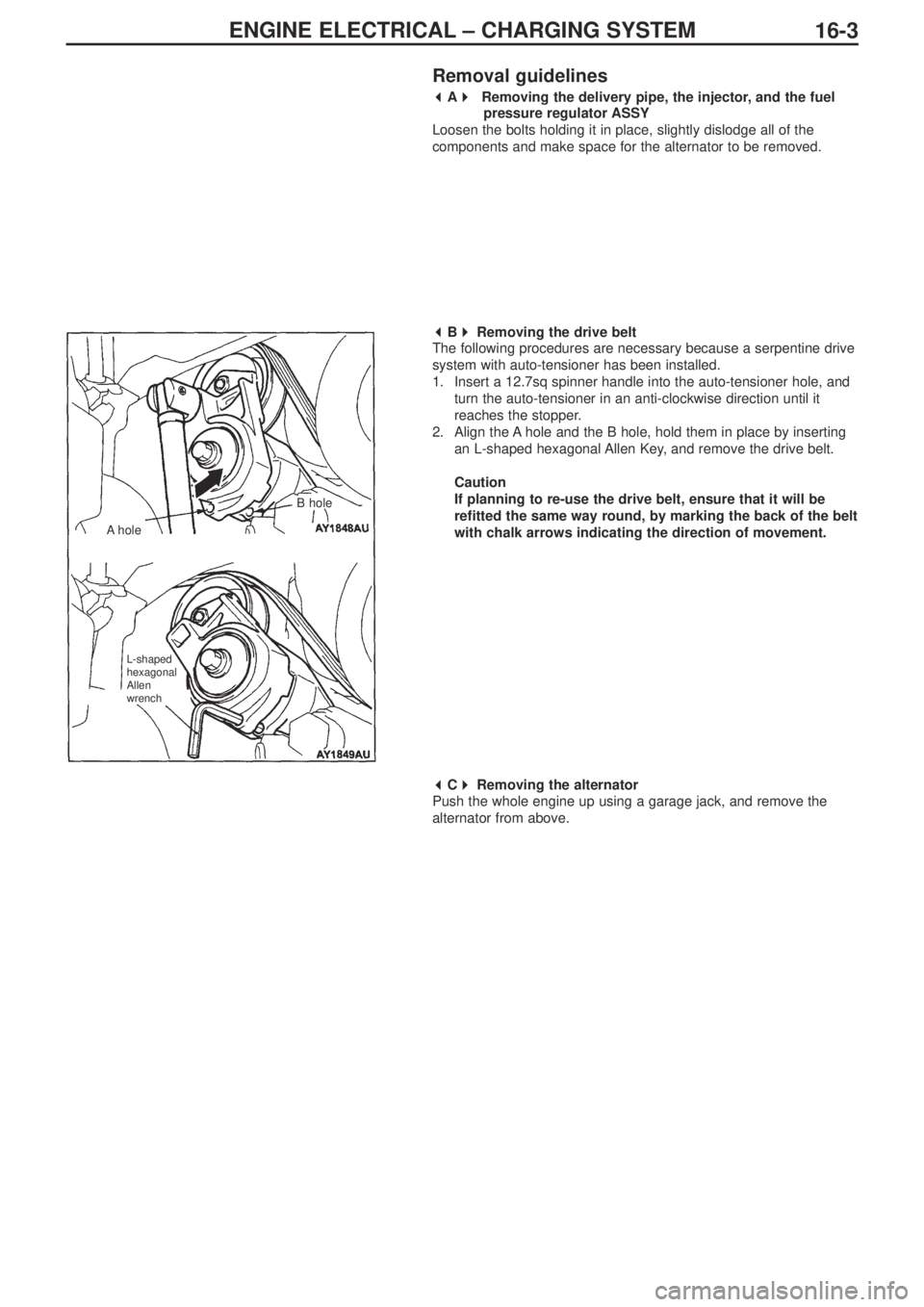
� �
B� �
Removing the drive belt
The following procedures are necessary because a serpentine drive
system with auto-tensioner has been installed.
1. Insert a 12.7sq spinner handle into the auto-tensioner hole, and
turn the auto-tensioner in an anti-clockwise direction until it
reaches the stopper.
2. Align the A hole and the B hole, hold them in place by inserting
an L-shaped hexagonal Allen Key, and remove the drive belt.
Caution
If planning to re-use the drive belt, ensure that it will be
refitted the same way round, by marking the back of the belt
with chalk arrows indicating the direction of movement.
� �
C� �
Removing the alternator
Push the whole engine up using a garage jack, and remove the
alternator from above.
AholeB hole
L-shaped
hexagonal
Allen
wrench